
Related Manuals for Mitsubishi Electric GUG-01SL-E


Summary of Contents for Mitsubishi Electric GUG-01SL-E
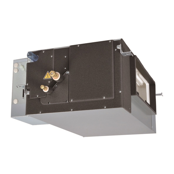
- Page 1 September. 2016 DIRECT EXPANSION COIL UNIT FOR LOSSNAY Model : GUG-01SL-E TECHNICAL MANUAL GUG-02SL-E GUG-03SL-E Lossnay Return Air and Supply Air Temperature Control Now Possible!
-
Page 2: Table Of Contents
CONTENTS CHAPTER 1 What Dx-coil unit is Basic function ..............................Two temperature control method ........................CHAPTER 2 System configurations System pattern outline ............................ Technical notes ..............................The conditions when Dx-coil unit is forcibly thermo-OFF .................. Water level sensor ............................Drain pump operation ............................CHAPTER 3 Specifications Operation range .............................. -
Page 4: Basic Function
What Dx-coil unit is CHAPTER 1. Basic function Dx-coil (Direct Expansion Coil) unit is a kind of temperature control equipment working with Lossnay unit and Mr.Slim outdoor unit to control Return Air temperature or Supply Air temperature. Dx-coil unit Lossnay unit Connection image This picture shows the system of LGH-100RVX-E and GUG-02SL-E as example. - Page 5 What Dx-coil unit is/ .Two temperature control method CHAPTER 2.3 Application examples Supplemental Air-conditioning System RA Temperature Control Supplemental air-conditioning systems Temperature setting range that combine the use of Dx-coil and Heating: 17-28°C / Cooling: 19-30°C / Auto: 19-28°C Lossnay units are now possible. Necessary fresh Medium air volume...
-
Page 6: System Pattern Outline
System configurations CHAPTER 1. System pattern outline The system of Lossnay unit and Dx-coil unit can be used as a few system patterns. • System pattern X: One remote controller • System pattern Y: Two remote controllers • System pattern Z: M-NET connection Depending on the pattern, the way to operate system, available functions, information can be monitored etc. - Page 7 System configurations/ . System pattern outline CHAPTER 1.4 Operation from each remote controller System pattern X System pattern Y System pattern Z ON/OFF From PZ-01RC From PZ-01RC or From one of the remote controllers or when PZ-61DR-E *1 the indoor unit is switched ON/OFF *2 Operation mode From PZ-01RC From PZ-01RC...
-
Page 8: Technical Notes
System configurations/ .Technical notes CHAPTER 1.5 External fan speed control without Lossnay remote controller When Lossnay remote controller (PZ-61DR-E) is not used in the system pattern X or Z, Lossnay fan speed can be controlled by external input like 0-10VDC (CN26) or volt-free contact (CN17). Refer to the installation manual and the technical manual of Lossnay unit for more detailed information such as how to set, how to select. - Page 9 System configurations/ .Technical notes CHAPTER Prohibition for multiple connection. Following configurations are bad examples. Do not construct systems same as below. Lossnay unit Outdoor unit Multiple Lossnay units Power supply connection is prohibited. Lossnay unit Dx-coil unit Power supply Power supply Outdoor unit Multiple outdoor units connection is prohibited.
- Page 10 System configurations / .Technical notes CHAPTER Prohibition for Lossnay remote controller. Following configurations are bad examples. Do not construct systems same as below. Lossnay unit Outdoor unit Dx-coil unit Power supply Power supply PZ-61DR-E PZ-61DR-E PZ-01RC PZ-01RC Two PZ-61DR-E Two PZ-01RC connection is prohibited.
- Page 11 System configurations / .Technical notes CHAPTER <CAUTION> When interlocking with Mr.Slim or external device through TM2 , there is a restriction to use “ON interlock mode” , “OFF interlock mode” and “External priority ON/OFF interlock mode” of Lossnay unit. DIP-SW PZ-61DR-E Interlock setting SW No.
-
Page 12: The Conditions When Dx-Coil Unit Is Forcibly Thermo-Off
System configurations / 3. The conditions when Dx-coil unit is forcibly thermo-OFF/4. Water level sensor/5. Drain pump operation CHAPTER 3. The conditions when Dx-coil unit is forcibly thermo-OFF Under the conditions listed below, Dx-coil unit is always and forcibly thermo-OFF. Dx-coil unit cannot be thermo-ON for about 10 minutes after the condition is canceled. -
Page 13: Operation Range
LGH-200RVXT-E Connectable outdoor unit PUHZ-ZRP50 PUHZ-ZRP50 PUHZ-ZRP71 PUHZ-ZRP71 PUHZ-ZRP71 Note: GUG-01SL-E cannot be used for the SA temperature control function. 3. Refrigerant pipe size information Dx-coil unit GUG-01SL-E GUG-02SL-E GUG-03SL-E Ref. pipe size of unit A / B 6.35 / 12.7 9.52 / 15.88... -
Page 14: Specifications
Specifications / 4. Specifications CHAPTER 4. Specifications GUG-01SL-E (connection to LGH-50RVX-E or LGH-65RVX-E) Refrigerant R410A Electrical power supply 220-240V / 50Hz, 220V / 60Hz (Supplied from outdoor unit) Input power Heating / Fan: 2.5W, Cooling: 12.4W Running current Less than 0.1A... - Page 15 Specifications / 4. Specifications CHAPTER GUG-03SL-E (Connection to LGH-150RVX-E or LGH-200RVX-E) Refrigerant R410A Electrical power supply 220-240V / 50Hz, 220V / 60Hz (Supplied from outdoor unit) Input power Heating / Fan: 2.5W, Cooling: 12.4W Running current Less than 0.1A Weight 28kg *Accessories: Approx.
-
Page 16: Characteristic Curve
Following figures show air volume drop when connecting Dx-coil unit. The air flow range is limited because of the protection for overload of outdoor unit when Dx-coil unit is connected. LGH-50RVX-E LGH-65RVX-E Without GUG-01SL-E With GUG-01SL-E Without GUG-01SL-E With GUG-01SL-E... - Page 17 Specifications / 5. Characteristic curve CHAPTER LGH-80RVX-E LGH-100RVX-E LGH-100RVX-E Without GUG-02SL-E With GUG-02SL-E Without GUG-02SL-E With GUG-02SL-E 1000 1500 1000 1200 (L/s) (L/s) Air volume Air volume LGH-200RVX-E LGH-150RVX-E Without GUG-03SL-E With GUG-03SL-E Without GUG-03SL-E With GUG-03SL-E 1000 1500 2000 2500 3000 1000...
- Page 18 Specifications / 5. Characteristic curve CHAPTER LGH-250RVXT-E SA temperature control RA temperature control Without GUG-03SL-E With GUG-03SL-E Without GUG-03SL-E With GUG-03SL-E 1000 2000 3000 4000 1000 2000 3000 4000 900 1000 1100 (L/s) 900 1000 1100 (L/s) Air volume Air volume [Reference information] Recovery of static pressure losing by Dx-coil unit.
-
Page 19: Outlines And Dimensions
(Only for GUG-02 and 03SL-E) Drain pump Heat exchanger Note: The drain pump always runs in the cooling mode and continues to run for six minutes after the unit stops. GUG-01SL-E Heat exchanger Ceiling suspension fixture (4-13 X 20 oval) Air inlet from... - Page 20 Outlines and Dimensions / 1. Outlines and dimensions CHAPTER GUG-02SL-E Heat exchanger Ceiling suspension fixture (4-13 X 20 oval) Air inlet from Lossnay (supply air) Control box Inspection opening An inspection opening is required for 450 x 450 or Drain pump more installation and regular maintenance (check) of the drain pump.
-
Page 21: Installation Example
Outlines and Dimensions/ 2. Installation example CHAPTER 2. Installation example 2.1 GUG-01SL-E and GUG-02SL-E Top view (to install straight duct) Duct (Field supply) Note: •The distance between the Lossnay unit and the Dx-coil unit must be between 25 cm and 5 m when the duct is straight. - Page 22 Outlines and Dimensions/ 2. Installation example CHAPTER 2.2 GUG-03SL-E with LGH-150/200RVX-E Following duct works is example using chamber box between LGH-150/200RVX-E and GUG-03SL-E. Top view (with chamber box) Chamber box (field supply) Rectangular duct (field supply) Duct (field supply) Note: •The distance between the Lossnay unit and the Dx-coil unit must be between 25 cm and 5 m when the duct is straight.
-
Page 23: Wiring Diagram
Wiring Diagram CHAPTER 1. Wiring diagram Note: 1. TB6, TM104 and CN120 shown in dotted lines are field work. 2. Make sure to connect the ground wire. 3. Prior to access the electrical parts cut off the power supply (all to Dx-coil unit, Lossnay unit and outdoor unit) more than five minutes. -
Page 24: Connecting The Power Supply Cable
Wiring Diagram / 2. Connecting the power supply cable / 3. Connecting PZ-01RC / 4. Connecting Lossnay unit CHAPTER 2. Connecting the power supply cable Insert the cutting Bush Pass the power supply cable through the bush* and connect to the TB6 terminal PG connector Screw for earth lead block using the round terminals. -
Page 25: Function Setting
The system of the Lossnay unit and Dx-coil unit is designed to maintain the supply air temperature close to the setting temperature. GUG-01SL-E cannot be used for SA temperature control. The setting temperature is recommended to be the same as or close to the setting temperature of the air conditioning unit. - Page 26 Other Functions / 1. Function setting CHAPTER No. 3 Fixed set temperature Set the SW2-3, SW2-4 and SW2-5 as below. SW2-3 SW2-4 SW2-5 Setting check Contents Not fixed (Remote controller setting) (Factory setting) Cooling, Auto 19 ˚C fixed Heating 17 ˚C fixed 20 ˚C fixed 22 ˚C fixed PCB A of Dx-coil unit...
- Page 27 SW 11-9 and 11-10 on PCB B is to identify the model for PCB. When replacing to a new PCB, use the same setting as old one or an indicated below. SW11-9 SW11-10 Setting check Contents New PCB for replacement GUG-01SL-E PCB B of Dx-coil unit GUG-02SL-E GUG-03SL-E *Do not change from factory setting. If changed, please set as the factory setting.
- Page 28 Other Functions / 1. Function setting CHAPTER No. 9 Setting whether or not the Dx-coil unit is connected Set the SW7-1 as below. DIP-SW PZ-61DR-E Setting check Setting check Contents SW No. Setting Function No. Setting data DIP-SW priority (Factory setting) SW7-1 When the Dx-coil unit is NOT (PCB of...
- Page 29 Other Functions / 1. Function setting CHAPTER Selection of the operation mode from “Temp. priority mode” , “Fan No. 10 speed priority mode” or“ Fan priority mode after temp. priority mode” . This function is only available for the Lossnay unit produced after September 2016, whose serial No. should be after 16090001. Or its software version indicated in Lossnay PCB should be more than 06.
-
Page 30: Dip Switch Setting
Other Functions / 2. Dip switch setting 3. Lossnay functions CHAPTER Usage example Following example shows using Fan priority mode after temp. priority mode for 2 hours; in the case of setting SW7-2 and SW7-3 both are ON. Units are OFF for more than 2 hours. Settable from 1 to 4 hours with the step of 30 minutes increments. -
Page 31: Remote Controller Pz-01Rc
Remote Controller PZ-01RC CHAPTER 1. Remote controller PZ-01RC As an accessory, a remote controller is packaged in a carton box being delivered with Dx-coil unit. The dedicated remote controller for Dx-coil unit is described as “PZ-01RC” in this manual. However it is not an official model name so that it is not possible to buy separately. -
Page 32: Appearance
Remote Controller PZ-01RC / 3. Appearance CHAPTER 3. Appearance Display The main display can be displayed in two different modes: “Full” and “Basic” . The factory setting is “Full” . Operation mode Full mode Appears when the buttons are locked. Dx-coil unit operation mode appears here. -
Page 33: Outlines And Dimensions
Remote Controller PZ-01RC / 4. Outlines and dimensions CHAPTER 4. Outlines and dimensions 19 [3/4] 46 [1-13/16] 120 [4-23/32] (Front view) (Side view) (Rear view) <Specifications> Product size 120(W) × 120(H) × 19(D)mm (4 3/4 × 4 3/4 × 3/4 [ in ]) ( not including the protruding part ) Net weight 0.25kg (9/16lb.) -
Page 34: Initial Setting
Remote Controller PZ-01RC / 5. Initial setting CHAPTER 5. Initial setting Before starting to operate of the system, the following setting are required. (1) For the SA temp. control, set the Room temperature not to be displayed using the following steps. Note: For the RA temp. - Page 35 Remote Controller PZ-01RC / 5. Initial setting CHAPTER (3)Initial settings from the menu Press “MENU” button from the Main display and select “Initial setting” . The following selections will be listed. Main/Sub • Clock • Main display • Contrast • Display details •...
-
Page 36: Basic Operations
Remote Controller PZ-01RC / 6. Basic operations 7. Troubleshooting CHAPTER 6. Basic operations Operation mode icons Heat Cool Auto Auto cool Auto heat Turning ON and selecting operation mode Press button ( ON/OFF ). Press button ( F1 ) to go through the The ON/OFF lamp and will light up. -
Page 37: Timer And Weekly Timer
Remote Controller PZ-01RC / 8. Timer and Weekly timer 9. Service 10. Others CHAPTER 8. Timer and Weekly timer The settings for Timer and Weekly timer operation can be made from the remote controller. Main Main menu Vane·Louver·Vent. (Lossnay) Press button ( MENU ) to go to the Main menu, and move the cursor to the desired setting High power Timer... -
Page 38: Refrigerant System Diagram
Refrigerant system diagram CHAPTER 1. Refrigerant system diagram Strainer(#50) Heat exchanger Refrigerant GAS pipe connection (Flare) Thermistor TH5 (Cond/Eva.temperature) Refrigerant flow in cooling Refrigerant flow in heating Refrigerant LIQUID pipe connection (Flare) Distrbutor Thermistor TH2 with strainer(#50) Pipe temperature(Liquid) Strainer(#50) Thermistor TH11 (Inlet air temperature) Themmistor TH9... -
Page 39: Chapter 9 Model Selection And Capacity Calculation
Model selection and capacity calculation CHAPTER In this chapter, the calculation ways to select Lossnay unit, Dx-coil unit and outdoor unit are explained. Follow each steps shown in the flow chart below to select adequate units. The model selection and the capacity calculation are partly available on “New Design-Tool(version 1.70)” . Flow chart for model selection Start STEP1... - Page 40 Model selection and capacity calculation CHAPTER Definition of each air flow name used in following calculation Return air Lossnay unit Outdoor air Exhaust air Dx-coil unit Outdoor unit Refrigerant pipe Lossnay outlet air = Dx-coil inlet air Supply air Definition of the text box Example values are filled in this normal box for each situation.
- Page 41 Model selection and capacity calculation CHAPTER II : Calculation of cooling load to determine the required capacity Cooling Load Classifications Class Heat Load Heat generated from walls (qws) from direct sunlight Heat generated from glass Indoor penetration heat from conduction and convection Accumulated heat load in walls (qss) Sensible heat (q...
- Page 42 PUHZ-ZRP50 PUHZ-ZRP71 PUHZ-ZRP71 PUHZ-ZRP71 outdoor unit Note: GUG-01SL-E cannot be used for the SA temperature control function. Refer to page 10 for pipe size information. Lossnay model Adequate Dx-coil unit model GUG-02SL-E LGH-100RVX-E Temperature control feature Adequate outdoor unit model...
- Page 43 Model selection and capacity calculation CHAPTER STEP3-1. Calculation of Dx-coil unit cooling capacity Calculation steps Read out characteristics from the specification sheet Calculate Dx-coil inlet air (Lossnay outlet air) condition Calculate the capacity of Dx-coil unit Calculate supply air conditions from Dx-coil unit I : Read out characteristics from the specification sheet (1) Calculation conditions (A) Lossnay + Dx-coil System configuration...
- Page 44 Model selection and capacity calculation CHAPTER (2) Air condition difference factor Characteristics written in the specification sheet are based on air conditions of outdoor air: 35˚CDB, 24˚CWB and return air: 27˚CDB, 19˚CWB. Read out the air volume factor C by outdoor air dry-bulb temperature and Dx-coil inlet air wet-bulb temperature using the performance curves on the page 62.
- Page 45 Model selection and capacity calculation CHAPTER Calculate supply air temperature using SHF (sensible heat factor) given in the table below. SHF at the air condition of Outdoor air 33˚CDB, 63%RH (27˚CWB) and Return air 26˚CDB, 50%RH (18.7˚CWB). [SA temperature control] SHF is calculated by following formula.
- Page 46 Model selection and capacity calculation CHAPTER STEP4. Comparison of Lossnay + Dx-coil unit capacity with required capacity By calculations from STEP 1 to 3, the capacity of Lossnay + Dx-coil unit is summate as shown below. Capacity calculation result (A) Required cooling capacity 31.4 kW (B) Lossnay energy recovery 7.5 kW...
- Page 47 Model selection and capacity calculation CHAPTER III : Calculation of Lossnay energy recovery effect (A) Lossnay model LGH-100RVX-E (B) Temperature exchange efficiency for winter (at 1000m 80 % (C) Enthalpy exchange efficiency on heating (at 1000m 72.5 % (D) Lossnay outlet air temperature 16 ˚C = ( (I) –...
- Page 48 Model selection and capacity calculation CHAPTER STEP3-2. Calculation of Dx-coil unit heating capacity Calculation steps Read out characteristics from the specification sheet Calculate Dx-coil inlet air (Lossnay outlet air) condition Calculate the capacity of Dx-coil unit Calculate supply air conditions from Dx-coil unit I : Read out characteristics from the specification sheet (1) Calculation conditions (A) Lossnay + Dx-coil System configuration...
- Page 49 Model selection and capacity calculation CHAPTER Specification condition (A) Outdoor air wet-bulb temperature ˚C (B) Dx-coil inlet air dry-bulb temperature 17.4˚CDB (C) Air condition difference factor C 1.02 All of cooling specification for each Dx-coil unit are designed under above condition. Therefore C ( = 1.02) is fixed value for all unit.
- Page 50 Model selection and capacity calculation CHAPTER Example 2-1: Cooling for an school classroom by RA temperature control Following calculations are just examples. In the actual designing, please calculate in an appropriate way. STEP1 . Calculation of required cooling capacity I : Calculation of required ventilation air volume and selection of Lossnay unit (A) Floor space 50 m (B) Required fresh air rates...
- Page 51 Model selection and capacity calculation CHAPTER III: Calculation of Lossnay energy recovery effect (A) Lossnay model LGH-100RVX-E (B) Temperature exchange efficiency for summer (at 1000m 72 % (C) Enthalpy exchange efficiency on cooling (at 1000m 71 % (D) Lossnay outlet air temperature 22.7 °C = (G) –...
- Page 52 Calculate supply air temperature usig SHF(sensible heat factor) given in the table below. SHF at the air condition of Outdoor air 27°CDB, 50%RH (19.5°CWB) and Return air 21°CDB, 53%RH (15°CWB). [RA temperature control] Dx-coil unit GUG-01SL-E GUG-02SL-E GUG-03SL-E LGH- LGH-...
-
Page 53: Dry-Bulb Temperature [˚C]
Model selection and capacity calculation CHAPTER Supply air condition from Dx-coil can be read out by psychrometric chart. Supply Air from Dx-coil unit Dry-bulb temperature [°C] 10.5 Wet-bulb temperature [°C] Absolute humidity [kg/kg(DA)] 0.0066 Relative humidity Enthalpy [kJ/kg(DA)] 27.2 Because of supply air temperature is lower than dew point temperature of indoor air(11°C), there is a possibility of water condensation occurring around the outlet duct. -
Page 54: Enthalpy [Kj/Kg(Da)]
Model selection and capacity calculation CHAPTER Example 2-2 : Heating for a school classroom by RA temperature control STEP1. Calculation of required heating capacity I : Calculation of required ventilation air volume and selection of Lossnay unit In this Example 2-2, the floor is assumed same room with Example 2-1. Required air volume is same with Example 2-1. -
Page 55: Wet-Bulb Temperature [˚C
Model selection and capacity calculation CHAPTER II : Calculate Dx-coil inlet air (Lossnay outlet air) condition See the calculations and table in STEP1-III. III : Calculate the capacity of Dx-coil unit (1) Air volume factor (A) Designing air volume 1000 m 1000 m (B) Related air volume of Lossnay unit at fan speed 4 (C) Air volume ratio = (A) / (B) -
Page 56: Enthalpy [Kj/Kg(Da)]
Model selection and capacity calculation CHAPTER Example 3-1 : Cooling for an office floor by SA temperature control For details of each calculation, see Example 1-1. STEP1. Calculation of required cooling capacity I: Calculation of required ventilation air volume and selection of Lossnay unit The floor is assumed same room with Example 1-1. - Page 57 Model selection and capacity calculation CHAPTER II : Calculate the capacity of Dx-coil unit (1) Air volume factor (A) Air volume factor C (2) Air condition difference factor (A) Total air condition difference factor C 1.04 For the quick reference of air condition difference factor C , see the page 63.
- Page 58 Model selection and capacity calculation CHAPTER Example 3-2 : Heating office floor by SA temperature control For details of each calculation, see Example 1-2. STEP1. Calculation of required heating capacity I : Calculation of required ventilation air volume and selection of Lossnay unit The floor is assumed same room with Example 1-1.
- Page 59 Model selection and capacity calculation CHAPTER II : Calculate the capacity of Dx-coil unit (1) Air volume factor (A) Air volume factor C (2) Air condition difference factor (A) Total air condition difference factor C 0.71 For the quick reference of air condition difference factor C , see the page 63.
- Page 60 Model selection and capacity calculation CHAPTER STEP3-3. Selection of DX-coil unit by supply air temperature In this step3-3, the outline graph of the average supply air temperature during SA temperature control operation is shown. Following graph is just an example based on some theoretical conditions. It might be different from the actual operation.
- Page 61 Model selection and capacity calculation CHAPTER I : Cooling LGH-80RVX-E + GUG-02SL-E + PUHZ-ZRP50 Return air condition: 21˚CDB, 50%RH Return air condition: 24˚CDB, 50%RH Lossnay outlet air temperature Lossnay outlet air temperature Supply air temperature from Dx-coil unit can range Supply air temperature from Dx-coil unit can range this area with ±3˚C accuracy.
- Page 62 Model selection and capacity calculation CHAPTER LGH-200RVX-E or LGH-200RVXT-E + GUG-03SL-E + PUHZ-ZRP71 Return air condition: 21˚CDB, 50%RH Return air condition: 24˚CDB, 50%RH Lossnay outlet air temperature Lossnay outlet air temperature Supply air temperature from Dx-coil unit can range Supply air temperature from Dx-coil unit can range this area with ±3˚C accuracy.
- Page 63 Model selection and capacity calculation CHAPTER II : Heating LGH-80RVX-E + GUG-02SL-E + PUHZ-ZRP50 Return air condition: 21˚CDB, 50%RH Return air condition: 24˚CDB, 50%RH Supply air temperature from Dx-coil unit can range Supply air temperature from Dx-coil unit can range this area with ±3˚C accuracy.
- Page 64 Model selection and capacity calculation CHAPTER LGH-200RVX-E or LGH-200RVXT-E + GUG-03SL-E + PUHZ-ZRP71 Return air condition: 21˚CDB, 50%RH Return air condition: 24˚CDB, 50%RH Supply air temperature from Dx-coil unit can range Supply air temperature from Dx-coil unit can range this area with ±3˚C accuracy. this area with ±3˚C accuracy.
-
Page 65: Air Volume Factor
Performance Data CHAPTER 1. Air volume factor Cooling Heating Air Volume ratio (= actual air volume / related air volume at fan speed 4) 2. Performance curves Cooling capacity Dx-coil inlet air (Lossnay outlet air) wet-bulb temperature <W.B. °C> Outdoor air dry-bulb temperature <D.B.°C > Heating capacity Dx-coil inlet air (Lossnay outlet air) dry-bulb temperature <D.B. -
Page 66: Capacity Ratio Against Corrected Refrigerant Pipe Length
Return air conditions are assumed that is stable at 21°CDB, 50%RH or 24°CDB, 50%RH. And outdoor air relative humidity is also assumed that is stable. (1) Cooling Outdoor air dry-bulb temperature [°CDB] / 50%RH Return air 21°CDB, 50%RH LGH-50RVX-E + GUG-01SL-E 0.90 0.91 0.92 0.92 0.93... - Page 67 Performance Data/ . Quick reference for the air condition difference factor C CHAPTER Outdoor air dry-bulb temperature [°CDB] / 50%RH Return air 27°CDB, 50%RH LGH-50RVX-E + GUG-01SL-E 1.02 1.02 1.03 1.03 1.04 1.04 1.05 1.06 1.06 1.07 1.07 LGH-65RVX-E + GUG-01SL-E 1.02...
-
Page 68: Cooling Capacity And Shf (Sensible Heat Factor) Table Against Return And Outdoor Air Temperature
(kW) LGH-50RVX-E 3.30 2.06 0.63 3.33 2.01 0.60 3.33 1.92 0.58 3.33 1.97 0.59 3.50 1.93 0.55 3.40 1.74 0.51 GUG-01SL-E 3.40 1.85 0.54 3.47 1.83 0.53 3.50 1.77 0.50 3.47 1.80 0.52 3.60 1.76 0.49 3.40 1.55 0.46 PUHZ-ZRP35 3.30... - Page 69 Performance Data/ 5. Cooling capacity and SHF (sensible heat factor) table against return and outdoor air temperature. CHAPTER Outdoor air temperature [DB(°C)] Return air System (℃) (℃) (kW) (kW) (kW) (kW) (kW) (kW) (kW) (kW) (kW) (kW) (kW) (kW) LGH-80RVX-E 4.58 2.89 0.63...
- Page 70 Performance Data/ 5. Cooling capacity and SHF (sensible heat factor) table against return and outdoor air temperature. CHAPTER Outdoor air temperature [DB(°C)] Return air System (℃) (℃) (kW) (kW) (kW) (kW) (kW) (kW) (kW) (kW) (kW) (kW) (kW) (kW) LGH-150RVX-E 8.71 5.42 0.62...
- Page 71 Performance Data/ 5. Cooling capacity and SHF (sensible heat factor) table against return and outdoor air temperature. CHAPTER Outdoor air temperature [DB(°C)] Return air System (℃) (℃) (kW) (kW) (kW) (kW) (kW) (kW) (kW) (kW) (kW) (kW) (kW) (kW) LGH-150RVXT-E 8.71 5.43 0.62...
- Page 72 Performance Data/ 5. Cooling capacity and SHF (sensible heat factor) table against return and outdoor air temperature. CHAPTER Outdoor air temperature [DB(°C)] Return air System (℃) (℃) (kW) (kW) (kW) (kW) (kW) (kW) (kW) (kW) (kW) (kW) (kW) (kW) LGH-250RVXT-E 11.46 8.26 0.72...
- Page 73 Performance Data/ 5. Cooling capacity and SHF (sensible heat factor) table against return and outdoor air temperature. CHAPTER Outdoor air temperature [DB(°C)] Return air System (℃) (℃) (kW) (kW) (kW) (kW) (kW) (kW) (kW) (kW) (kW) (kW) (kW) (kW) LGH-100RVX-E 4.86 3.14 0.65...
- Page 74 Performance Data/ 5. Cooling capacity and SHF (sensible heat factor) table against return and outdoor air temperature. CHAPTER Outdoor air temperature [DB(°C)] Return air System (℃) (℃) (kW) (kW) (kW) (kW) (kW) (kW) (kW) (kW) (kW) (kW) (kW) (kW) LGH-200RVX-E 6.78 4.94 0.73...
- Page 75 Performance Data/ 5. Cooling capacity and SHF (sensible heat factor) table against return and outdoor air temperature. CHAPTER Outdoor air temperature [DB(°C)] Return air System (℃) (℃) (kW) (kW) (kW) (kW) (kW) (kW) (kW) (kW) (kW) (kW) (kW) (kW) LGH-200RVXT-E 6.78 4.97 0.73...
- Page 76 Y16-005 Sep.2016 <MEE>...
Need help?
Do you have a question about the GUG-01SL-E and is the answer not in the manual?
Questions and answers