Table of Contents
Advertisement
Instruction Manual
D104239X012
Service Manual for Multiport Flow
Selector
Valve
™
Contents
. . . . . . . . . . . . . . . . . . . . . . . . . . . . . . . . .
. . . . . . . . . . . . . . . . . . . . . . . . . . . . . . . .
. . . . . . . . . . . . . . . . . . . . . . . . . . . . . . . . . .
. . . . . . . . . . . . . . . . . . . . . . . . . . . . . . . . .
. . . . . . . . . . . . . . . . . . . . . . . . . . . . . . . . .
. . . . . . . . . . . . . . . . . . . . . . . . . . . . . . . . . . . .
. . . . . . . . . . . . . . . . . . . . . . . . . . . . . . . . . . . . . .
. . . . . . . . . . . . . . . . . . . . . . . . . . . . . . . . . . . . . . .
. . . . . . . . . . . . . . . . . . . . . . . . . . . . . . . . . . . . .
. . . . . . . . . . . . . . . . . . . . . . . .
. . . . . . . . . . . . . . . . . . . . . . . . . . . . .
. . . . . . . . . . . . . . . . . . . . . . . . . . .
. . . . . . . . . . . . . . . . . . . . . . . . . . . . . . . . . . .
Introduction
Scope of Manual
This instruction manual includes installation, operation, and maintenance information for the Multiport Flow Selector.
Do not install, operate, or maintain a Multiport Flow Selector without being fully trained and qualified in valve,
actuator, and accessory installation, operation, and maintenance. To avoid personal injury or property damage, it is
important to carefully read, understand, and follow all the contents of this manual, including all safety cautions and
warnings. If you have any questions about these instructions, contact your
www.Fisher.com
. . . . . . .
. . . . .
. . . . . . . . . . . . . . . . . . . .
. . . . . . . . . . . . . . . . . . . .
. . . . . . . . . . . . . .
. . . . . . . . . . . . . . . . . . . .
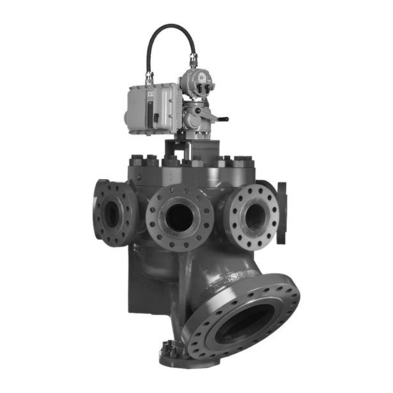
Figure 1. Fisher Multiport Flow Selector Valve
1
3
4
5
5
6
6
7
7
8
8
8
9
10
11
12
15
18
19
X1398
Emerson sales office
Multiport Flow Selector
January 2019
before proceeding.
Advertisement
Chapters
Table of Contents

Subscribe to Our Youtube Channel
Related Manuals for Emerson Fisher Multiport Flow Selector


Summary of Contents for Emerson Fisher Multiport Flow Selector
-
Page 1: Table Of Contents
™ Contents Figure 1. Fisher Multiport Flow Selector Valve Introduction ....... . . - Page 2 Educational Services For information on available courses for the Multiport Flow Selector valve, as well as a variety of other products, contact: Emerson Automation Solutions Educational Services - Registration Phone: 1-641-754-3771 or 1-800-338-8158 E-mail: education@emerson.com emerson.com/fishervalvetraining...
-
Page 3: Specifications
Instruction Manual Multiport Flow Selector D104239X012 January 2019 Specifications The Multiport Flow Selector specifications are given in tables 1 through 5. Table 1. Valve Specifications NPS 2x4 and 3x6 VALVE SIZE SPECIFICATIONS 2 x 4 3 x 6 ASME Class Rating CL300 CL600 CL900... -
Page 4: Installation
Instruction Manual Multiport Flow Selector January 2019 D104239X012 Installation Minimum Tools Required A torque wrench, socket wrench, and Allen head wrenches are required to install the Multiport Flow Selector Valve and actuator assembly. Table 4. Socket Size for Multiport Bonnet Studs and Nuts VALVE SIZE, NPS ASME CLASS RATING SOCKET SIZE (in) -
Page 5: Field Technician Commissioning Activities
Instruction Manual Multiport Flow Selector D104239X012 January 2019 Key numbers in this procedure are shown in figure 2 and 3 unless otherwise indicated. Before installing the unit, observe all warning tags and: 1. Check for external physical damage. 2. Check for any visible leakage of gear oil from the Multiport Electric Actuator (MPA). 3. -
Page 6: Home Port Calibration
Instruction Manual Multiport Flow Selector January 2019 D104239X012 down by tightening the nuts. Proper assembly has occurred if there are flat washers between the travel indicator spacers and travel indicator plate and travel indicator plate and nuts. Regardless of size, an anti-seize lubricant (key 40) shall be applied to the threaded portion of the fasteners and nuts 4. -
Page 7: Maintenance
Instruction Manual Multiport Flow Selector D104239X012 January 2019 Maintenance Refer to figure 2 and 3, typical Multiport assembly and mounting drawings. WARNING Avoid personal injury from sudden release of process pressure. Before performing any maintenance operations: D Do not remove the actuator from the valve while the valve is still pressurized. D Disconnect any operating lines providing air pressure, electric power, or a control signal to the actuator. -
Page 8: Assembly
Instruction Manual Multiport Flow Selector January 2019 D104239X012 Note The bonnet can be removed with the Multiport Electric Actuator still attached. If this is done, ensure proper orientation has been maintained between the actuator and valve body once the bonnet has been re-installed onto the valve body. If this orientation has not been maintained, recalibration of the actuator is required. -
Page 9: Bonnet
Instruction Manual Multiport Flow Selector D104239X012 January 2019 3. Install the back up plate (key 16) against the shoulder in the plug (key 2). 4. Install the O-ring (key 14) onto the seal carrier (key 13). Install the seal assembly into the plug. Hand force should only be required for proper installation. -
Page 10: Plug Seal Adjustment
Instruction Manual Multiport Flow Selector January 2019 D104239X012 Table 6. Bonnet Bolting Torque STUD SIZE TORQUE VALVE SIZE, ASME CLASS RATING Inch N•m ft•lbf 2 x 4 25.4 31.8 1-1/4 3 x 6 1500 38.1 1-1/2 4 x 8 34.9 1-3/8 4 x 10 1500... -
Page 11: Troubleshooting
The sealing surface of the seal insert should be smooth, completely intact, and free of deep groove marks. WARNING Ensure that all pressures in the Multiport body, group outlet, and test port are ZERO before visually checking the seal. 3. If more information is required, please contact your Emerson sales office. -
Page 12: Drawing Assembly
Instruction Manual Multiport Flow Selector January 2019 D104239X012 Figure 2. Multiport Drawing Assembly VIEW C VIEW B VIEW B VIEW D SCALE 2:1 VIEW A VIEW D VIEW E SCALE 2:1 VIEW E SCALE 3:1 VIEW A SCALE 2:1 VIEW C GE99805 SCALE 2:1 APPLY LUB/SEALANT... -
Page 13: D104239X012 January
Instruction Manual Multiport Flow Selector D104239X012 January 2019 Figure 3. Multiport Mounting Assembly for NPS 3x6, 4x8, and 6x16 Constructions GE99891... - Page 14 Instruction Manual Multiport Flow Selector January 2019 D104239X012 Parts Kits Recommend Seal Kits PART NUMBER MAJOR REPAIR KIT, AFLAS FOR 2x4 MPFS RVAE0-960-952 MAJOR REPAIR KIT, AFLAS FOR 3x6 MPFS RVAE0-960-953 MAJOR REPAIR KIT, AFLAS FOR 4x8 MPFS RVAE0-960-954 MAJOR REPAIR KIT, AFLAS/FLEXISEAL FOR 2x4 MPFS RVAE0-960-957 MAJOR REPAIR KIT, AFLAS/KALREZ FOR 3x6 MPFS RVAE0-960-959...
-
Page 15: Parts List
Parts List WARNING Use only genuine Fisher replacement parts. Components that are not supplied by Emerson Automation Solutions should not, under any circumstances, be used in any Fisher valve, because they may void your warranty, might adversely affect the performance of the valve, and could cause personal injury and property damage. - Page 16 Instruction Manual Multiport Flow Selector January 2019 D104239X012 Figure 4. Typical Multiport Seal Components PLUG SEAL SEAL BEARING WAVE SPRINGS ADJUSTMENT NUT BACKUP ASSEMBLY O-RING SEAT SEAL PLATE RING INSERT X1583 HIGH DIFFERENTIAL SEAL ASSEMBLY SCRAPER SCRAPER WAVE HIGH SPRING DIFFERENTIAL SEAL X1581 PLUG SEAL COMPONENTS...
- Page 17 Instruction Manual Multiport Flow Selector D104239X012 January 2019 Figure 5. Typical Multiport Seal Components SEAL ADJUSTMENT TOOL PLUG E-60681009 NOTE: PLUG (INDEX MARK CAN BE FOUND ON THE STEM FLAT THAT FACES THE SAME WAY AS THE PLUG SEAL OPENING.) PLUG SEAL ADJUSTMENT TOOL IN PLUG.
-
Page 18: Maintenance Checklist Procedure
Instruction Manual Multiport Flow Selector January 2019 D104239X012 Recommended Periodic Multiport Maintenance Checklist Procedure Half Yearly Check 1. Check the plug port position in LDM and the mechanical indicator respectively and in remote feedback 2. Check the plug travel sequence for smooth operation with local/remote 3. -
Page 19: Multiport Electric Actuator
Instruction Manual Multiport Flow Selector D104239X012 January 2019 Multiport Actuator O&M Manual — Supplied by Bettis Document No. MPS-400-0711 WARNING Use caution when working on, with, or around valves and actuators. High pressures, forces, voltages, and flammable media can be present. Read this manual in its entirety before installing, operating, or performing maintenance on the MPA valve actuator. - Page 20 Instruction Manual Multiport Flow Selector January 2019 D104239X012 Table of Contents Introduction ....... . Figure 1 –...
-
Page 21: Introduction
Instruction Manual Multiport Flow Selector D104239X012 January 2019 Introduction The Multi-Port Actuator is a Bettis single turn actuator for control of multi-port flow selectors (MPFS) with 3 to 8 ports. A typical application is oil or gas well selection for well production testing as shown in figure 1. Typically the MPA is the actuator of a Multi-Port Flow Selector as shown in figure 2. - Page 22 Instruction Manual Multiport Flow Selector January 2019 D104239X012 Figure 2. MPA Mounted on 6”x16” MPFS...
-
Page 23: Features
Instruction Manual Multiport Flow Selector D104239X012 January 2019 Features The actuator features several assemblies as shown in figure 3. Unique features of the actuator are listed below. LOCAL DISPLAY MODULE Figure 3. MPA Features (LDM) WITH DISPLAYS & STATUS LEDS. SELECTOR &... -
Page 24: Torque
Instruction Manual Multiport Flow Selector January 2019 D104239X012 5. High performance microcontroller updates motor control output every 4mS for precision motor control 6. 12-bit magnetic encoder coupled directly to torque pinion for torque feedback a. Provides torque measurement resolution of 0.146% of full torque 7. -
Page 25: Torque
Instruction Manual Multiport Flow Selector D104239X012 January 2019 b. Port position within 2° of port c. Motor running d. Alarm e. Over torque f. Position within 0.25° of home port 〉 g. Local mode 〉 Combined detection logic for two selector switches h. -
Page 26: Mechanical And Electrical Installation
Instruction Manual Multiport Flow Selector January 2019 D104239X012 11. Remote display module (RDM) option available a. RDM displays identical information and performs identical control as LDM b. Bettis's patented combined switch logic allows detection of selector switch position on LDM and RDM c. -
Page 27: Wiring
Instruction Manual Multiport Flow Selector D104239X012 January 2019 Wiring All user wiring terminations are made inside the Electrical Enclosure shown in figure 3. Refer to wiring diagram located at the back of this manual for wiring connections. High voltage power connections are made to the disconnect/circuit breaker located inside the electrical enclosure. -
Page 28: Local Display Module
Instruction Manual Multiport Flow Selector January 2019 D104239X012 Local Display Module Contains microprocessor controller, position encoder, and network interface. This is the main controller used to setup and operate the actuator. This module displays operating parameters, port position, torque, and alarms. It also provides a means to configure the actuator by using the local controls. -
Page 29: Local Operation
Instruction Manual Multiport Flow Selector D104239X012 January 2019 LOCAL – hands on operation at the actuator by manipulation of Control Knob. REMOTE – used within the context of plant operation, i.e. Remote Control Panel, PLC, DCS, etc. See wiring diagram for typical user wiring for remote control. -
Page 30: Display Blanking
Instruction Manual Multiport Flow Selector January 2019 D104239X012 PORT LED flashes Green when the actuator is within 2° and outside 1° prior to the setpoint of the selected port. The port LED flashes Red when within 2° and outside 1° beyond the setpoint. The port LED illuminates steady Green while within 1°... -
Page 31: Field Setup Using Dcmlink Software
Instruction Manual Multiport Flow Selector D104239X012 January 2019 Field Setup Using DCMLink Software DCMLink is an application for configuration, calibration, test, and operation of the MPA DCMLink is a licensed product. It is a Windows-based program. Compatible Windows Operating Systems are listed in the DCMLink IOM, DCM-402-0317. - Page 32 Instruction Manual Multiport Flow Selector January 2019 D104239X012 Communications Setup If connected to the RDM port, set the computer Baud Figure 9. Rate to 9600, Parity None and Stop Bits to 1. Set the Slave Address to 99. The RDM port configuration of the MPA is fixed at 9600,N,8,1 and may not be changed by the user.
-
Page 33: User Setups Menu
Instruction Manual Multiport Flow Selector D104239X012 January 2019 User Setup Menus o configure the actuator, select (highlight) the Device Figure 12. Tag in the Navigation Pane per figure 12. Then Right Click or use the Icon in the Menu Bar to select Detailed Setup as shown in figure 13. -
Page 34: Selecting New Home Port
Instruction Manual Multiport Flow Selector January 2019 D104239X012 Selecting New Home Port Figure 14. The user may select any port as the new “Home Port” in the field. When a new home port is selected, the new home port is identified as Port 0 or 8 and the MPA reassigns all other port numbers (1-7) in a counterclockwise sequence around the MPFS. -
Page 35: Home Port Calibration
Instruction Manual Multiport Flow Selector D104239X012 January 2019 Home Port Calibration Figure 15. If maintenance is performed on the actuator that can cause loss of calibration, the home port must be recalibrated. Examples of maintenance that affect calibration are removal of the actuator from the MPFS and replacement of the position encoder. - Page 36 Instruction Manual Multiport Flow Selector January 2019 D104239X012 Factory Settings - Port Calibration Figure 18. Port Calibrations are made by Factory Authorized Technicians through the Factory Menu only accessible by Factory Authorized Technicians with DCMLink License authorization. Select Port Calibration from the Factory Menu Options. See figure 19.
-
Page 37: Motor Type
Instruction Manual Multiport Flow Selector D104239X012 January 2019 Motor Type Motor Type is entered at the factory for the type of MPFS, power supply and motor horse power rating as shown in the table below. Motor type is displayed on the MPA Config Factory Setup Menu. If the motor type is changed, it is necessary to cycle power to the actuator after existing factory setup to ensure proper initialization. -
Page 38: Figures 21 - 23 - Status Control
Instruction Manual Multiport Flow Selector January 2019 D104239X012 Valve Status Monitor The Status Monitor is a valuable tool for monitoring Figure 21. and commissioning the system. It provides a Dashboard for quick visual indication of status and provides tab for review of Alarm and ESD Status, as well as Device Info. -
Page 39: Field Controls
Instruction Manual Multiport Flow Selector D104239X012 January 2019 Valve Control Valve Control allows all functions of the system to be Figure 25. tested prior to commissioning with the DCS. It provides for a Dashboard for Controlling the MPA and providing Host ESD. It also includes a tab for Alarm Status. -
Page 40: Field Setup Using Local Controls
Instruction Manual Multiport Flow Selector January 2019 D104239X012 Field Setup Using Local Controls Use the Local Control (left) knob and Selector (right) knob to enter setup mode and to execute Setup functions. The table below outlines the knob functions for Setup mode. To access the Field SETUP mode of operation ensure the Selector Knob is placed in the OFF (Stop) position. -
Page 41: Alarm History Display
Instruction Manual Multiport Flow Selector D104239X012 January 2019 When the actuator LDM is placed in SETUP mode of operation it first displays the Field Diagnostics (Fd) menu item. The second menu item Alarm History (AH) menu. The field diagnostics and alarm history may be viewed without entering a passcode (See Field Diagnostics and Alarm History Display section). - Page 42 Instruction Manual Multiport Flow Selector January 2019 D104239X012 time the LOCAL (BACK) selector knob is selected, the display backs up to the previous menu item. The Up and Down control knob is used to increment or decrement the value shown in the table. Following is an example for changing the Torque Limit.
- Page 43 Instruction Manual Multiport Flow Selector D104239X012 January 2019 Menu Parameter Value Units Default Field diagnostics 0-27 Fault code Display Alarm History? 0=No, Skip to 1 Passcode 1=Yes, Display History latest alarm Alarm None older alarm Alarm None older alarm Alarm None older alarm Alarm...
-
Page 44: Field Diagnostics
Instruction Manual Multiport Flow Selector January 2019 D104239X012 Field Diagnostics Figure 29. Should trouble occur, the Field Diagnostics feature may be used to help diagnose the problem. Field diagnostics provides more detailed and definitive feedback than the alarms, i.e. possible root cause(s) for the alarm. -
Page 45: Remote Control Network
Instruction Manual Multiport Flow Selector D104239X012 January 2019 22. Position OCF bit is low. Power supply to the Position Encoder is likely at fault 23. Encoder reports that Position Encoder value is invalid 24. Position Encoder Parity error 25. Position Encoder Magnet is out of range 26. -
Page 46: Holding Register Map
Instruction Manual Multiport Flow Selector January 2019 D104239X012 Coil 10 Go to next port 11 Host ESD command, Go to Home Port Holding Register Map These are the recommended registers to use. Other registers are active but the user is cautioned not to use the data or write to any other registers. -
Page 47: Foundation Fieldbus (Ff)
Instruction Manual Multiport Flow Selector D104239X012 January 2019 WARNING Extreme caution must be used when writing port calibration values to registers 211 through 218 (40212 thru 40219). Only values read from these registers shall be written to them. The purpose of these registers is to allow the network host to store the port calibration values and then write them back to the actuator in case of replacement of the CPU module. - Page 48 Instruction Manual Multiport Flow Selector January 2019 D104239X012 Modbus Foundation Fieldbus Configuration and Calibration Registers MAO (Channel 19) MAI (Channel 20) Register Parameter Parameter Port 0 calibration IN_1 OUT_1 Port 1 calibration IN_2 OUT_2 Port 2 calibration IN_3 OUT_3 Port 3 calibration IN_4 OUT_4 Port 4 calibration...
-
Page 49: Profibus Dp Redundant Networks With Redcom
Instruction Manual Multiport Flow Selector D104239X012 January 2019 Profibus DP Redundant Networks with Redcom The MPA uses CAM20 to convert between Modbus RTU and Profibus DP. This section describes the data mapping between the Profibus DP host and MPA Modbus map. The mapping allows the Profibus DP host to control the Flow Selector and monitor the actuator status. -
Page 50: Devicenet
Instruction Manual Multiport Flow Selector January 2019 D104239X012 DeviceNet The MPA uses CAM09 to convert between Modbus and DeviceNet. This section describes the data mapping between the DeviceNet host and MPA Modbus map. The mapping allows the DeviceNet host to control the Flow Selector and monitor actuator status. -
Page 51: Ec Declaration Of Conformity
Instruction Manual Multiport Flow Selector D104239X012 January 2019 Figure 30. -
Page 52: Wiring Diagram - Three Phase Power
Instruction Manual Multiport Flow Selector January 2019 D104239X012 Figure 31. Wiring Diagram — Three Phase Power... -
Page 53: Wiring Diagram - Single Phase Power
Instruction Manual Multiport Flow Selector D104239X012 January 2019 Figure 32. Wiring Diagram — Single Phase Power... -
Page 54: Wiring Diagram - 24Vdc Power
Instruction Manual Multiport Flow Selector January 2019 D104239X012 Figure 33. Wiring Diagram — 24VDC Power... - Page 55 Instruction Manual Multiport Flow Selector D104239X012 January 2019...
- Page 56 Fisher and Bettis are marks owned by one of the companies in the Emerson Automation Solutions business unit of Emerson Electric Co. Emerson Automation Solutions, Emerson, and the Emerson logo are trademarks and service marks of Emerson Electric Co. All other marks are the property of their respective owners.
Need help?
Do you have a question about the Fisher Multiport Flow Selector and is the answer not in the manual?
Questions and answers