Emerson FISHER GX Instruction Manual
Control valve and actuator system
Hide thumbs
Also See for FISHER GX:
- Instruction manual (64 pages) ,
- Instruction manual (60 pages) ,
- Instruction manual (64 pages)
Table of Contents
Advertisement
Quick Links
Instruction Manual
Form 5770
June 2006
Design GX Control Valve and Actuator System
Contents
. . . . . . . . . . . . . . . . . . . . . . . . . . . . . . .
. . . . . . . . . . . . . . . . . . . . . . . . .
. . . . . . . . . . . . . . . . . . . . . . . . . . . . . .
. . . . . . . . . . . . . . . . . . . . . . . . . . . .
. . . . . . . . . . . . . . . . . . . . . . . . . .
. . . . . . . . . . . . . . . . . . . . . . . . . . . . . .
. . . . . . . . . . . . . . . . . . . . . . . .
. . . . . . . . . . . . . . . . . . . . . . . . . . . .
. . . . . . . . . . . . . . . . . . . . . . . . . . . . . . . .
. . . . . . . . . . . . . . . . . . . . . . . . . . . . . . . .
Introduction
Scope of Manual
This instruction manual includes installation,
maintenance, and parts information for the Design
GX control valve and actuator system.
No person may install, operate or maintain a Design
GX valve and actuator system without first D being
fully trained and qualified in valve, actuator and
accessory installation, operation and maintenance,
and D carefully reading and understanding the
contents of this manual. If you have any questions
about these instructions contact your Emerson
Process Managementt sales office before
proceeding.
Description
The Fisher Design GX is a compact, state-of-the-art
control valve and actuator system, designed to
control a wide range of process gases, vapors, and
fluids.
www.Fisher.com
. . . . . . . . . . . . . . . . . . . . .
. . . . . . . . . . . . . . . . . . . . .
. . . . . . . . . . . . . . . . . . . . .
. . . . . . . . . . . . . . . . . .
13
. . . . . . . . . . . . . . . . . . . .
16
. . . . . . . . . . . . . . . . . . . . .
17
29
30
31
GX Valve and Actuator
1
1
1
2
2
3
4
7
9
9
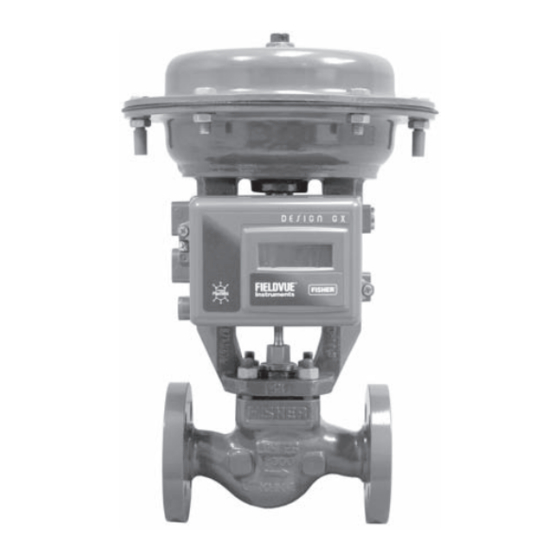
W8861
Figure 1. Design GX Control Valve, Actuator, and
FIELDVUEr DVC2000 Series Digital Valve Controller
The Design GX is rugged, reliable, and easy to
select. It requires no actuator sizing -- the actuator
selection is automatic once the valve body
construction is selected.
The Design GX meets the requirements of both EN
and ASME standards. It is available with a complete
accessory package, including the FIELDVUE
DVC2000 Series integrated digital valve controller.
Neither Emersonr, Emerson Process
Management, Fisherr, nor any of their
affiliated entities assumes
responsibility for the selection, use
and maintenance of any product.
Responsibility for the selection, use,
and maintenance of any product
remains with the purchaser and
end-user.
Note
Advertisement
Table of Contents

Related Manuals for Emerson FISHER GX


Summary of Contents for Emerson FISHER GX
-
Page 1: Table Of Contents
DVC2000 Series integrated digital valve controller. and D carefully reading and understanding the contents of this manual. If you have any questions Note about these instructions contact your Emerson Neither Emersonr, Emerson Process Process Managementt sales office before Management, Fisherr, nor any of their proceeding. -
Page 2: Specifications
If you are not sure what might result if service conditions these conditions are you should exceed those for which the product contact your Emerson Process was intended. To avoid injury or Management sales office for more damage, provide a relief valve for over complete specifications. -
Page 3: Maintenance
Instruction Manual Form 5770 GX Valve and Actuator June 2006 3. Use accepted piping practices when installing the valve in the pipeline. Use a suitable gasket between the valve and the pipeline flanges. 4. If continuous operation is required during inspection or maintenance, install isolating valves on either side of the control valve with a bypass valve to control the flow while the control valve is receiving... -
Page 4: Actuator Maintenance
Instruction Manual Form 5770 GX Valve and Actuator June 2006 D Use lock-out procedures to be Actuator Disassembly (For Air-to-Open sure that the above measures stay in Constructions - see figures 15 or 16) effect while you work on the 1. - Page 5 Instruction Manual Form 5770 GX Valve and Actuator June 2006 remove the cap screw (key 14), actuator spacer Table 2. Design GX Maximum Rated Travel (key 13), actuator rod (key 22), and washer (key 15). TRAVEL NUMBER OF ACTUATOR SIZE CASING BOLTS 9.
- Page 6 Instruction Manual Form 5770 GX Valve and Actuator June 2006 seven installed radially around the diaphragm plate 13. Stroke the actuator rod until it contacts the stem (key 11). Seven small springs (key 12) should be adjuster nut (key 27) and install the stem connector installed inside the large springs (key 13) which are halves and travel indicator (keys 23, 24, and 26) with located radially around the diaphragm plate.
-
Page 7: Fieldvuer Dvc2000 Digital Valve Controller Mounting
Instruction Manual Form 5770 GX Valve and Actuator June 2006 5. Torque the cap screw (key 14) to the actuator rod 17, and 18), install the body nuts (key 7) and tighten (key 22) to 65.5 NSm (48.3 lbfSft) and lay this evenly using a cross-tightening procedure. - Page 8 Instruction Manual Form 5770 GX Valve and Actuator June 2006 FOR AIR-TO-OPEN, INSTALL THE O-RING BEFORE MOUNTING TO THE GX ACTUATOR B: INTEGRAL MOUNTING PNEUMATIC OUTPUT PORT (R1/8 PLUG) POLE PIECES A: EXTERNAL PNEUMATIC OUTPUT PORT (1/4-INCH NPT OR G1/4 PLUG) M8 MOUNTING BOLTS Figure 3.
-
Page 9: Packing Maintenance
Instruction Manual Form 5770 GX Valve and Actuator June 2006 D To convert from air-to-close to air-to-open Pneumatic tubing is not required because the air passages are internal to the actuator. (spring-to-close), remove the R1/8 pneumatic plug on the back of the DVC2000 housing and install an O-ring (Port B of figure 3). - Page 10 Instruction Manual Form 5770 GX Valve and Actuator June 2006 b. Remove the stem connector nut half (key 23), 4. Then loosen the valve-to-yoke gasketed joint by stem connector bolt half (key 24), and travel either rocking the actuator yoke or prying between indicator (key 26).
- Page 11 Instruction Manual Form 5770 GX Valve and Actuator June 2006 the actuator yoke may cause possible sleeve, and the other between the guide sleeve and damage to the valve plug and to the bonnet. Ensure the gasket seating surfaces are bellows.
- Page 12 Instruction Manual Form 5770 GX Valve and Actuator June 2006 SIZE DN150 SIZE DN15, 20, 25 SIZE DN40, 50, 80, 100 (6-Inch) (0.5, 0.75, 1-INCH) (1.5, 2, 3, 4-INCH) GE02918-5 Figure 4. Seat Ring Removal and Installation Tool Table 5. Seat Ring Removal and Installation Tool Dimensions Valve Size Inch 15, 20, 25...
-
Page 13: Valve Trim Maintenance
Instruction Manual Form 5770 GX Valve and Actuator June 2006 halves in the proper orientation so that when looking Table 7. Seat Ring Torque Requirements at the inside of the stem connector halves, the flats VALVE SIZE TORQUE are down and the beveled surfaces are up. Inch lbfSft 15, 20, 25... - Page 14 Instruction Manual Form 5770 GX Valve and Actuator June 2006 5. Use a wrench to unscrew the plug/stem assembly 2. Use a seat ring tool made according to the (key 3) from the stem extension (key 40) or from dimensions in figure 4 and table 5 to remove the bellows/stem assembly (key 49) as follows: seat ring (key 2) as follows: a.
- Page 15 Instruction Manual Form 5770 GX Valve and Actuator June 2006 a. Clean the body/yoke gasket seating surfaces CAUTION and install a new body/yoke gasket (key 5). In the following procedure, take b. Remove any protective tape or covering from precautions to ensure the valve plug the valve plug/stem assembly.
-
Page 16: Bellows Maintenance
Instruction Manual Form 5770 GX Valve and Actuator June 2006 Repair Nameplate CAUTION If required by the end-user, an optional repair nameplate is available for recording changes made To protect the valve plug seal ring (key to the valve trim during maintenance (see figure 23). 37) and to ensure it seals properly, be This nameplate can be ordered as a spare part, and careful not to scratch the surfaces of the... -
Page 17: Handwheel Operation
Instruction Manual Form 5770 GX Valve and Actuator June 2006 LOCKING SCREW LOCKING SCREW STUD AND STUD AND NUT (4) NUT (4) GE11642-1 AIR-TO-CLOSE, SPRING-TO-OPEN AIR-TO-OPEN, SPRING-TO-CLOSE Figure 5. Design GX Handwheel Assembly ACTUATOR ACTUATOR OPERATING LEVER (2) STEM CONNECTOR APPLY LITHIUM GREASE... - Page 18 Instruction Manual Form 5770 GX Valve and Actuator June 2006 damage due to overtravel, the handwheel should not WARNING be turned more than 2 full turns past the point at which the levers no longer contact the stem connector. To avoid personal injury or equipment damage due to possible sudden shifting or falling of the valve assembly, do not lift the valve...
- Page 19 Instruction Manual Form 5770 GX Valve and Actuator June 2006 APPLY LUBRICANT GE03755_8 GE07161-D Figure 7. Design GX Balanced Trim Figure 9. Design GX Unbalanced Port-Guided Trim (Standard for Sizes DN 80 and 100 [3- and 4-Inch]) (Sizes DN 40 to 150 [1.5 to 6-Inch]) APPLY LUBRICANT APPLY LUBRICANT GE17575-C...
- Page 20 Instruction Manual Form 5770 GX Valve and Actuator June 2006 W9023-1 Figure 11. Design GX Control Valve with Typical Soft Seat GE11961_C Trim Construction (Port Sizes of 36mm - 136mm) Figure 13. Design GX Graphite ULF Packing DN15 through DN100 (0.5 through 4-Inch) GE03755_23 GE03755_14 Figure 12.
- Page 21 Instruction Manual Form 5770 GX Valve and Actuator June 2006 AIR SUPPLY CONNECTION GE02171-E Figure 15. Design GX Control Valve and Actuator System Assembly, Air-to-Open (Spring-to-Close) (Size DN25 (1-inch) with Unbalanced Contoured Plug)
- Page 22 Instruction Manual Form 5770 GX Valve and Actuator June 2006 AIR SUPPLY CONNECTION GE17517-C Figure 16. Design GX Control Valve and Actuator System Assembly, Air-to-Open (Spring-to-Close) (Size DN150 (6-inch) with Unbalanced Contoured Plug)
- Page 23 Instruction Manual Form 5770 GX Valve and Actuator June 2006 AIR SUPPLY CONNECTION GE03515-E Figure 17. Design GX Control Valve and Actuator System Assembly, Air-to-Close (Spring-to-Open) (Size DN25 (1-inch) with Unbalanced Contoured Plug)
- Page 24 Instruction Manual Form 5770 GX Valve and Actuator June 2006 AIR SUPPLY CONNECTION GE23239-B Figure 18. Design GX Control Valve and Actuator System Assembly, Air-to-Close (Spring-to-Open) (Size DN150 (6-inch) with Unbalanced Contoured Plug)
- Page 25 Instruction Manual Form 5770 GX Valve and Actuator June 2006 STEM EXTENSION HEX FLATS GF00337-D DO NOT APPLY LUBRICANT APPLY LUBRICANT Figure 19. Extension Bonnet with Graphite ULF Packing...
- Page 26 Instruction Manual Form 5770 GX Valve and Actuator June 2006 STEM EXTENSION HEX FLATS GF00338-D Figure 20. Bellows Extension Bonnet with PTFE Packing...
- Page 27 Instruction Manual Form 5770 GX Valve and Actuator June 2006 C HEX C HEX 8 mm 6 mm SIZE DN80 and 100 SIZE DN15, 20, 25, 40, and 50 (3 and 4-Inch) (0.5, 0.75, 1, 1.5, and 2-Inch) GF00536_3 Figure 21. Bellows Nut Removal and Installation Tool Table 10.
- Page 28 Instruction Manual Form 5770 GX Valve and Actuator June 2006 APPLY LUBRICANT GE05809_C Figure 22. Handwheel Assembly...
-
Page 29: Parts Ordering
35, not shown). The nameplate will normally performance of the valve, and might be fitted to the actuator. Refer to this serial number jeopardize worker and workplace when contacting your Emerson Process safety. Management sales office for technical assistance. Note... -
Page 30: Parts Kits
Instruction Manual Form 5770 GX Valve and Actuator June 2006 Parts Kits DN 25, 40, and 50 DN 80 and 100 DN 150 Valve Size (1, 1.5, and 2-Inch) (3- and 4-Inch) (6-Inch) Stem Diameter PACKING 10 mm 14 mm 19 mm KITS PTFE packing (Contains keys 32 and 33) -
Page 31: Parts List
Parts List Description Anti-Extrusion Washer (2 req’d) PTFE Packing Set Belleville Spring (3 req’d) Note Nameplate Warning Tag For part numbers not shown, contact your Emerson Seal Ring Process Management sales office. Backup Ring Extension Bonnet Description Part Number Stem Extension... - Page 32 Instruction Manual Form 5770 GX Valve and Actuator June 2006 Key 3 Valve Plug/Stem and Key 2 Seat Ring (Plain Bonnet, WCC/1.0619 and CF3M/1.4409 Valve Body Material) VALVE PORT VALVE SEAT SEAT RING TRAVEL PLUG/STEM VALVE SIZE PLUG STEM TRIM STYLE PLUG RING PART...
- Page 33 Instruction Manual Form 5770 GX Valve and Actuator June 2006 Key 3 Valve Plug/Stem and Key 2 Seat Ring (Plain Bonnet, WCC/1.0619 and CF3M/1.4409 Valve Body Material) VALVE PORT VALVE SEAT SEAT RING TRAVEL PLUG/STEM VALVE PLUG STEM SIZE TRIM STYLE PLUG RING PART...
- Page 34 Instruction Manual Form 5770 GX Valve and Actuator June 2006 Key 3 Valve Plug/Stem and Key 2 Seat Ring (Plain Bonnet, WCC/1.0619 and CF3M/1.4409 Valve Body Material) VALVE PORT VALVE SEAT SEAT RING TRAVEL PLUG/STEM VALVE PLUG STEM SIZE TRIM STYLE PLUG RING PART...
- Page 35 Instruction Manual Form 5770 GX Valve and Actuator June 2006 Key 3 Valve Plug/Stem and Key 2 Seat Ring (Plain Bonnet, WCC/1.0619 and CF3M/1.4409 Valve Body Material) VALVE PORT VALVE SEAT SEAT RING TRAVEL PLUG/STEM VALVE PLUG STEM SIZE TRIM STYLE PLUG RING PART...
- Page 36 Instruction Manual Form 5770 GX Valve and Actuator June 2006 Key 3 Valve Plug/Stem and Key 2 Seat Ring (Plain Bonnet, WCC/1.0619 and CF3M/1.4409 Valve Body Material) VALVE PORT VALVE SEAT SEAT RING TRAVEL PLUG/STEM VALVE PLUG STEM SIZE TRIM STYLE PLUG RING PART...
- Page 37 Instruction Manual Form 5770 GX Valve and Actuator June 2006 Key 3 Valve Plug/Stem and Key 2 Seat Ring (Plain Bonnet, WCC/1.0619 and CF3M/1.4409 Valve Body Material) VALVE PORT VALVE SEAT SEAT RING TRAVEL PLUG/STEM VALVE PLUG STEM SIZE TRIM STYLE PLUG RING PART...
- Page 38 Instruction Manual Form 5770 GX Valve and Actuator June 2006 Key 3 Valve Plug/Stem and Key 2 Seat Ring (Plain Bonnet, WCC/1.0619 and CF3M/1.4409 Valve Body Material) VALVE PORT VALVE SEAT SEAT RING TRAVEL PLUG/STEM VALVE PLUG STEM SIZE TRIM STYLE PLUG RING PART...
- Page 39 Instruction Manual Form 5770 GX Valve and Actuator June 2006 Key 3 Valve Plug/Stem and Key 2 Seat Ring (Plain Bonnet, CD3MN Valve Body Material) VALVE PORT VALVE SEAT SEAT RING TRAVEL PLUG/STEM VALVE PLUG STEM SIZE TRIM STYLE PLUG RING PART PART...
- Page 40 Instruction Manual Form 5770 GX Valve and Actuator June 2006 Key 3 Valve Plug/Stem and Key 2 Seat Ring (Plain Bonnet, CD3MN Valve Body Material) VALVE PORT VALVE SEAT SEAT RING TRAVEL PLUG/STEM VALVE PLUG STEM SIZE TRIM STYLE PLUG RING PART PART...
- Page 41 Instruction Manual Form 5770 GX Valve and Actuator June 2006 Key 3 Valve Plug/Stem and Key 2 Seat Ring (Plain Bonnet, CF3 Valve Body Material) VALVE PORT VALVE SEAT SEAT RING TRAVEL PLUG/STEM VALVE SIZE PLUG STEM TRIM STYLE PLUG RING PART PART...
- Page 42 Instruction Manual Form 5770 GX Valve and Actuator June 2006 Key 3 Valve Plug/Stem and Key 2 Seat Ring (Plain Bonnet, CF3 Valve Body Material) VALVE PORT VALVE SEAT SEAT RING TRAVEL PLUG/STEM VALVE SIZE PLUG STEM TRIM STYLE PLUG RING PART PART...
- Page 43 Instruction Manual Form 5770 GX Valve and Actuator June 2006 Key 3 Valve Plug/Stem and Key 2 Seat Ring (Plain Bonnet, CN7M and CW2M Valve Body Material) VALVE PORT VALVE SEAT SEAT RING TRAVEL PLUG/STEM VALVE PLUG STEM SIZE TRIM STYLE PLUG RING PART...
- Page 44 Instruction Manual Form 5770 GX Valve and Actuator June 2006 Key 3 Valve Plug/Stem and Key 2 Seat Ring (Plain Bonnet, CN7M and CW2M Valve Body Material) VALVE PORT VALVE SEAT SEAT RING TRAVEL PLUG/STEM VALVE SIZE PLUG STEM TRIM STYLE PLUG RING PART...
- Page 45 Instruction Manual Form 5770 GX Valve and Actuator June 2006 Key 3 Valve Plug/Stem and Key 2 Seat Ring (Extension Bonnet, WCC/1.0619 and CF3M/1.4409 Valve Body Material) VALVE PORT VALVE SEAT SEAT RING TRAVEL PLUG/STEM VALVE PLUG STEM SIZE TRIM STYLE PLUG RING PART...
- Page 46 Instruction Manual Form 5770 GX Valve and Actuator June 2006 Key 3 Valve Plug/Stem and Key 2 Seat Ring (Extension Bonnet, WCC/1.0619 and CF3M/1.4409 Valve Body Material) VALVE PORT VALVE SEAT SEAT RING TRAVEL PLUG/STEM VALVE PLUG STEM SIZE TRIM STYLE PLUG RING PART...
- Page 47 Instruction Manual Form 5770 GX Valve and Actuator June 2006 Key 3 Valve Plug/Stem and Key 2 Seat Ring (Extension Bonnet, WCC/1.0619 and CF3M/1.4409 Valve Body Material) VALVE PORT VALVE SEAT SEAT RING TRAVEL PLUG/STEM VALVE SIZE PLUG STEM TRIM STYLE PLUG RING PART...
- Page 48 Instruction Manual Form 5770 GX Valve and Actuator June 2006 Key 3 Valve Plug/Stem and Key 2 Seat Ring (Bellows Bonnet, WCC/1.0619 and CF3M/1.4409 Valve Body Material) VALVE PORT VALVE SEAT SEAT RING TRAVEL PLUG/STEM VALVE PLUG STEM SIZE TRIM STYLE PLUG RING PART...
- Page 49 Instruction Manual Form 5770 GX Valve and Actuator June 2006 Key 3 Valve Plug/Stem and Key 2 Seat Ring (Bellows Bonnet, WCC/1.0619 and CF3M/1.4409 Valve Body Material) VALVE PORT VALVE SEAT SEAT RING TRAVEL PLUG/STEM VALVE PLUG STEM SIZE TRIM STYLE PLUG RING PART...
- Page 50 Instruction Manual Form 5770 GX Valve and Actuator June 2006 Key 3 Valve Plug/Stem and Key 2 Seat Ring (Bellows Bonnet, WCC/1.0619 and CF3M/1.4409 Valve Body Material) VALVE PORT VALVE SEAT SEAT RING TRAVEL PLUG/STEM VALVE PLUG STEM SIZE TRIM STYLE PLUG RING PART...
- Page 51 Instruction Manual Form 5770 GX Valve and Actuator June 2006 Key 3 Valve Plug/Stem and Key 2 Seat Ring (Bellows Bonnet, WCC/1.0619 and CF3M/1.4409 Valve Body Material) VALVE PORT VALVE SEAT SEAT RING TRAVEL PLUG/STEM VALVE PLUG STEM SIZE TRIM STYLE PLUG RING PART...
- Page 52 Instruction Manual Form 5770 GX Valve and Actuator June 2006 Key 3 Valve Plug/Stem and Key 2 Seat Ring (Bellows Bonnet, CW2M Valve Body Material) VALVE PORT VALVE SEAT SEAT RING TRAVEL PLUG/STEM VALVE PLUG STEM SIZE TRIM STYLE PLUG RING PART PART...
- Page 53 Instruction Manual Form 5770 GX Valve and Actuator June 2006 Key 3 Valve Plug/Stem and Key 2 Seat Ring (Bellows Bonnet, CW2M Valve Body Material) VALVE PORT VALVE SEAT SEAT RING TRAVEL PLUG/STEM VALVE PLUG STEM SIZE TRIM STYLE PLUG RING PART PART...
- Page 54 Instruction Manual Form 5770 GX Valve and Actuator June 2006...
- Page 55 Instruction Manual Form 5770 GX Valve and Actuator June 2006...
- Page 56 Emerson Electric Co. Emerson Process Management, Emerson, and the Emerson logo are trademarks and service marks of Emerson Electric Co. All other marks are the property of their respective owners. This product may be covered by one or more of the following patents: 6,866,244;...
- Page 57 Form 5770, June 2006 Note The restricted travel position is set through use of the two adjustable cap screws on the lever. The r , Emerson Process Neither Emerson cover plate assembly is provided to eliminate the r , nor any of their Managementt, Fisher possibility of pinch points.
- Page 58 Errata Sheet September 2006 ADJUSTABLE CAP SCREW (2) LEVER COVER PLATE COVER PLATE LEVER ADJUSTABLE STUD AND CAP SCREW CAP SCREW STUD AND CAP SCREW (2) NUT (4) NUT (4) UPSTOP DOWNSTOP Figure 1. Design GX Travel Stop Assembly ACTUATOR ACTUATOR BRACKET LEVER...
- Page 59 Errata Sheet September 2006 Replacing Packing flat), as detected by a rapid increase in nut torque. This section of this errata sheet contains the following updates. b. For DN 15 through DN 100 (1/2 through 4-inch), loosen the packing follower 60_ of D Page 11, procedure 21 b, degree of loosening rotation.
- Page 60 Fisher is a mark owned by Fisher Controls International LLC, a member of the Emerson Process Management business division of Emerson Electric Co. Emerson Process Management, Emerson, and the Emerson logo are trademarks and service marks of Emerson Electric Co.
Need help?
Do you have a question about the FISHER GX and is the answer not in the manual?
Questions and answers