Table of Contents
Advertisement
Quick Links
Instruction Manual
D100345X012
August 2020
1805 Series Relief Valves
!
Failure to follow these instructions or
to properly install and maintain this
equipment could result in an explosion
and/or fire causing property damage and
personal injury or death.
Fisher™ relief valves must be installed,
operated and maintained in accordance
with federal, state and local codes, rules
and regulations, and Emerson Process
Management Regulator Technologies,
Inc. instructions.
If a leak develops or if the outlet
continually vents gas, service to the unit
may be required.
Failure to correct trouble could result in
a hazardous condition. Only a qualified
person must install or service the unit.
Call a gas service person to service the
unit. Only a qualified person must install
or service the 1805 Series Relief Valves.
Introduction
Scope of the Manual
This Instruction Manual provides installation,
adjustment, maintenance and parts ordering
information for 1805 Series relief valves.
WARNING
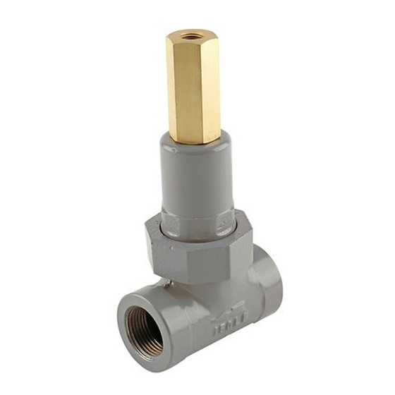
P1026
Figure 1. 1805 Series Relief Valve
Description
The 1805 Series relief valves are primarily designed
for use in farm tap applications where a safety relief
valve is needed between the first and second stage
regulators. The 1805 Series is suitable for service on
natural gas, air, propane or any operating medium that
is not corrosive to the internal parts. Relief pressure
ranges from 5 to 125 psi / 0.34 to 8.6 bar. Maximum
pressure, including buildup, is 150 psi / 10.3 bar.
1805 Series
Advertisement
Table of Contents

Subscribe to Our Youtube Channel
Related Manuals for Emerson 1805 Series


Summary of Contents for Emerson 1805 Series
- Page 1 Scope of the Manual valve is needed between the first and second stage regulators. The 1805 Series is suitable for service on This Instruction Manual provides installation, natural gas, air, propane or any operating medium that adjustment, maintenance and parts ordering is not corrosive to the internal parts.
-
Page 2: Specifications
1805 Series Specifications The Specifications section lists the specifications for the 1805 Series relief valve. The following information is stamped on the relief valve at the factory: type number, date of manufacture, spring range, maximum inlet pressure and maximum allowable inlet pressure. -
Page 3: Principle Of Operation
When upstream pressure registered on the diaphragm decreases to a level In the 1805 Series relief valves, the upstream pressure below that of the spring setting of the relief valve, the registers underneath the diaphragm. Gas reaches... -
Page 4: Installation
1805 Series TYPE CS200IN TEST GAUGE CONNECTION PLUGGED-OPTIONAL SET AT 8 IN. W.C. / 20 mbar TYPE 1805 SET AT 40 psi / 2.8 bar ROTATE PIPING SO DISCHARGE FROM RELIEF VALVE MISSES REGULATOR TYPE R622 ASSEMBLY OR 4 SET AT 25 psi / 1.7 bar... -
Page 5: Maintenance
The relief valve should O-rings and diaphragm. The 1805 Series relief valves be inspected for damage regularly and after any do not have to be removed from the pipeline to inspect overpressure condition. - Page 6 1805 Series BE9481 Figure 4. Type 1805-3 Relief Valve Assembly (Also typical of Type 1805 Relief Valves)
-
Page 7: Parts List
1805 Series Parts List Description Part Number Description Part Number Cap Screw, Zinc-plated steel Parts kit (included are keys 3, 5 and 8) 3/4 and 1 NPT body sizes 1B290524052 1-1/2 and 2 NPT body sizes 1E760324052 3/4 and 1 NPT body sizes... - Page 8 Technologies, Inc. All rights reserved. 08/20. Emerson Automation Solutions The Emerson logo is a trademark and service mark of Emerson Electric Co. All other marks are the property of their prospective owners. Fisher™ is a mark owned by Fisher Controls International LLC, a business...
Need help?
Do you have a question about the 1805 Series and is the answer not in the manual?
Questions and answers