
Related Manuals for INVT XG3-10KTL


Summary of Contents for INVT XG3-10KTL
- Page 1 User Manual XG3-10KTL Grid-tied Solar Inverter INVT Solar Technology (Shenzhen) Co., Ltd.
- Page 2 Preface The manual is intended to provide detailed information of product, installation, application, trouble shooting, precautions and maintenance of iMars series grid-tied solar inverter. The manual does not contain all the information of photovoltaic system. Please read this manual carefully and follow all safety precautions seriously before any moving, installation, operation and maintenance to ensure correct use and high performance of operation on the inverter.
-
Page 3: Table Of Contents
Grid-tied single-phase solar inverter Contents Contents Preface ................................i Contents ................................ii 1. Safety precautions ............................1 1.1Warning marks ..............................1 1.2 Safety guidance ..............................2 1.2.1 Transport and installation ........................3 1.2.2 Grid-connected operation ........................3 1.2.3 Maintenance and inspection .........................4 1.2.4 Waste disposal ............................4 2 Product overview ............................5 2.1 PV grid-connected power generation system ....................5 2.2 Product appearance ............................6... - Page 4 Grid-tied single-phase solar inverter Contents 5.2 Connect the protective ground wire ......................21 5.3 Connection of PV string ..........................22 5.4 Connection of DRM & CT ..........................24 5.5 Single-phase inverter grid access .........................25 6 Running ................................ 26 6.1 Inspection before running ..........................26 6.2 Inverter grid-connected running ........................26 6.3 Inverter stop ..............................
-
Page 5: Safety Precautions
Grid-tied single -phase solar inverter Safety precautions 1. Safety precautions iMars series grid-tied solar inverters are designed and tested strictly in accordance with relevant international safety standards. As an electrical and electronic device, all relevant safety regulations must be strictly complied during installation, operation, and maintenance. Incorrect use or misuse may result in: Injury to the life and personal safety of the operator or other people. -
Page 6: Safety Guidance
Grid-tied single -phase solar inverter Safety precautions 1.2 Safety guidance After receiving this product, first please confirm the product package is intact. If any question, please contact the logistic company or local distributor immediately. The installation and operation of PV inverter must be carried out by professional ... -
Page 7: Transport And Installation
Grid-tied single -phase solar inverter Safety precautions Operators need to be fully familiar with the composition and operating principle of the entire grid-tied photovoltaic power generation system and related standards of the countries/regions in which the project is located. ... -
Page 8: Maintenance And Inspection
Grid-tied single -phase solar inverter Safety precautions countries/regions in which the project is located. Ensure the inverter is installed firmly and electrical wiring is reliable before operating on the inverter. Do not open the inverter when it is running or connecting power ... -
Page 9: Product Overview
Grid-tied single -phase solar inverter Product overview 2 Product overview This chapter mainly introduces the appearance, package accessories, nameplate, technical parameters of the grid-connected inverter. 2.1 PV grid-connected power generation system PV grid-connected power generation system is comprised of solar battery component, grid-connected inverter and public grid. -
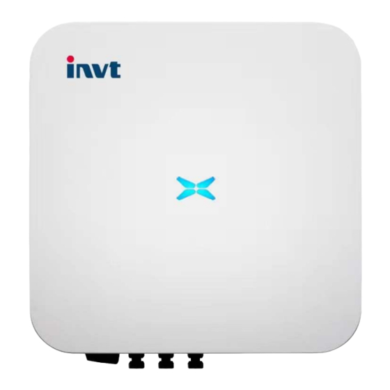
Page 10: Product Appearance
Grid-tied single -phase solar inverter Product overview 2.2 Product appearance Figure 2.3 Appearance of the single-phase PV inverter Table 2-1 Description of key exterior components of single-phase PV inverters Number Name Introduction DC switch Close/disconnect the PV array DC input interface Inverter DC input terminal, connected to the PV array Communication CT,DRM interface... -
Page 11: Nameplate Description
Grid-tied single -phase solar inverter Product overview 2.3 Nameplate description Figure 2.4 shows the inverter nameplate. Figure 2.4 Nameplate Trademarks and product types (1) Model and important technical parameters (2) Certification system of the inverter confirming, serial number, company name and country of (3)... -
Page 12: Product Model
Grid-tied single -phase solar inverter Product overview Icons Instruction TUV certification mark. The inverter is certified by TUV CE certification mark. The inverter complies with the CE directive CQC certification mark. The inverter passed CQC certification EU WEEE mark. The inverter cannot be disposed of as domestic waste ... -
Page 13: Outline Dimension And Weight
Grid-tied single -phase solar inverter Product overview 2.5 Outline dimension and weight Figure 2.5 Outline dimensions of the inverter Table 2-3 Dimensions and net weight of the inverter Model Height(mm) Width(mm) Depth(mm) Net weight(kg) XG5KTL XG8KTL 12.6 XG10KTL 13.0 Fig 2.6 Dimension of paper package Table 2-4 Dimension and gross weight Height Width... -
Page 14: The Led Light Panel
Grid-tied single -phase solar inverter Product overview 2.6 The LED light panel The LED indicator panel as the human-computer interaction interface, may indicate the working state of the inverter. 2.6.1 The LED light panel Figure 2.7 LED Front View LED indicator status description: Normal, grid-tied and generating Steady blue power... -
Page 15: Lcd Operation Panel
Grid-tied single -phase solar inverter Product overview 2.6.2 LCD operation panel Figure 2.8 LCD Front View Definition of LCD operation panel: ①”Run”, running status, shows green light; ②"Fault", the PV string is disconnected, shows red light; ③ Select upwards, short press to move upwards, long press to return;... -
Page 16: Bottom Of The Inverter
Grid-tied single -phase solar inverter Product overview 2.7 Bottom of the inverter XG3-10KTL is equipped with a DC switch that controls the DC terminal switch. Figure 2.9 without fan Figure 2.10 with fan(XG7KTL1, XG8KTL1, XG10KTL, XG10KTL1) -
Page 17: Inverter Storage
Grid-tied single -phase solar inverter Inverter storage 3 Inverter storage If the inverter is not put into use immediately, the storage of inverter should meet the following requirements: Do not remove the inverter outer package. The inverter needs to be stored in a clean and dry place, and to prevent the erosion of dust and ... -
Page 18: Installation
Grid-tied single -phase solar inverter Installation 4 Installation This chapter introduces the installation of the inverter and the connection of the inverter to the PV power generation system. Connecting inverters to PV power generation systems mainly involves the PV strings and public grids connect to the inverter. Please read this chapter carefully before installation, and ensure that all installation conditions are met by professional technicians to complete the inverter installation. - Page 19 Grid-tied single -phase solar inverter Installation Fig4.1 Delivery content of single-phase inverter 3-10kW Table 4-1 delivery contents of three-phase inverter Number Name Quantity Inverter Mounting bracket AC side quick connect terminal CT,DRM Connect the terminals DC connector (pair) User manual Stainless Steel Expansion Bolts M6*50 M6 combination bolt...
-
Page 20: Prepare Before Installation
Grid-tied single -phase solar inverter Installation 4.2 Prepare before installation 4.2.1 Installation tool Table 4-2 List of installation tools Number Installation tools instruction Marker pen Mark the mounting holes Electric drill Drill holes in the bracket or wall Hand hammer Knock the expansion bolt Adjustable wrench For fixed mounting bracket... -
Page 21: Space Requirements
Grid-tied single -phase solar inverter Installation (6) The installation environment temperature is - 30 ℃ ~ 60 ℃; (7) The installation site should be far away from the electronic equipment with strong electromagnetic interference; (8) The installation site should be fixed and solid object surface, such as wall, metal support, etc; (9) The installation position shall ensure the reliable grounding of the inverter, and the grounding metal conductor material shall be consistent with the reserved grounding metal material of the inverter. -
Page 22: Mounting Board Size
Grid-tied single -phase solar inverter Installation (3) When installing multiple inverters, a certain distance shall be reserved between the inverters, as shown in Figure 4.4. At the same time, sufficient distance shall be reserved between the upper and lower parts of the inverter to ensure good heat dissipation。 Fig 4.5 Size requirements for side-by-side installation (4) The installation surface should be perpendicular to the horizontal line, as shown in Figure 4.5. -
Page 23: Wall Installation
Grid-tied single -phase solar inverter Installation 4.5 Wall installation Step 1:Place the hanging board on the wall mounting point, use a level to adjust the angle, and mark with a marker. Step 2: Use a hammer drill to drill holes and install expansion bolts. Use M6×50 stainless steel pressure explosion expansion bolts. - Page 24 Grid-tied single -phase solar inverter Installation hoisting ring and rope. After confirming that the connection is secure, lift the inverter to the destination. Step 3: After lifting the inverter, buckle the bracket plate on the back of the machine into the wall-mounting plate, and make sure that the machine bracket plate fits well with the groove of the hanging plate.
-
Page 25: Electrical Connection
Grid-tied single -phase solar inverter Electrical connection 5 Electrical connection 5.1 Overview of electrical connections This section will introduce the electrical connection related content and related safety precautions in detail. ig 5.1 Schematic diagram of PV grid-connected system connection Electrical connections must be completed by professional worker. Wrong ... -
Page 26: Connection Of Pv String
Grid-tied single -phase solar inverter Electrical connection Fig 5.2 PV grounding diagram The inverter must be grounded through the side screws to ensure reliable grounding and reliable lightning protection. 5.3 Connection of PV string Step 1: Connect the outlet line of the PV panel to the MC4 terminal delivered by the machine The MC4 terminal crimping method is as follows: (1) As shown in Fig 5.2, connect the output wire of the PV string to the DC connector of the inverter. - Page 27 Grid-tied single -phase solar inverter Electrical connection string, verify the polarity of the DC input cable, and ensure that the voltage of each string is within the allowable range of the inverter, as shown in Fig 5.3. Fig 5.4 Measuring DC input voltage The PV string connected to iMars series inverter must adopt the DC connector ...
-
Page 28: Connection Of Drm & Ct
Grid-tied single -phase solar inverter Electrical connection 5.4 Connection of DRM & CT The picture of DRM & CT connector is as follows: Fig 5.6 DRM & CT connector side view Fig 5.7 DRM & CT connector Front view Table 5-1 The DRM & CT connector Signal description Pin NO. -
Page 29: Single-Phase Inverter Grid Access
Grid-tied single -phase solar inverter Electrical connection 5.5 Single-phase inverter grid access Table 5-2 Single-phase photovoltaic inverter AC connector interface description Inverter AC connector Single-phase grid Remarks interface live wire neutral line PE ground wire Must be connected 5.5.1 Connection terminal grid access (1) According to Table 5-1, the three conductors of single-phase public power grid L, N and PE are correctly connected to the corresponding holes according to the identification, and ensure that the conductors are not exposed and crimped firmly, and finally tighten the waterproof cap, as shown in Fig... -
Page 30: Running
Grid-tied single -phase solar inverter Running 6 Running This chapter introduces the related operations during the use of the inverter, which mainly involves pre-operation inspections, grid-connected operation of the inverter, inverter shutdown, and precautions for daily maintenance and repair of the inverter. 6.1 Inspection before running The following items must be checked strictly before running the PV grid-connected inverter (including but not limited to the following items):... -
Page 31: Inverter Stop
Grid-tied single -phase solar inverter Running (6) Wait for the inverter to connect to the grid successfully. 6.3 Inverter stop When it is necessary to perform power failure maintenance, overhaul, and troubleshooting of the inverter, please strictly follows the steps below to shut down the inverter: (1) Disconnect the AC side circuit breaker of the inverter public grid;... -
Page 32: Maintenance Guidance
Grid-tied single -phase solar inverter Running Maintenance Check Item Inspection Method Cycle Check whether the system cable connection is loose, whether the inverter wiring terminal is loose, and then Electrical tighten it according to the method specified in section 4. Once per half connections a year... - Page 33 Grid-tied single -phase solar inverter Running Step 1: Stop the inverter and disconnect the electrical connection. (1) Disconnect the input and output connections. (2) Turn the DC switch to the "OFF" position. (3) Wait ten minutes. (4) Disconnect all electrical connections at the bottom of the inverter. Step 2: Disconnect the fan power plug and remove the fan cover at the bottom of the chassis.
-
Page 34: Troubleshooting
Grid-tied single -phase solar inverter Troubleshooting 7 Troubleshooting This chapter introduces fault alarms and codes, which are used to quickly find inverter faults. Table 7-1 Inverter fault codes Fault Number Fault types Fault information Solution code Check wether the PV 01-01 Low PV voltage terminal is plugged in... - Page 35 Grid-tied single -phase solar inverter Troubleshooting Fault Number Fault types Fault information Solution code 09-04 DSP2 SPI fault 09-05 DSP1 and MCU SCI fault The static leakage current 10-01 Check whether the panel is high wiring terminals have 10-02 30mA mutation failure Leakage entered the water, or are current fault...
- Page 36 Grid-tied single -phase solar inverter Troubleshooting Table 7-2 Inverter warning code Alarm Number Alarm types Alarm information Display information code 01-01 Fan1 01-02 Fan2 Fan speed is Please contact customer service 01-03 Fan3 01-04 Fan4 Lightning Please contact customer 02-01 Lightning protector protector service...
- Page 37 Grid-tied single -phase solar inverter Troubleshooting If any problem, please contact with the supplier and provide following information: Model of the inverter: Serial No. of the inverter: System version: ——version 1: ——version 2: ——MCU software version: Fault code: ...
-
Page 38: Contact Information
Contact information Grid-tied single -phase solar inverter 8 Contact information China·Shenzhen INVT Solar Technology (Shenzhen) Co., Ltd. Address: 2nd Floor, Block B, Yingweiteng Guangming Technology Building, Songbai Road, Matian Street, Guangming District, Shenzhen Service Hotline: +86 400 700 9997 Email: solar-service@invt.com.cn INVT website: www.invt.com... -
Page 39: Appendix
Grid-tied single -phase solar inverter Appendix 9 Appendix Table 9-1 Technical parameters of single-phase PV grid-connected inverter Technical specifications XG3KTL-2M XG4KTL XG5KTL XG6KTL XG7KTL XG7KTL1 XG8KTL XG8KTL1 XG10KTL XG10KTL1 DC side Maximum input 4500W 6000W 7500W 9000W 10500W 10500W 12000W 12000W 15000W 15000W... - Page 40 Service Hotline: +86 400 700 9997 Email: solar-service@invt.com.cn website: www.invt-solar.com INVT Solar Technology (Shenzhen) Co., Ltd.. 2nd Floor, Block B, Yingweiteng Guangming Technology Building, Songbai Road, Matian Information may be subject to change without notice during product improving 202212(V1.0)
Need help?
Do you have a question about the XG3-10KTL and is the answer not in the manual?
Questions and answers