Table of Contents
Advertisement
Quick Links
Advertisement
Table of Contents

Subscribe to Our Youtube Channel
Related Manuals for Zte ZXSDR BS8800 C200


Summary of Contents for Zte ZXSDR BS8800 C200
- Page 1 ZXSDR BS8800 C200 CDMA Indoor Basestation-8800 Installation Manual ZTE CORPORATION ZTE Plaza, Keji Road South, Hi-Tech Industrial Park, Nanshan District, Shenzhen, P. R. China 518057 Tel: (86) 755 26771900 Fax: (86) 755 26770801 URL: http://ensupport.zte.com.cn E-mail: support@zte.com.cn...
- Page 2 The contents of this document are protected by copyright laws and international treaties. Any reproduction or distribution of this document or any portion of this document, in any form by any means, without the prior written consent of ZTE CORPO- RATION is prohibited.
-
Page 3: Table Of Contents
Contents Preface............... i Safety Instruction ..........1 Safety Specifications Guide ..........1 Safety Symbols .............. 2 Safety Instructions ............3 Installation Overview ........7 Appearance ..............7 Engineering Indices ............7 Installation Flow ............. 8 Installation Precautions ........... 9 Installation Preparation ........11 Cabinet Installation Environment Check ......11 Equipment Room Space Requirements......11 Equipment Room Environment Requirements ....13... - Page 4 Installing RSU Module ............33 Installing BBU ...............35 Installing BBU Horizontal Module ........37 Installing BBU Vertical Module .........38 Installing Cable ..........41 On-site Cable Installation List..........41 Cable Installation Flow ...........42 Installing DC Power Cable ..........43 Installing Grounding Cable ..........46 Installing Data Cable............47 Installing 75Ω...
- Page 5 Hoisting Antenna and Feeder ........89 Installing Indoor Grounding Bar........90 Installing Antenna ............93 Installing Directional Antenna on Top-tower ....93 Installing Directional Antenna on Roof ......100 Installing Omnidirectional Antenna on Top-tower..111 Installing Omnidirectional Antenna on Roof ....115 Installing Antenna Jumper ........123 Installing Feeder Hermetic-window ........
- Page 6 List of Glossary..........159...
-
Page 7: Preface
Preface The ZXSDR BS8800 C200 is a radio transceiver device to provide Purpose service for a certain cell. The ZXSDR BS8800 C200 can fulfill most functions concerning CDMA patent technologies. The pri- mary functions of ZXSDR BS8800 C200 are: baseband modulation... - Page 8 GPS Antenna Feeder System Chapter 8 Describes the installation methods of main antenna Installing feeder system. Main Antenna Feeder System Chapter 9 Describes the inspection process after installation Installation completion. Check Confidential and Proprietary Information of ZTE CORPORATION...
-
Page 10: Safety Symbols
ZXSDR BS8800 C200 Installation Manual Note: ZTE Corporation does not bear any liabilities incurred because of violation of the universal safety operation requirements, or viola- tion of safety standards for designing, manufacturing and using the equipment. Safety Symbols Table 1 lists safety symbols. -
Page 11: Safety Instructions
Do not wear any watch, hand chain, bracelet, ring or any � other conductive object during such operations. Prevent moisture from accumulating on the equipment dur- � ing operations in a damp environment. � Power Cable Confidential and Proprietary Information of ZTE CORPORATION... - Page 12 30 kV, and can remain in there for a long time. An operator with static electricity may discharge electricity through a component when he/she touches the conductor and causing damage. Confidential and Proprietary Information of ZTE CORPORATION...
- Page 13 Plug the module right into the slot and make sure module cir- cuit faces do not contact each other lest any short circuit may occur. � Keep hands off the module circuit, components, connectors and cable trough when holding a module. Confidential and Proprietary Information of ZTE CORPORATION...
- Page 14 Due to that RRU is in high temperature during running, the RRU should be installed in some regions out of operators’ reach or strictly restricted. � Contact ZTE office if you have any question, to ensure your safety. Confidential and Proprietary Information of ZTE CORPORATION...
-
Page 15: Installation Overview
Installation Precautions ............9 Appearance Figure 1 shows the appearance of ZXSDR BS8800 C100. 1 ZXSDR BS8800 C200 A IGURE PPEARANCE Engineering Indices Table 2 lists the engineering indices of ZXSDR BS8800 C200. Confidential and Proprietary Information of ZTE CORPORATION... -
Page 16: Installation Flow
-40 ℃ to 55 ℃ (-40 ℉ to 131 ℉) Overall Power < 3000 W (full configuration) Consumption Working Humidity 5% RH ~ 95% RH < 5 Ω Grounding Installation Flow The ZXSDR BS8800 C200 installation flow is listed in Figure 2 Confidential and Proprietary Information of ZTE CORPORATION... -
Page 17: Installation Precautions
� ZXSDR BS8800 C200 hardware installation personnel must participate in some training related to communication equip- ment installation and own skilled installation technique. �... - Page 18 Take hold of the edge of boards and not touch the circuit, com- ponents and wires. � Replacing components or modifying devices may bring extra risks. Without authorization, prohibit replacing or modifying devices. Confidential and Proprietary Information of ZTE CORPORATION...
-
Page 19: Installation Preparation
Technical Material Preparation ..........17 Personnel Requirements .............18 Tools and Instruments Preparation ........18 Unpacking Acceptance............20 Cabinet Installation Environment Check Equipment Room Space Requirements The minimum installation space of cabinet is required as shown in Figure Confidential and Proprietary Information of ZTE CORPORATION... -
Page 20: Figure 3 Installation Space Requirement
100 mm from the both walls. � Keep a more than 800 mm space from the face of equipment. Confidential and Proprietary Information of ZTE CORPORATION... -
Page 21: Equipment Room Environment Requirements
� Select some material which is difficult to deform and crack for hidden pipes, holes and slots between cover plates. � Prepare a temporary room to store installation materials and devices. Confidential and Proprietary Information of ZTE CORPORATION... -
Page 22: Equipment Room Power Supply Requirements
The voltage range: 380 V±10%;220 V±10%. � The supply power voltage of DC distribution device should be stable and the nominal value is -48 V (-57 V~-40 V). � The battery capacity should be adequate. Confidential and Proprietary Information of ZTE CORPORATION... -
Page 23: Lightning And Grounding Requirements
All device grounding connects to this grounding bar. And then the grounding bar connects with the primary ground- ing bar of the building. Transmission Requirements The external interfaces of ZXSDR BS8800 C200 locate on the modules and subsystem, referring to Table... -
Page 24: Wiring Requirements
The rout of cable layout should be clear and reasonable, ac- cording to the engineering design drawing. � The layout of signal cable should be orderly, smooth and non- crossed. � The layout of cables should be convenient for maintenance and capacity expansion. Confidential and Proprietary Information of ZTE CORPORATION... -
Page 25: Technical Material Preparation
Technical Material Preparation It is necessary to prepare the following technical material for ZXSDR BS8800 C200 installation: � ZXSDR BS8800 C200 CDMA Indoor Basestation-8800 Engi- neering Survey Report � ZXSDR BS8800 C200 CDMA Indoor Basestation-8800 Environ- ment Acceptance Report ZXSDR BS8800 C200 kit materials include: �... -
Page 26: Personnel Requirements
ZXSDR BS8800 C200 CDMA Indoor Basestation-8800 Commis- sioning and Configuration Manual Personnel Requirements Installation personnel should participate in ZTE’s training and ex- amination, and handle knowledge of installation and debugging. After obtaining job certificate, installation personnel are qualified for installation and debugging. - Page 27 One hacksaw (with several saw blades) One pair of sharp-nose pliers (8″) One pair of diagonal pliers (8″) One pair of slip joint pliers (8″) One pair of vices (8″) Crowbar Auxiliary tools Chain wheel Rope Ladder Forklift Confidential and Proprietary Information of ZTE CORPORATION...
-
Page 28: Unpacking Acceptance
The steps involved in counting goods are as follows: 1. Check Delivery Checklist of ZTE Corporation. Check total num- Steps ber of goods, intactness of packing boxes, and check whether arrival place is the actual installation place against packing list number attached to packing boxes. -
Page 29: Carton Unpacking
1. Use diagonal pliers to cut packing straps. Steps 2. Use a paper knife to cut adhesive tape along the slits on carton cover, avoid damaging goods inside. 3. Open the carton, and remove the foam board. Confidential and Proprietary Information of ZTE CORPORATION... -
Page 30: Acceptance And Goods Handover
Unpacking for Inspection Report. If the goods are still un- der the supervision of the operator even after acceptance, then goods will not be handed over to the operator until both parties sign on the report. ND OF STEPS Confidential and Proprietary Information of ZTE CORPORATION... -
Page 31: Installing Cabinet
C h a p t e r Installing Cabinet Table of Contents: Cabinet Installation Flow ............23 Installing Single-cabinet .............24 Cabinet Installation Flow ZXSDR BS8800 C200 cabinet installation flow is listed in Figure Confidential and Proprietary Information of ZTE CORPORATION... -
Page 32: Installing Single-Cabinet
Make sure the hole positions for cabinet installation on the straight lines according to the design drawing. The position of single-cabinet is as shown in Figure Confidential and Proprietary Information of ZTE CORPORATION... -
Page 33: Figure 6 Single-Cabinet Installation Position
3. Install expansion nuts. Before installation, use the cleaner to get rid of all dust inside and outside holes. Confidential and Proprietary Information of ZTE CORPORATION... -
Page 34: Figure 8 Insulation Sleeve Installation
Figure 9 EXPANSION NUT INSTALLATION IGURE 4. Adjust an insulation sheet and align two holes on the insulation sheet with those on the ground, as shown in Figure 10 INSULATION SHEET INSTALLATION IGURE Confidential and Proprietary Information of ZTE CORPORATION... -
Page 35: Figure 11 Base Installation Assembly (1)
Adjust the multimeter to the resistance grade. ii. For resistance measurement, one measuring probe of the multimeter contacts with the metal part of base assembly and the other with the expansion nuts. If the circuit dis- Confidential and Proprietary Information of ZTE CORPORATION... -
Page 36: Figure 13 Fixing Cabinet (1)
Figure 13 FIXING CABINET (1) IGURE Location Hole Orientation Pin Bolt Angle Support Confidential and Proprietary Information of ZTE CORPORATION... -
Page 37: Figure 14 Fixing Cabinet (2)
The insulation washer has been riveted at the bottom of cabinet. 8. According to Step 6, perform a solution test for metal compo- nents at the front of cabinet. 9. Close the front door and fix the cabinet, as shown in Figure Confidential and Proprietary Information of ZTE CORPORATION... -
Page 38: Figure 15 Cabinet Installation Completion
ZXSDR BS8800 C200 Installation Manual 15 CABINET INSTALLATION COMPLETION IGURE ND OF STEPS Confidential and Proprietary Information of ZTE CORPORATION... -
Page 39: Installing Components
Installing BBU Horizontal Module .........37 Installing BBU Vertical Module ..........38 Module Position Schematic Diagram The main modules of ZXSDR BS8800 C200 are installed in the RF ZXSDR BS8800 C200 Baseband layer and baseband layer. The internal structure is as shown in... -
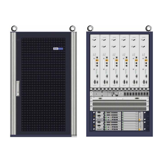
Page 40: Figure 16 Baseband-Rf Cabinet Internal Structure
ASEBAND ABINET NTERNAL TRUCTURE RF Subrack Fan Subrack Cable Tray Wind-guide Place Power Distribution Subrack Baseband Subrack The RF modules are configured in the first subrack, as shown in RF Module Layout Figure Confidential and Proprietary Information of ZTE CORPORATION... -
Page 41: Installing Rsu Module
Chapter 5 Installing Components 17 RF SUBRACK APPEARANCE IGURE RF Unit Six RSU multi-carrier RF units can be configured in Slot1~Slot6. ZXSDR BS8800 C200 baseband subrack is as shown in Figure Baseband Moudle Layout 18 BASEBAND SUBRACK APPEARANCE IGURE Installing RSU Module �... -
Page 42: Figure 19 Screw Positions On Rf Module
The positions of six screws are as shown in Figure 19 SCREW POSITIONS ON RF MODULE IGURE M5X20 pan head assembly screw 6. Screw down all screws as shown in Figure 20 and connect the RSU grounding sheet. Confidential and Proprietary Information of ZTE CORPORATION... -
Page 43: Installing Bbu
Prerequisite � Wear an antistatic wrist strap to avoid damaging the BBU. 1. Insert the module into the ZXSDR BS8800 C200 cabinet along Steps the guideway and fix it with four M5×16 combined screws (two respectively at left and right), as shown in... -
Page 44: Figure 21 Bbu Installation
2. Connect the grounding lug of BBU to the cabinet with a M6×16 screw. The position of M6×16 screw is as shown in Figure 22 M6×16 S IGURE CREW OSITION Grounding lug M6×16 screw Confidential and Proprietary Information of ZTE CORPORATION... -
Page 45: Installing Bbu Horizontal Module
� Fabric switch module(FS) � Site alarm module (SA) � Power module (PM) 1. Insert the modules into the ZXSDR BS8800 C200 subrack along Steps the left and right guideways, as shown in Figure 23 HORIZONTAL MODULE INSTALLATION IGURE Horizontal Insertion and Ex-... -
Page 46: Installing Bbu Vertical Module
ZXSDR BS8800 C200 Installation Manual 2. Hold handles at both sides of subrack to push into the module and make sure the handle locked with the ZXSDR BS8800 C200 subrack. ND OF STEPS Installing BBU Vertical Module Make sure wearing an antistatic wrist wrap in case of damaging Prerequisite the PCB board. -
Page 47: Figure 25 Vertical Module Installation
Chapter 5 Installing Components 3. Push the equipped FA subrack and dustproof assembly into the ZXSDR BS8800 C200 until hearing locking sound, as shown in Figure 25 V IGURE ERTICAL ODULE NSTALLATION ND OF STEPS Confidential and Proprietary Information of ZTE CORPORATION... - Page 48 ZXSDR BS8800 C200 Installation Manual This page is intentionally blank. Confidential and Proprietary Information of ZTE CORPORATION...
-
Page 49: Installing Cable
External power cable � Protective ground cable � E1/T1 external cable � Abis/Iub interface optical fiber � Abis/Iub interface Ethernet cable � Dry contact cable � RS232/RS485 cable � Antenna feeder and jumper Confidential and Proprietary Information of ZTE CORPORATION... -
Page 50: Cable Installation Flow
ZXSDR BS8800 C200 Installation Manual � jumper Cable Installation Flow The cable installation flow is listed in Figure 26 C IGURE ABLE NSTALLATION Confidential and Proprietary Information of ZTE CORPORATION... -
Page 51: Installing Dc Power Cable
1. Lay out the route and length of cables along a cable tray be- Prerequisite tween the power cabinet and the ZXSDR BS8800 C200. The power cable and the protective ground cable should be sepa- rately arranged and banded from other cables. The banding distance per segment is 200 mm. -
Page 52: Figure 28 Dc Power Cable Inlet
5. Install respectively the –48V DC (blue) and –48V RTN (black) cables to the connection terminals of the power distribution subrack, the connection relationship as shown in Figure Confidential and Proprietary Information of ZTE CORPORATION... -
Page 53: Figure 29 Power Distribution Subrack Connection
6. Refix the protective cover to the power distribution subrack. ND OF STEPS The installation of power cable is completed, as shown in Figure Result Confidential and Proprietary Information of ZTE CORPORATION... -
Page 54: Installing Grounding Cable
ZXSDR BS8800 C200 Installation Manual 30 P IGURE OWER ABLE NSTALLATION OMPLETION Installing Grounding Cable 1. Based on the distance from the cabinet to the protective Steps ground, cut a proper length of protective ground cable. Confidential and Proprietary Information of ZTE CORPORATION... -
Page 55: Installing Data Cable
SA module at End A of data cable. There are multiple tri-interface at End B, connecting the internal/exter- nal environment monitoring, dry contact monitoring and E1/T1. The exploded view of data cable is as shown in Figure Confidential and Proprietary Information of ZTE CORPORATION... -
Page 56: Figure 32 Data Cable Appearance
5. Connect End B4 to the DB25 connector of the external dry con- tact cable and screw down two bolts at the junction. ND OF STEPS The data cable is installed completely, as shown in Figure Result Confidential and Proprietary Information of ZTE CORPORATION... -
Page 57: Installing 75Ω E1 Cable
Install the SA module and its panel connection cable. Prerequisite Abis-interface 75 Ω E1 cable is the transmission cable between Context ZXSDR BS8800 C200 and BSC, transmitting the interface message between ZXSDR BS8800 C200 and BSC. The appearance of 75 Ω E1 cable is as shown in Figure 34. -
Page 58: Figure 34 Abis/Iub Interface 75 Ω E1 Cable Appearance
3. Connect the DB44 connector of 75 Ω E1 cable to the B2 inter- face (E1 cable interface) of data cable through the module. ND OF STEPS After installation completed, the appearance of 75 Ω E1 cable is Result as shown in Figure Confidential and Proprietary Information of ZTE CORPORATION... -
Page 59: Installing 120Ω E1 Cable
Chapter 6 Installing Cable 35 75 Ω E1 C IGURE ABLE NSTALLATION OMPLETION Installing 120Ω E1 Cable Install the module and data cable. Prerequisite Confidential and Proprietary Information of ZTE CORPORATION... -
Page 60: Installing 100Ω T1 Cable
The 120 Ω E1 cable is the transmission cable between ZXSDR Context BS8800 C200 and BSC, transmitting the interface message be- tween ZXSDR BS8800 C200 and BSC. The appearance of 120 Ω E1 cable is as shown in Figure 36. End A of cable is a DB44 straight plug. -
Page 61: Installing Abis Interface Ethernet Cable
The transmission between BTS and BSC is based on the IP Prerequisite bearer network. � Install the CC module. Both ends of Ethernet cable are crimped with the RJ45 connector, Context as shown in Figure Confidential and Proprietary Information of ZTE CORPORATION... -
Page 62: Figure 38 Ethernet Cable Appearance
1. Lead the Abis interface through a wire inlet at the right side of Steps cabinet. 2. Lay out the Abis interface Ethernet cable along the vertical ca- ble tray at the right side of cabinet to module of the base- band, as shown in Figure Confidential and Proprietary Information of ZTE CORPORATION... -
Page 63: Installing Dry Contact Input/Output Cable
ABLE AYOUT 3. Connect the RJ45 connector of Ethernet cable to the ETH0 in- terface on the module. ND OF STEPS Installing Dry Contact Input/output Cable Install the module and data cable. Prerequisite Confidential and Proprietary Information of ZTE CORPORATION... -
Page 64: Figure 40 Dry Contact Input/Output Cable Appearance
3. Connect the DB25 connector of dry contact cable to the B4 interface (DB25) of data cable from the module. ND OF STEPS After installation completed, the appearance of dry cable is as Result shown in Figure Confidential and Proprietary Information of ZTE CORPORATION... -
Page 65: Figure 41 Dry Contact Installation Completion
Chapter 6 Installing Cable 41 D IGURE ONTACT NSTALLATION OMPLETION Confidential and Proprietary Information of ZTE CORPORATION... -
Page 66: Installing Rs232/Rs485 Monitoring Cable
1. Connect End A (DB9 connector) of RS232/RS485 monitoring Steps cable to the B3 connector (DB9) of SA panel connection cable- data cable. 2. Fasten junctions of the connectors with tapes. ND OF STEPS Confidential and Proprietary Information of ZTE CORPORATION... -
Page 67: Installing Fiber Between Bbu And Rsu
Installing Fiber between BBU and RSU � Install the cabinet completely. Prerequisite � Install the ZXSDR BS8800 C200 and all modules. The appearance of ZXSDR BS8800 C200 optical fiber is as shown Context Figure 43 O IGURE PTICAL IBER PPEARANCE 1. -
Page 68: Figure 44 Aisg Control Cable Structure
TRUCTURE 1. Connect End A of AISG control cable to the debugging inter- Steps face (AISG) of ZXSDR BS8800 C200 and fasten screws of the interface. 2. Connect End B of AISG control cable to the control interface of electric-adjustment antenna and fasten screws of the interface. -
Page 69: Installing Gps Jumper
Installing GPS Jumper � Install the cabinet completely. Prerequisite � Install the ZXSDR BS8800 C200 and modules. � Install the GPS arrester. jumper is a sector of cable to connect the GPS interface Context of CC module with the GPS arrester, the appearance as shown in... -
Page 70: Figure 47 Gps Jumper Installation Completion
ZXSDR BS8800 C200 Installation Manual 47 GPS J IGURE UMPER NSTALLATION OMPLETION Confidential and Proprietary Information of ZTE CORPORATION... -
Page 71: Installing Rf Jumper
The RF jumper is a section of cable to connect the main feeder with Context the antenna feeder interface of ZXSDR BS8800 C200. Usually, install the RF jumper after the main feeder installed completely. The RF jumper adopts a finished 1/2″type with 5m. - Page 72 ZXSDR BS8800 C200 Installation Manual This page is intentionally blank. Confidential and Proprietary Information of ZTE CORPORATION...
-
Page 73: Installing Gps Antenna Feeder System
Installing GPS Antenna............66 Installing GPS Feeder ............73 GPS Antenna Feeder System Installation Flow The installation flow of GPS antenna feeder system is listed in Fig- 49 GPS A IGURE NTENNA EEDER YSTEM NSTALLATION Confidential and Proprietary Information of ZTE CORPORATION... -
Page 74: Gps Antenna Feeder System Installation Preparation
The installation position can not be radiated in a near distance by a face of main lobe of mobile communication antenna. Do not locate the antenna under microwave signal from microwave antenna, high-voltage cables and strong radiation from a TV emission tower. Confidential and Proprietary Information of ZTE CORPORATION... -
Page 75: Installing Gps Antenna In Vertical Placement
Insert spring washer and washer between the U-shaped clamp and mounting pole. 3. Use M6 nut to fix the U-shape clamp and the pole together firmly. Figure 51 shows the fixing process. Confidential and Proprietary Information of ZTE CORPORATION... -
Page 76: Figure 51 U-Shaped Clamp Installation
4. Fix the GPS antenna to the GPS settled clamp. Screw the bolt (M4x14) to firmly fix the antenna. ND OF STEPS Figure 52 shows the antenna fixed in the vertical position. Result Confidential and Proprietary Information of ZTE CORPORATION... -
Page 77: Installing Gps Antenna In Horizontal Placement
3. The installation support of GPS antenna is as shown in Figure 53. Align holes on the U-shape clamp with Hole 1 and Hole 3, or Hole 4 and Hole 6 on the installation support. Then cover Confidential and Proprietary Information of ZTE CORPORATION... -
Page 78: Figure 53 Gps Antenna Rack Installation Support
LACEMENT 4. Fix the GPS antenna to the GPS settled clamp. Screw down the bolt (M4x14) to firmly fix the antenna. ND OF STEPS Figure 55 shows the GPS antenna fixed horizontally. Result Confidential and Proprietary Information of ZTE CORPORATION... -
Page 79: Installing Gps Antenna In Wall-Mount Mode
2. Use the Design template for marking holes on the wall. Then drill holes on the wall according the size of the expansion an- chor bolts that to be used. Figure 56 shows the design template. Confidential and Proprietary Information of ZTE CORPORATION... -
Page 80: Figure 56 Design Template For Marking Holes
The torque used to fix the clamp is 45 Nm. 6. Fix the GPS antenna to the GPS settled clamp and screw the M4x14 bolt tightly. ND OF STEPS Figure 57 shows the GPS antenna fixed on the wall. Result Confidential and Proprietary Information of ZTE CORPORATION... -
Page 81: Installing Gps Feeder
200 mm at least from the inlet for waterproof. � Unused feeder connectors should be protected with solid ma- terial, such as packing bags, from damaging there connectors during cable layout. Confidential and Proprietary Information of ZTE CORPORATION... -
Page 82: Figure 58 Connection Between Feeder To Gps Antenna
5. Accomplish the performance measure of antenna and feeder, make sure that the system operation is normal, and then make Confidential and Proprietary Information of ZTE CORPORATION... -
Page 83: Installing Gps 1/4" Feeder Grounding Kit
Only install the GPS 1/4" feeder grounding kit before the feeder Context comes into the equipment room, and do not allow to install it at other any positions. The structure of GPS 1/4" feeder grounding kit is as shown in Fig- Confidential and Proprietary Information of ZTE CORPORATION... -
Page 84: Figure 59 Gps 1/4" Feeder Grounding Kit Structure
The structure of ground cable is as shown in Figure 60 1/4" FEEDER GROUND CABLE STRUCTURE IGURE Ground terminal (on the side of Ground cable grounding kit) Ground terminal (on the side of Φ12 heat shrinkable sleeve cooper ground bar) Confidential and Proprietary Information of ZTE CORPORATION... -
Page 85: Leading Gps Feeder Into Room
This step is adoptable for an indoor BTS. While installing the feeder Context for an outdoor BTS, the step is no need. Through a feeder hermetic window, lead the GPS feeder into the equipment room. Detailed steps refer to Leading Main Feeder into Room Confidential and Proprietary Information of ZTE CORPORATION... - Page 86 ZXSDR BS8800 C200 Installation Manual This page is intentionally blank. Confidential and Proprietary Information of ZTE CORPORATION...
-
Page 87: Installing Main Antenna Feeder System
3 m as a reference. Due to various antenna types, adjust the actual dimension of pole according to the specification of different antennas. In order to insure equipment security, the following must be per- formed during installing: Confidential and Proprietary Information of ZTE CORPORATION... -
Page 88: Checking Incoming Material
2. Check material appearance and make sure it undamaged. 3. Check whether the quantity and dimension of materials accord with the requirements of packing list. 4. Before installation, make sure all material saved according to the requirements. ND OF STEPS Confidential and Proprietary Information of ZTE CORPORATION... -
Page 89: Making Feeder Connector
Locate the side with screw thread outwards, cover a fas- tening piece through the connector and push it to the position where one wave trough on the outer conductor is uncovered, as shown in Figure 62 O- IGURE TYPE OCATION Confidential and Proprietary Information of ZTE CORPORATION... -
Page 90: Figure 63 Connection
While disassembling the connector, first unscrew the connector assembly in an 1/4 circle, then keep the connector assembly unmovable and only rotate the fastening piece with a wrench, as shown in Figure Confidential and Proprietary Information of ZTE CORPORATION... -
Page 91: Assembling Omnidirectional Antenna
9. Rotate the fastening piece onto the connector assembly again, as shown in Figure 66 C IGURE ONNECTING SSEMBLY ND OF STEPS Assembling Omnidirectional Antenna The appearance of omnidirectional antenna is as shown in Figure Context Confidential and Proprietary Information of ZTE CORPORATION... -
Page 92: Figure 67 Omnidirectional Antenna Appearance
ZXSDR BS8800 C200 Installation Manual 67 O IGURE MNIDIRECTIONAL NTENNA PPEARANCE 1. Assemble two fixation clips of omnidirectional antenna and fas- Steps ten junctions with the antenna, as shown in Figure Confidential and Proprietary Information of ZTE CORPORATION... -
Page 93: Figure 68 Fixing Omnidirectional Antenna
Chapter 8 Installing Main Antenna Feeder System 68 F IGURE IXING MNIDIRECTIONAL NTENNA Omnidirectional antenna Antenna sheath Fixation clip Confidential and Proprietary Information of ZTE CORPORATION... -
Page 94: Assembling Directional Antenna
ND OF STEPS Assembling Directional Antenna The appearance of directional antenna is as shown in Figure Context Confidential and Proprietary Information of ZTE CORPORATION... -
Page 95: Figure 69 Directional Antenna Appearance
There are some accessories of directional antenna, as follows: � Directional-antenna fixation clip, as shown in Figure 70 D IGURE IRECTIONAL ANTENNA IXATION � Depression angle and elevation angle adjustment, as shown in Figure Confidential and Proprietary Information of ZTE CORPORATION... -
Page 96: Figure 71 Depression Angle And Elevation Angle Adjustment
4. Perform waterproof processing for the connector between an- tenna and jumper, referring to Performing Outdoor-connector Waterproof Processing. Connection between directional antenna and jumper as well as the jumper connector after processing are as shown in Figure Confidential and Proprietary Information of ZTE CORPORATION... -
Page 97: Hoisting Antenna And Feeder
3. Installation personnel on the tower and under the tower hoist the antenna to the position of fixing antenna together. Hoisting antenna is as shown in Figure Confidential and Proprietary Information of ZTE CORPORATION... -
Page 98: Installing Indoor Grounding Bar
According to the engineering design drawing, confirm the installa- Prerequisite tion location. An indoor grounding bar is used to connect a protective ground Context with a work ground. Figure 74 shows the structure of indoor grounding bar. Confidential and Proprietary Information of ZTE CORPORATION... -
Page 99: Figure 74 Indoor Grounding Bar Structure
While installing expansion bolts, use an insulation washer and make sure the grounding bar insulated with the wall. Fix the grounding bar on the wall with expansion bolts, as shown Steps Figure 75 Figure Confidential and Proprietary Information of ZTE CORPORATION... -
Page 100: Figure 75 Indoor Grounding Bar Installation (1)
Expansion pipe and expansion nut 76 I IGURE NDOOR ROUNDING NSTALLATION M12 bolt Indoor grounding bar Spring washer 12 Insulation washer b Big flat washer Expansion pipe and expansion nut Insulation washer a ND OF STEPS Confidential and Proprietary Information of ZTE CORPORATION... -
Page 101: Installing Antenna
Suggest adopting galvanized steel for the rack and covering a layer of antirust sliver-powder paint on the surface of rack. � While installing and adjusting the antenna, protect these in- stalled antennas from any damage. Confidential and Proprietary Information of ZTE CORPORATION... -
Page 102: Figure 78 Iron Antenna Rack Structure (Unit: Mm)
There are various types of iron antenna racks. Take one type for example. The rack structure is as shown in Figure 78 I IGURE NTENNA TRUCTURE M12×220 bolt Rotational mast Connecting bottom plate Enhanced mast M12×45 bolt Collapsible mast Fixed mast Confidential and Proprietary Information of ZTE CORPORATION... -
Page 103: Figure 79 Antenna Rack Installation
Hoist the antenna to a specified position with a block and rope. Make sure the antenna within the protective area of arrester. iii. Install a fixation rack of antenna and make the rack col- lapsed, as shown in Figure Confidential and Proprietary Information of ZTE CORPORATION... -
Page 104: Figure 80 Antenna Fixation Rack
U-shape bolts. Make sure input and output ports of antenna downward, as shown in Figure 81 F IGURE IXING NTENNA The appearance of U-shape bolt is as shown in Figure Confidential and Proprietary Information of ZTE CORPORATION... -
Page 105: Figure 82 U-Shape Bolt
Measure the angle difference between the aim and the designed azimuth. ii. Adjust an angle of special azimuth adjustment tool to the angle difference value measured by the above step. Confidential and Proprietary Information of ZTE CORPORATION... -
Page 106: Ing
Note: The downtilt of antenna should be consistent with an angle of downtilt fixation rack, the error not beyond 1 。 Rotate a dial of downtilt measuring instrument to a set an- gle. Confidential and Proprietary Information of ZTE CORPORATION... -
Page 107: Figure 86 Adjusting Downtilt
Fig- 86 A IGURE DJUSTING OWNTILT iii. Fasten all screws with a wrench. ND OF STEPS The directional antenna installation on the iron tower is as shown Result Figure Confidential and Proprietary Information of ZTE CORPORATION... -
Page 108: Installing Directional Antenna On Roof
1. Installing the antenna rack on the roof Steps There are two conditions for installation: Installing the rack on the roof without a wall � Installing the rack inconvenient to fix on the roof with a wall � Confidential and Proprietary Information of ZTE CORPORATION... -
Page 109: Figure 88 Antenna Rack Structure
88 A IGURE NTENNA TRUCTURE Antenna arrester Enhanced mast Welded joint Support pole 1 Support pole 2 Support pole base M10×80 bolt Enhanced mast foundation Installing the rack on the roof without a wall Confidential and Proprietary Information of ZTE CORPORATION... -
Page 110: Figure 89 Antenna Rack Base Structure And Installation
Fasten the antenna rack base with eight M10×45 expansion bolts on the roof, as shown in Figure 89 A IGURE NTENNA TRUCTURE AND NSTALLATION M10×50 hexagon bolt Connector of enhanced mast Support pole 1 Support pole base M10×50 expansion bolt Confidential and Proprietary Information of ZTE CORPORATION... -
Page 111: Figure 90 Installing Antenna Rack On The Wall
V-shape connector Fastness board 180°connector If the height of wall is not less than 1200 mm, fix the sup- port pole on the wall with expansion bolts and fixation clips, as shown in Figure Confidential and Proprietary Information of ZTE CORPORATION... - Page 112 If the height of wall is less than 1200 mm, fix an end of support pole on the wall with expansion bolts and a fixation clip, and fix the other point of support pole with the roof, as shown in Figure Confidential and Proprietary Information of ZTE CORPORATION...
-
Page 113: Figure 92 Antenna Rack Fixed On The Wall ( Height Of Wall Less Than 1200 Mm)
Hoist the antenna to a specified position with a block and rope. Make sure the antenna within the protective area of arrester. iii. Install a fixation rack of antenna and make the rack col- lapsed, as shown in Figure Confidential and Proprietary Information of ZTE CORPORATION... -
Page 114: Figure 93 Fixation Rack
U-shape bolts. Make sure input and output ports of antenna downward, as shown in Figure 94 F IGURE IXING NTENNA The appearance of U-shape bolt is as shown in Figure Confidential and Proprietary Information of ZTE CORPORATION... -
Page 115: Figure 95 U-Shape Bolt
Measure the angle difference between the aim and the designed azimuth. ii. Adjust an angel of special azimuth adjustment tool to the angel difference value measured by the above step. Confidential and Proprietary Information of ZTE CORPORATION... -
Page 116: Figure 97 Usage Of Azimuth Adjustment Tool
Note: The downtilt of antenna should be consistent with an angel of downtilt fixation rack, the error not beyond 1 。 Rotate a dial of downtilt measuring instrument to a set an- gle. Confidential and Proprietary Information of ZTE CORPORATION... -
Page 117: Figure 99 Adjusting Downtilt
Fig- 99 A IGURE DJUSTING OWNTILT iii. Fasten all screws with a wrench. ND OF STEPS The directional antenna installation on the roof is as shown in Fig- Result ure 100 Figure 101. Confidential and Proprietary Information of ZTE CORPORATION... -
Page 118: Figure 100 Directional Antenna Installation On The Roof
WITHOUT WALL BUT WITH TOWER AMPLIFIER Antenna Enhanced mast Wire fastener Support pole base Feeder 101 D IGURE IRECTIONAL NTENNA NSTALLATION ON THE WITH WALL AND TOWER AMPLIFIER Antenna Wire fastener Tower amplifier Jumper Feeder Confidential and Proprietary Information of ZTE CORPORATION... -
Page 119: Installing Omnidirectional Antenna On Top-Tower
� The axes of antenna should be vertical with the level and the error should be less than ±1 。 � The gain of antenna should be 11dBi and the isolation be 30dB. Confidential and Proprietary Information of ZTE CORPORATION... -
Page 120: Figure 103 Iron Antenna Rack Structure (Unit: Mm)
Install a crown block atop the tower. Hoist the rack onto the iron platform with one or two ropes through the crown block. In addition, control an ascending direction of rack with another rope. Confidential and Proprietary Information of ZTE CORPORATION... -
Page 121: Figure 104 Antenna Rack Installation
2. Installing the omnidirectional antenna According to the engineering design drawing, make sure the installation direction of antenna. ii. Fix the antenna on the fixation mast of rack, as shown in Figure 105. Confidential and Proprietary Information of ZTE CORPORATION... -
Page 122: Figure 105 Omnidirectional Antenna Installation
5~10mm redundancy while cutting the tail of wire fastener. The cutting section should be flat and orderly. vi. Extend the installed rational mast out of the iron platform and fix the connecting bottom plate with bolts. Confidential and Proprietary Information of ZTE CORPORATION... -
Page 123: Installing Omnidirectional Antenna On Roof
NSTALLATION ON THE OWER Iron tower Omnidirectional antenna Tower amplifier Wire fastener Antenna rack Installing Omnidirectional Antenna on Roof Installation requirements are described as follows: Context � Keep away from obstructors and blind areas. Confidential and Proprietary Information of ZTE CORPORATION... - Page 124 Installing the rack inconvenient to fix on the roof with a wall � There are various types of antenna racks. Take one type for example. The structure of antenna rack is as shown in Figure 107. Confidential and Proprietary Information of ZTE CORPORATION...
-
Page 125: Figure 107 Antenna Rack Structure
Enhanced mast Welded joint Support pole 1 Support pole 2 Support pole base M10×80 bolt Enhanced mast foundation Installing the rack on the roof without a wall Move the rack to the roof. Confidential and Proprietary Information of ZTE CORPORATION... -
Page 126: Figure 108 Antenna Rack Base Structure And Installation
Support pole 1 Connector of enhanced Support pole base mast M10×50 expansion bolt v. Fix the support pole with the enhanced masts. The length of enhanced mast is determined by the length of support Confidential and Proprietary Information of ZTE CORPORATION... -
Page 127: Figure 109 Installing Antenna Rack On The Wall
Fastness board 180°connector If the height of wall is not less than 1200 mm, fix the sup- port pole on the wall with expansion bolts and fixation clips, as shown in Figure 110. Confidential and Proprietary Information of ZTE CORPORATION... - Page 128 If the height of wall is less than 1200 mm, fix an end of support pole on the wall with expansion bolts and a fixation clip, and fix the other point of support pole with the roof, as shown in Figure 111. Confidential and Proprietary Information of ZTE CORPORATION...
-
Page 129: Figure 111 Antenna Rack Fixed On The Wall ( Height Of Wall Less Than 1200 Mm)
2. Installing the omnidirectional antenna According to the engineering design drawing, make sure the installation direction of antenna. ii. Fix the antenna on the fixation mast of rack, as shown in Figure 112. Confidential and Proprietary Information of ZTE CORPORATION... -
Page 130: Figure 112 Omnidirectional Antenna Installation
5~10mm redundancy while cutting the tail of wire fastener. The cutting section should be flat and orderly. vi. Extend the installed rational mast out of the iron platform and fix the connecting bottom plate with bolts. Confidential and Proprietary Information of ZTE CORPORATION... -
Page 131: Installing Antenna Jumper
For a mobile BTS , adopt 1/2 inch super soft jumper. A connector of jumper is determined by the antenna and the main feeder. Normally, two connectors of jumper are both male DIN-type. Confidential and Proprietary Information of ZTE CORPORATION... -
Page 132: Figure 114 Jumper Connection
Figure 115. The distance of feeder kits is not beyond 0.76 m. When the speed of wind is over 160 km/h, shorten the distance between feeder kits appropriately. 115 F IGURE EEDER IXATION Confidential and Proprietary Information of ZTE CORPORATION... -
Page 133: Installing Feeder Hermetic-Window
2. Cut a 250mm×250mm square big hole and then drill eight holes of expansion blots with a percussive drill, as shown in Figure 116. Confidential and Proprietary Information of ZTE CORPORATION... -
Page 134: Figure 116 Installation Hole Positions (Unit: Mm)
116 I IGURE NSTALLATION OSITIONS 3. Fix a feeder hermetic-window panel with expansion bolts, as shown in Figure 117. While installing expansion bolts, first put a flat washer and then a spring washer. Confidential and Proprietary Information of ZTE CORPORATION... -
Page 135: Installing And Grounding Feeder And Jumper
Installation on length of every sector with a tape. the Building Top 2. Cut the feeder and remain an 1 m ~ 2 m redundant length compared with the practical length in measure. Confidential and Proprietary Information of ZTE CORPORATION... -
Page 136: Feeder Layout Principle
The detailed interval is de- termined by an on-site installation condition, but the interval between two feeder kits can not be beyond 1.65 m. The inter- nal between feeder kits should keep equal and the directions Confidential and Proprietary Information of ZTE CORPORATION... -
Page 137: Figure 118 Feeder Fixation On The Tower (One Kit And Two Fixation Clips)
ONE KIT AND TWO FIXATION CLIPS 119 F IGURE EEDER IXATION ON THE OWER ONE KIT AND THREE FIXATION CLIPS ND OF STEPS Complete feeder installation on the tower, as shown in Figure 120. Result Confidential and Proprietary Information of ZTE CORPORATION... -
Page 138: Installing Feeder On Roof
Screws on the fixation clips are not fastened temporarily. After completing feeder layout, screw down these screws. The fixation clips should keep vertical with the feeder. The feeders in a fixation clip should keep paralleled mutually, as shown in Figure 121. Confidential and Proprietary Information of ZTE CORPORATION... -
Page 139: Figure 121 Fixing Feeder Into Fixation Clip
3. The feeder enters into a room along a wall from the roof. If the distance from the roof to the room is beyond 1 m, prepare a cable ladder and fasten the feeder on the cable ladder with fixation clips, as shown in Figure 122. Confidential and Proprietary Information of ZTE CORPORATION... -
Page 140: Feeder Grounding Principle
In the on-tower installation, two feeder grounding kits should be installed on the main feeder. One grounding kit locates around the tower platform and the other locates at the position of main feeder off the tower, as shown in Figure 123. Confidential and Proprietary Information of ZTE CORPORATION... -
Page 141: Figure 123 Feeder Grounding
The antenna feeder system, antenna bracket and cable tray installed atop buildings should be welded to the lightning net of buildings. Two grounding kits should be installed on the feeder at least, and the positions respectively is: the feeder off the Confidential and Proprietary Information of ZTE CORPORATION... -
Page 142: Installing Feeder Grounding Kit
3. Before installing the grounding kit, in order to enhance sealing effect and avoid water into feeder inner along the ground ca- Confidential and Proprietary Information of ZTE CORPORATION... -
Page 143: Feeder Indoor Ingoing
Every big hole has three small holes, every of which a feeder passes through. � According to the serial No. on the engineering labels attached on the feeder, lay out the feeder through three small holes in the same big hole clockwise or anticlockwise. Confidential and Proprietary Information of ZTE CORPORATION... -
Page 144: Leading Main Feeder Into Room
While the main feeder is entering into the equipment room, do not bring water into the equipment room. 126 F IGURE EEDER INTO Feeder window Cable tray Feeder kit Confidential and Proprietary Information of ZTE CORPORATION... -
Page 145: Figure 127 Feeder Into Room Mode (2)
Screw down the fastness hoop until the main feeder is pull to the specified position. 3. Cut the main feeder. Before and after cutting, make sure tem- porary labels on the main feeder intact. Confidential and Proprietary Information of ZTE CORPORATION... -
Page 146: Installing Top-Equipment Jumper
1. The jumper passes through a wiring slot on the top of cabinet. Steps 2. Connect a DIN connector of feeder to an ANT interface of RSU. 3. Connect the other DIN connector of jumper to a DIN connector of feeder. Confidential and Proprietary Information of ZTE CORPORATION... -
Page 147: Performing Antenna Feeder System Test
1. After unpacking, check whether a surface of antenna and an- Steps tenna connectors are undamaged. 2. After connecting antenna and jumper, and screwing down the connector, check the SVWR with a SVWR tester. Then SVWR≥1.5 Unqualified SVWR<1.5 Qualified Confidential and Proprietary Information of ZTE CORPORATION... -
Page 148: Performing Outdoor-Connec Tor Waterproof Processing
There are two types of adhesive tapes for waterproof processing: Context waterproof insulation adhesive tape, as shown in Figure 129, and PVC adhesive tape, as shown in Figure 130. 129 W IGURE ATERPROOF NSULATION DHESIVE Confidential and Proprietary Information of ZTE CORPORATION... -
Page 149: Figure 130 Pvc Adhesive Tape
Figure 131. 131 W IGURE ATERPROOF NSULATION DHESIVE Confidential and Proprietary Information of ZTE CORPORATION... -
Page 150: Performing Feeder Hermetic-Window Waterproof
ND OF STEPS The appearance of connector after processing is as shown in Figure Result 132. 132 C IGURE ONNECTOR AFTER ROCESSING Performing Feeder Hermetic-window Waterproof Processing There are two types of feeder hermetic-window: Context Confidential and Proprietary Information of ZTE CORPORATION... -
Page 151: Figure 133 Feeder Hermetic-Window Dimension (Unit: Mm)
Figure 134. 133 F IGURE EEDER ERMETIC WINDOW IMENSION 134 12 F IGURE EEDER ERMETIC WINDOW TRUCTURE Installation requirements: � The installation position of hermetic window should be close to a cable tray. Confidential and Proprietary Information of ZTE CORPORATION... -
Page 152: Figure 135 Installation Hole Positions (Unit: Mm)
IGURE NSTALLATION OSITIONS 3. Fix a feeder hermetic-window panel with expansion bolts, as shown in Figure 136. While installing expansion bolts, a flat washer and a spring washer must be installed in turn. Confidential and Proprietary Information of ZTE CORPORATION... -
Page 153: Figure 136 Feeder Hermetic-Window Installation
A sealing washer and a sealing cover may be installed together with feeder entering into the room. 136 F IGURE EEDER ERMETIC WINDOW NSTALLATION M8×80 expansion bolt Feeder hermetic-window panel ND OF STEPS Confidential and Proprietary Information of ZTE CORPORATION... - Page 154 ZXSDR BS8800 C200 Installation Manual This page is intentionally blank. Confidential and Proprietary Information of ZTE CORPORATION...
-
Page 155: Installation Check
Cable Check Items Power cable and ground cable inspection items included: Power Cable and ground cable � Check whether all cables are connected well and their polarities Inspection are correct. Confidential and Proprietary Information of ZTE CORPORATION... -
Page 156: Socket, Plug And Locking Piece Inspection Items
� Check whether label content of rack row and rack line accords with the requirements of engineering design. All ZTE devices in the equipment room should be distributed in order. Confidential and Proprietary Information of ZTE CORPORATION... -
Page 157: On-Site Environment Inspection Items
3. Make sure that connection between antenna rack and iron tower is fastened. 4. Make sure the antenna position within a protective area of ar- rester. 5. Make sure clamping nuts screwed down and spring washes pressed levelly. Confidential and Proprietary Information of ZTE CORPORATION... -
Page 158: Vswr Test
Checking Water-proof Processing 1. Check whether a proper waterproof handling is carried out for Steps all feeder connectors. 2. Make sure feeders leading into the room through the feeder hermetic window. ND OF STEPS Confidential and Proprietary Information of ZTE CORPORATION... -
Page 159: Checking Power On
, and OFF indicates power off. Fan subrack power ON indicates power on , and OFF indicates power off. RFU 1 power ON indicates power on , and OFF indicates power off. Confidential and Proprietary Information of ZTE CORPORATION... - Page 160 However, if the indicators on the normal module are still off, please con- tact with ZTE engineers for troubleshooting. For the indicator description, refer to BS8800 C200 Hardware Manual. 9. Repeat Step 7 and Step 8 to finish power-on inspection for all subracks and module.
-
Page 161: Figures
Figures Figure 1 ZXSDR BS8800 C200 Appearance......7 Figure 2 Installation Flow............. 9 Figure 3 Installation Space Requirement .......12 Figure 4 Crate Unpacking ...........21 Figure 5 Cabinet Installation Flow ........24 Figure 6 Single-cabinet Installation Position ......25 Figure 7 HOLING ...............25 Figure 8 INSULATION SLEEVE INSTALLATION ......26... - Page 162 Figure 69 Directional Antenna Appearance ......87 Figure 70 Directional-antenna Fixation Clip ......87 Figure 71 Depression Angle and Elevation Angle Adjustment ...88 Figure 72 Connection between Directional Antenna and Jumper ............89 Figure 73 Hoisting Antenna ..........90 Confidential and Proprietary Information of ZTE CORPORATION...
- Page 163 Figure 103 Iron Antenna Rack Structure (Unit: mm) .... 112 Figure 104 Antenna Rack Installation ......... 113 Figure 105 Omnidirectional Antenna Installation ....114 Figure 106 Omnidirectional Antenna Installation on the Iron Tower ............115 Figure 107 Antenna Rack Structure ........117 Confidential and Proprietary Information of ZTE CORPORATION...
- Page 164 Figure 133 Feeder Hermetic-window Dimension (Unit: mm) .. 143 Figure 134 12 Feeder Hermetic-window Structure ....143 Figure 135 Installation Hole Positions (Unit: mm) ....144 Figure 136 Feeder Hermetic-window Installation ....145 Confidential and Proprietary Information of ZTE CORPORATION...
-
Page 165: Tables
Tables Table 1 Safety Symbols Description........2 Table 2 ZXSDR BS8800 C200 Engineering Indices ....8 Table 3 ZXSDR BS8800 C200 External Interface Index Description ............15 Table 4 BENDING RADIUM REQUIREMENTS ......17 Table 5 Tool and Meter List..........18 Table 6 RS232/RS485 Monitoring Cable Description....58 Table 7 Bending Radius Requirements of Various Feeders .. - Page 166 ZXSDR BS8800 C200 Installation Manual This page is intentionally blank. Confidential and Proprietary Information of ZTE CORPORATION...
- Page 167 FS - Fabric Switch Module GPS - Global Positioning System LMT - Local Maintenance Terminal PCB - Printed Circuit Board PM - Power Module RSU - RF System Unit SA - Site Alarm Module Confidential and Proprietary Information of ZTE CORPORATION...
Need help?
Do you have a question about the ZXSDR BS8800 C200 and is the answer not in the manual?
Questions and answers