Table of Contents

Related Manuals for Zte ZXSDR R8978


Summary of Contents for Zte ZXSDR R8978
-
Page 1: User Manual
ZXSDR R8978 TDD 8 Path Remote Radio Unit User Manual Version: V5.10 ZTE CORPORATION No. 55, Hi-tech Road South, ShenZhen, P.R.China Postcode: 518057 Tel: +86-755-26771900 Fax: +86-755-26770801 URL: http://support.zte.com.cn E-mail: support@zte.com.cn... - Page 2 ZTE CORPORATION is prohibited. Additionally, the contents of this document are protected by contractual confidentiality obligations. All company, brand and product names are trade or service marks, or registered trade or service marks, of ZTE CORPORATION or of their respective owners.
-
Page 3: Table Of Contents
2.1 Product Positioning .................... 2-1 2.2 Product Features....................2-2 2.3 External View..................... 2-2 2.4 Product Specifications ..................2-3 2.4.1 ZXSDR R8978 S2300................2-3 2.4.2 ZXSDR R8978 S2600................2-4 2.4.3 ZXSDR R8978 S2600M................2-4 2.5 External Interfaces ..................... 2-5 2.6 Installation Modes ....................2-6 2.7 Typical Networking Applications ................ - Page 4 4.6 Parts Replacement..................... 4-6 4.6.1 Replacing the ZXSDR R8978..............4-6 4.6.2 Replacing the Optical Module..............4-7 4.6.3 Replacing the RF Cable................4-8 Chapter 5 Accessory Devices ..............5-1 5.1 Junction Box ...................... 5-1 5.2 AC Power Lightening Protection Box ..............5-3 5.3 Replacing the AC Power Lighting Protection Box..........
-
Page 5: About This Manual
Describes the accessory devices, including junction box, and AC power lightening protection box, and the replacement methods. Chapter 6, Technical Provides the technical specifications of the ZXSDR R8978. Specifications Chapter 7, Environment Describes the environment requirements of the ZXSDR R8978. - Page 6 Caution: indicates a potentially hazardous situation. Failure to comply can result in moderate injury, equipment damage, or interruption of minor services. Note: provides additional information about a topic. SJ-20140808143736-001|2014-10-30 (R1.1) ZTE Proprietary and Confidential...
-
Page 7: Chapter 1 Fcc Related Statements
This equipment complies with FCC radiation exposure limits set forth for an uncontrolled environment. This equipment should be installed and operated with minimum distance 10.2 m between the radiator & your body. SJ-20140808143736-001|2014-10-30 (R1.1) ZTE Proprietary and Confidential... - Page 8 ZXSDR R8978 User Manual This page intentionally left blank. SJ-20140808143736-001|2014-10-30 (R1.1) ZTE Proprietary and Confidential...
-
Page 9: Chapter 2 Product Overview
Figure 2-1 illustrates the position of the ZXSDR R8978 in a network. Figure 2-1 Position of the RRU in a Network SJ-20140808143736-001|2014-10-30 (R1.1) -
Page 10: Product Features
ZXSDR R8978 User Manual 2.2 Product Features Unified Platform The ZXSDR R8978 is developed based on the unified SDR platform, which supports smooth evolution to new technologies in the future, and protects the operators' investment in maximum. Energy conservation and environmental protection... -
Page 11: Product Specifications
The ZXSDR R8978 is an eight-channel that an be used for networking TD-LTE macro cells. In this manual, all the descriptions for the ZXSDR R8978 are applicable to the following specifications unless specially stated: ZXSDR R8978 S2300 ZXSDR R8978 S2600 ZXSDR R8978 S2600M 2.4.1 ZXSDR R8978 S2300... -
Page 12: Zxsdr R8978 S2600
Power input DC: -48 V DC AC: 100 V AC/110 V AC/220 V AC 2.4.2 ZXSDR R8978 S2600 For the key features of the ZXSDR R8978 S2600, refer to Table 2-2. Table 2-2 Key Features of the ZXSDR R8978 S2600... -
Page 13: External Interfaces
Chapter 2 Product Overview 2.5 External Interfaces Figure 2-3 illustrates the external interfaces of the ZXSDR R8978. Figure 2-3 External Interfaces For a description of the external interfaces, refer to Table 2-4. Table 2-4 External Interface Description External Device Description... -
Page 14: Installation Modes
External interfaces exclude the power and antenna interface of the RRU. Note: at the side can operate and maintain multiple RRUs under the BBU. ZTE NetNumen™ EMS provides unified operation and maintenance on multiple sites. 2.6 Installation Modes The ZXSDR R8978 supports three installation modes:... -
Page 15: Figure 2-5 Star Networking
Chapter 2 Product Overview and engineering. Because the signal passes through fewer intermediate links along the transmission path, the link reliability is much higher. Figure 2-5 shows a star networking solution. Figure 2-5 Star Networking SJ-20140808143736-001|2014-10-30 (R1.1) ZTE Proprietary and Confidential... - Page 16 ZXSDR R8978 User Manual This page intentionally left blank. SJ-20140808143736-001|2014-10-30 (R1.1) ZTE Proprietary and Confidential...
-
Page 17: Chapter 3 Product Composition
Physical Interfaces and Cables ..................3-5 External Cable Connection ..................3-14 Software Composition ....................3-15 3.1 System Structure Figure 3-1 shows the system structure of the ZXSDR R8978. Figure 3-1 System Structure Table 3-1 describes the subsystems of the ZXSDR R8978. Table 3-1 Subsystem Description... -
Page 18: Composition
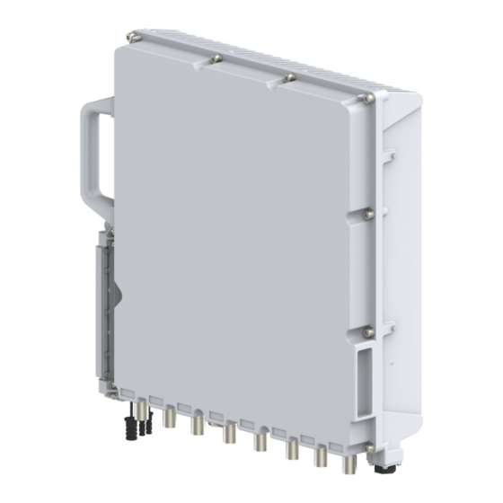
ZXSDR R8978 User Manual 3.2 Composition Figure 3-2 shows the composition of the ZXSDR R8978. Figure 3-2 Product Composition 1. Radiating pin 4. Operation and maintenance 7. Grounding bolt 2. Handle cavity 8. Breathable valve 3. LED indicators 5. Antenna interface 9. -
Page 19: Led Indicators
Chapter 3 Product Composition Note: The LMT/TST interface is used for ZTE maintenance personnel to perform commissioning and maintenance. 3.3 LED Indicators An indicator indicates the operating status of a device. Figure 3-3 shows the positions of the indicators. Figure 3-3 LED Indicators Table 3-2 describes the LED indicators. -
Page 20: Table 3-2 Indicator Descriptions
Flashing fast (ON for 70 ms and OFF for 70 ms): The system is powered. The software system has been started. The link between the ZXSDR R8978 and is not established. Alarm indicator OFF: There is no alarm. -
Page 21: Physical Interfaces And Cables
Figure 3-4 Protective Grounding Cable Connection End A is connected to the grounding interface of the ZXSDR R8978. End B is connected to the external grounding bar. Note: The connection area of the grounding bolt and OT terminal shall not be less than the area of the OT terminal, and the connection resistance must be less than 50 mΩ. -
Page 22: Dc Power Input Cable
The DC power input cable leads the external DC power into the operation and maintenance cavity of the ZXSDR R8978. It connects to the DC power through a dual-core DC bracket and a dual-core DC connector, to provide -48 V DC power input for the RRU. -
Page 23: Figure 3-6 Dc Power Input Cable
DC power cable through a junction box before connecting to the ZXSDR R8978. The ZXSDR R8978 does not have an AC power interface. The AC power should be converted into DC power through the outdoor AC power lightening protection box and then connected to the ZXSDR R8978. - Page 24 If... Then... Use the DC power supply If voltage drop occurs due to the distance between the ZXSDR R8978 with a junction box and the indoor DC power lighting protection box, a power cable with a larger diameter size is needed to reduce the voltage drop caused by long distance transmission.
-
Page 25: Lmt/Tst Interface Cable
Function The LMT/TST interface is located in the operation and maintenance cavity. It uses an RJ45 socket. interface is used for the interaction between the LMT and ZXSDR R8978 through an Ethernet port using TCP/IP. TELNET command lines are supported. -
Page 26: Optical Fiber
3.4.4 Optical Fiber Function The ZXSDR R8978 has two optical interfaces, OPT1 and OPT2. They are located in the operation and maintenance cavity. LC-type optical fiber connectors are supported. In the ZXSDR R8978 system, the optical interfaces have the following functions:... -
Page 27: Antenna Feeder Interface Cable
Figure 3-9 shows the external view. Figure 3-9 Optical Fiber Connection End A is connected to the optical ports (OPT1 and OPT2) of the ZXSDR R8978. End B is connected to the BBU/dowstream RRU/upstream RRU. Figure 3-10 illustrates the cable connection. -
Page 28: Figure 3-11 Antenna Feeder Interface Cable
Figure 3-11 Antenna Feeder Interface Cable Connection End A is connected to the interface of the ZXSDR R8978. End B is connected to the corresponding interface of the main antenna feeder. The antenna feeder interface cable is a 1/2 inch jumper. -
Page 29: Cal/Aisg Interface Cable
Figure 3-13 shows the external view. Figure 3-13 CAL Interface Cable Connection End A is connected to the CAL interface of the ZXSDR R8978. End B is connected to the CAL interface of the antenna. Figure 3-14 illustrates the cable connection. -
Page 30: Eam/Rgps Interface Cable
Because digital signal transmission is not affected by RF signal attenuation, the remote distance is long and good reliability and maintainability is ensured. Connection End A is connected to the EAM interface of the ZXSDR R8978. End B is connected to the dry contact output/RGPS interface of the external device. -
Page 31: Software Composition
Chapter 3 Product Composition Figure 3-15 External Cable Connection 3.6 Software Composition The ZXSDR R8978 software system is composed of: management Includes RF main control and RF channel management. adaptation software Provides an adaptation interface for entire operation and maintenance. -
Page 32: Figure 3-16 Software Composition
ZXSDR R8978 User Manual Uses a unified architecture design and provides a unified interface for the upper layer. Uses the Linux system independently developed by ZTE. Figure 3-16 shows the software composition of the ZXSDR R8978. Figure 3-16 Software Composition 3-16 SJ-20140808143736-001|2014-10-30 (R1.1) -
Page 33: Chapter 4 Operation And Maintenance
Technical Support.......................4-1 Fault Location......................4-2 Equipment Maintenance.....................4-3 Power On ........................4-4 Power Off ........................4-5 Parts Replacement.....................4-6 4.1 Technical Support ZTE technical support contract information is pasted in a conspicuous position in the equipment room, see Figure 4-1. SJ-20140808143736-001|2014-10-30 (R1.1) ZTE Proprietary and Confidential... -
Page 34: Fault Location
ZXSDR R8978 User Manual Figure 4-1 ZTE Technical Support Contact Information 4.2 Fault Location For the fault location methods in routine maintenance, refer to Table 4-1. Table 4-1 Fault Location Methods Maintenance Method Description Checking Alarms and This is the most common method for troubleshooting. By checking the... -
Page 35: Equipment Maintenance
In actual operation, all the methods can be used for troubleshooting. You can handle different faults based on the fault location methods and past experience. 4.3 Equipment Maintenance For a description of the ZXSDR R8978 equipment maintenance, refer to Table 4-2. Table 4-2 Equipment Maintenance... -
Page 36: Power On
Figure 4-2 shows the power-on flow. Figure 4-2 Power-on Flow For a description of the ZXSDR R8978 power-on flow, refer to Table 4-3. SJ-20140808143736-001|2014-10-30 (R1.1) ZTE Proprietary and Confidential... -
Page 37: Power Off
AC power 1. Turn on the switch of the AC power distribution unit of the ZXSDR R8978, and supply check whether the equipment output voltage is in the normal range. 2. Check whether the indicator or the indicator is normal. -
Page 38: Parts Replacement
Steps 1. Power off the ZXSDR R8978. 2. Open the cover of the ZXSDR R8978 maintenance cavity by using the M5 screw driver. 3. Paste a label at each end of every optical fiber. 4. Remove the fix screws from the cable crimper by using the M5 screwdriver. -
Page 39: Replacing The Optical Module
10. Tighten the jacking screw clockwise and jack the ZXSDR R8978 chassis. Then, loosen the plate-pressing bolt anti-clockwise. 11. Pull up the ZXSDR R8978 from the pole or wall-mounting bracket, and remove the ZXSDR R8978. 12. Put the faulty equipment into the moisture proof antistatic bag. Label the equipment model, sector ID and fault information on the bag. -
Page 40: Replacing The Rf Cable
The RF cable transmits or receives RF signals. Locate the faults through observation and analysis, and ensure that whether to replace the RF cable. Replacing the RF cable will interrupt all the services carried by the ZXSDR R8978. Prerequisite Prepare a proper RF cable to be replaced. -
Page 41: Figure 4-3 Connecting The Rf Cable
Stores the faulty RF cable and carton Steps 1. Power off the ZXSDR R8978. 2. Remove the waterproof tape of the RF cable. 3. Loosen the connectors of the RF cables by using the wrench. 4. Put the faulty cable into the moisture proof antistatic bag. Label the cable model, sector ID and fault information on the bag. -
Page 42: Figure 4-4 Waterproof Treatment
ZXSDR R8978 User Manual Figure 4-4 Waterproof Treatment 7. Power on the ZXSDR R8978. 8. The ZXSDR R8978 performs the self-test process after it is powered on. During the self-test, you need to observe the indicator status and perform operations accordingly. 4-10 SJ-20140808143736-001|2014-10-30 (R1.1) - Page 43 The self-test and replacement are successful. means that services are restored. The indicator is abnormal, which Troubleshoot the fault and handle the relevant alarms, or means that services are not contact ZTE technical support. restored. – End of Steps – 4-11 SJ-20140808143736-001|2014-10-30 (R1.1)
- Page 44 ZXSDR R8978 User Manual This page intentionally left blank. 4-12 SJ-20140808143736-001|2014-10-30 (R1.1) ZTE Proprietary and Confidential...
-
Page 45: Figure 5-1 Junction Box
Replacing the AC Power Lighting Protection Box ............5-6 5.1 Junction Box Function When the DC power supply is far from the ZXSDR R8978, to avoid voltage drop, a 2×10 DC power cable needs to be used. To connect to the 2×4 mm DC power cable used by the ZXSDR R8978, the 2×10 mm... -
Page 46: Figure 5-2 Junction Box Installation
ZXSDR R8978 User Manual Specifications Table 5-1 shows the specifications of the junction box. Table 5-1 Junction Box Specifications Name Specification Height × Width × Depth 233 mm × 119 mm × 55 mm (excluding the handle and waterproof cap) -
Page 47: Chapter 5 Accessory Devices
5.2 AC Power Lightening Protection Box Function The outdoor AC power lightening protection box is PPC33 A009. It protects the AC current from lightening and coverts AC into the DC that is applicable for the ZXSDR R8978. External View Figure 5-4 shows the external view of the AC power lightening protection box. -
Page 48: Figure 5-4 External View
ZXSDR R8978 User Manual Figure 5-4 External View Specifications Table 5-2 shows the specifications of the AC power lightening protection box. Table 5-2 Specifications of the AC Power Lightening Protection Box Item Specification Height × Width × Depth 300 mm × 250 mm × 118 mm (excluding the... -
Page 49: Figure 5-5 Installation Modes
Open the AC power lightening protection box and connect the internal and external cables, Figure 5-6. Figure 5-6 Interfaces and Cable Connection Name Description -220 AC_L 220 V AC live line -220 AC_N 220 V AV neutral line SJ-20140808143736-001|2014-10-30 (R1.1) ZTE Proprietary and Confidential... -
Page 50: Replacing The Ac Power Lighting Protection Box
Stores the faulty AC power lighting protection box and carton Steps 1. Power off the ZXSDR R8978. 2. Remove the waterproof tape from the cables. Uninstall the cables of the AC power lighting protection box by using the M6 screwdriver 3. - Page 51 5. Reinstall the proper AC power lighting protection box, fasten the anti-theft screws, and install the mounting plate and cables. Wrap the cables with the water proof tape. 6. Power on the ZXSDR R8978. – End of Steps – SJ-20140808143736-001|2014-10-30 (R1.1)
- Page 52 ZXSDR R8978 User Manual This page intentionally left blank. SJ-20140808143736-001|2014-10-30 (R1.1) ZTE Proprietary and Confidential...
-
Page 53: Chapter 6 Technical Specifications
Reliability Indexes ......................6-2 Grounding Requirement .....................6-3 Lightening and Surge Protection ................6-3 6.1 Physical Specifications Table 6-1 shows the physical specifications of the ZXSDR R8978. Table 6-1 Physical Specifications Item Specification Dimensions (H × W × D) 430 mm × 400 mm × 128 mm... -
Page 54: Power Consumption
Table 6-3 Power Consumption Specifications Item Power Consumption DL: UL=2:2 400 W DL: UL=3:1 580 W 6.4 Reliability Indexes For a description of the reliability indexes of the ZXSDR R8978, refer to Table 6-4. Table 6-4 Reliability Indexes Item Index Protection level IP66... -
Page 55: Grounding Requirement
6.5 Grounding Requirement In practical applications, the grounding resistance must be less than 10 Ω. 6.6 Lightening and Surge Protection Table 6-5 shows the lightening protection specification of the ZXSDR R8978. Table 6-5 Lightening Protection Specification Item Current Lightening protection specification 20 kA SJ-20140808143736-001|2014-10-30 (R1.1) - Page 56 ZXSDR R8978 User Manual This page intentionally left blank. SJ-20140808143736-001|2014-10-30 (R1.1) ZTE Proprietary and Confidential...
-
Page 57: Chapter 7 Environment Requirements
Power Supply Requirements ..................7-1 Operating Environment....................7-1 Storage Environment....................7-2 7.1 Power Supply Requirements Table 7-1 shows the requirements for the power supply of the ZXSDR R8978. Table 7-1 Power Requirements Item Requirement DC power supply -48 V DC (fluctuation range: -57 V DC to –37 V DC) The DC power supply must support the anti-reverse connection and over-current protection functions. -
Page 58: Storage Environment
Chemical Substance Environment Condition Item Description Salt fog Allowed 7.3 Storage Environment To ensure normal operation after installation, the ZXSDR R8978 should be stored in a package in a place with good protection. Climatic Environment Condition Item Description Lowed temperature -55 ℃... - Page 59 Allowed Biologic Environment Condition Item Description Plants Mold and fungus are allowed. Animals Rodents and other animals that damage the product are allowed, except termites Chemical Substance Environment Condition Item Description Salt fog Allowed SJ-20140808143736-001|2014-10-30 (R1.1) ZTE Proprietary and Confidential...
- Page 60 ZXSDR R8978 User Manual This page intentionally left blank. SJ-20140808143736-001|2014-10-30 (R1.1) ZTE Proprietary and Confidential...
-
Page 61: Figures
Figure 3-14 Connection of the CAL Interface Cable ..........3-14 Figure 3-15 External Cable Connection ..............3-15 Figure 3-16 Software Composition ................3-16 Figure 4-1 ZTE Technical Support Contact Information ..........4-2 Figure 4-2 Power-on Flow..................4-4 Figure 4-3 Connecting the RF cable................4-9 Figure 4-4 Waterproof Treatment ................ - Page 62 Figures This page intentionally left blank. SJ-20140808143736-001|2014-10-30 (R1.1) ZTE Proprietary and Confidential...
-
Page 63: Tables
Table 2-1 Key Features of the ZXSDR R8978 S2300..........2-3 Table 2-2 Key Features of the ZXSDR R8978 S2600..........2-4 Table 2-3 Key Features of the ZXSDR R8978 S2600M ..........2-4 Table 2-4 External Interface Description..............2-5 Table 3-1 Subsystem Description................3-1 Table 3-2 Indicator Descriptions ................ - Page 64 Tables This page intentionally left blank. SJ-20140808143736-001|2014-10-30 (R1.1) ZTE Proprietary and Confidential...
-
Page 65: Glossary
- Electro-Absorption Modulation - Global Positioning System - Internet Protocol - Local Maintenance Terminal - Long Term Evolution MIMO - Multiple-Input Multiple-Output MTBF - Mean Time Between Failures MTTR - Mean Time To Recovery SJ-20140808143736-001|2014-10-30 (R1.1) ZTE Proprietary and Confidential... - Page 66 ZXSDR R8978 User Manual - Operation, Administration and Maintenance - Operating System - Operation Support Subsystem - Radio Frequency RGPS - Remote GPS - Remote Radio Unit - Software Defined Radio - Transmission Control Protocol - Time Division TELNET - Telecommunication Network Protocol...
Need help?
Do you have a question about the ZXSDR R8978 and is the answer not in the manual?
Questions and answers