Table of Contents
Advertisement
Quick Links
Advertisement
Table of Contents

Related Manuals for Zte ZXSDR R8881 S4200


Summary of Contents for Zte ZXSDR R8881 S4200
- Page 1 ZXSDR R8881 S4200 Quick Installation Guide_R4.0_EN ...
-
Page 2: Table Of Contents
Contents ZXSDR R8881 S4200 Quick Installation Guide_R4.0_EN .............. 1 1 Overview ............................ 3 1.1 Physical Specifications ...................... 3 1.2 Space Requirements ...................... 4 1.2.1Recommended Installation Space ................ 4 1.2.2 Minimum Installation Space.................. 5 1.3 Mounting Manners ...................... 6 2 Installation Tools .......................... 7 3 ZXSDR R8881 S4200 Installing ...................... 9 3.1 Wall‐mounting ........................ 9 3.2 Installing 1‐2 ZXSDR R8881 S4200 on the pole .............. ... -
Page 3: 1 Overview
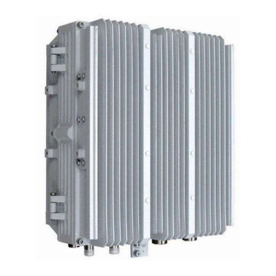
1 Overview 1.1 Physical Specifications Item Specifications Dimensions (Height * Width * Depth) 215 mm (D) x 320 mm (W) x 370 mm (H) Weight 18 kg DC: -48 V (-62 V – -37 V) Rated Input Voltage Operating Temperature -30℃... -
Page 4: Space Requirements
1.2 Space Requirements 1.2.1Recommended Installation Space ... -
Page 5: Minimum Installation Space
1.2.2 Minimum Installation Space ... -
Page 6: Mounting Manners
1.3 Mounting Manners Wall-mounting... -
Page 7: 2 Installation Tools
Pole-mounting 2 Installation Tools Electrical punch drill Earth resistance tester Vacuum cleaner Multimeter Coaxial cable stripper Power Strip... - Page 8 Screwdriver Hex key wrench Hydraulic Crimper Wrench Cutter Claw hammer Pliers Steel tape Spirit Level Crimper Safety helmet Slip-proof glove Hacksaw Ladder ...
-
Page 9: 3 Zxsdr R8881 S4200 Installing
3 ZXSDR R8881 S4200 Installing 3.1 Wallmounting In most cases, two expansion bolts are enough to fasten the mounting bracket, which should pass through the upper two screw holes on the face of the bracket. However, if the ZXSDR R8881 S4200 is installed along a high-speed railway, in a tunnel or an earthquake-prone zone, four expansion bolts are required. - Page 10 RRU support on the back of a ZXSDR R8881 S4200. 5. Fit the hangers of the RRU 6. Reinstall the screw that is removed support into the grooves of in Step 4 and tighten it to fasten the the mounting bracket.
-
Page 11: Installing 1-2 Zxsdr R8881 S4200 On The Pole
3.2 Installing 12 ZXSDR R8881 S4200 on the pole Note: 1. The diameter of the pole ranges from 60mm to 120 mm. If the diameter is no more than 90 mm, a pad (as shown in the left figure) should be used in tightening bolt;otherwise, the pad is not necessary. - Page 12 2. Place the two mounting brackets on a pole in a back-to-back manner and put the fixed bolts into the bolt grooves on the opposite brackets. Pole Diameter > 90 mm Pole Diameter ≤ 90 mm ...
- Page 13 3. Tighten the bolts to fix the mounting brackets on the pole. 4. Remove the screw in the middle of each mounting bracket.
- Page 14 5. Fit the hangers of the RRU support into the grooves of the mounting bracket. 6. Reinstall the screw that is removed in Step 4 and tighten it to fasten the RRU. 7. This installation method is applicable to the installation of one or two ZXSDR R8881 S4200s.
-
Page 15: Installing The Odcpd1
3.3 Installing the ODCPD1 When a 16mm power cable is used, the ODCPD1 is required. ... - Page 16 1. Use four screws to fasten a mounting frame in the front of the device. ...
- Page 17 2. Use two screws to fasten the ODCPD1 on the mounting frame. 3. If two devices are installed in parallel, the ODCPD1s should be installed in this way: one is in the front and the other is at the back of devices respectively.
-
Page 18: Cable Connection
4 Cable Connection 4.1 ZXSDR R8881 S4200 Ports ... - Page 19 Label Interface Connector Type Purpose 2-pin round connector Provides -48 V DC power -48V DC Power Input Port (male) supply Used to monitor the dry 8-pin round connector Monitoring Port contact (male) devices Provides AISG connection 8-pin square connector AISG AISG Device Port for an (female)
-
Page 20: Overview
DC output port of the power supply ZXSDR R8881 S4200 device PWR port IMPORTANCE: The power port of a DC-type ZXSDR R8881 S4200 is a two-core round connector (with pins). The DC power cable that is made at the site for the DC-type ZXSDR R8881 S4200... -
Page 21: Connecting The Grounding Wire
3. If the ODCPD1 is used, use one grounding wire to connect the GND port of ZXSDR R8881 S4200 to the grounding point of the ODCPD1, and then use another grounding wire to connect the grounding point of the ODCPD1/PIMAC to the... -
Page 22: Connecting The Rf Jumpers
4.2.3 Connecting the RF jumpers Connect two feeders to the ANT1 and ANT2 ports of the ZXSDR R8881 S4200 respectively. -
Page 23: Connecting The Optical Fiber
4.2.4 Connecting the Optical Fiber 1. Remove the protection cap from the optical fiber. Then, detach the outer protection cover. 2. Remove two white covers. 3. -
Page 24: Connecting The Aisg Cable
OPT1 port of ZXSDR the OPT2 port of the upper-level ZXSDR R8881 S4200 and R8881 S4200. the OPT1 port of the lower-level ZXSDR R8881 S4200. 4.2.5 Connecting the AISG Cable Connect the AISG cable to the AISG port of the ZXSDR R8881 S4200. ... -
Page 25: Connecting The Mon Cable
Connect the MON cable to the MON port of the ZXSDR R8881 S4200. 4.2.7 Connecting the Frequency Spreading Cable In the case of frequency spreading, use a frequency spreading cable to connect the RXout port of the local R8881 to the RXin port of the remote ZXSDR R8881 S4200. ... -
Page 26: Making And Installing A Power Cable
4.2.8 Making and Installing a Power Cable 1. Remove the bottom cover and the shell from a power connector. 2. Let a power cable pass through the bottom cover and the shell. Note: If the 2x10 mm cable is used, the rubber ring inside the connector shell should be removed. - Page 27 5. Insert the positive and negative wires to the 4. Follow the instructions on the correct holes of the power connector (The blue wire connector drawing to process the is negative and the black wire is positive). cable. 6. Insert the shielding wire of the cable to the shielding wire hole.
- Page 28 9. Use a wrench to hold the connector 10. Use a wrench to hold the connector shell, and protection cover, and another to tighten another to tighten the bottom cover. The torque to the shell. The torque to tighten the tighten the cover should not be less than 1.2 N·m.
-
Page 29: Connecting Cables Of Odcpd1
4.2.9 Connecting Cables of ODCPD1 1. Use a grounding wire to connect the grounding terminal of the ODCPD1 and the 2. Screw off the six screws on the cover nearest outdoor grounding busbar. of ODCPD1 to remove the cover. Note: You can use any one of the two grounding terminals of ODCPD1. - Page 30 3. Process the 16mm2 power cable and ZXSDR R8881 S4200 power cable according to the drawings inside the ODCPD1 cover. 4. Crimp four lugs onto the ends of power wires. 5. Fix the power cables with the clamps on the ODCPD1.The 16mm2 power cable should be on the right, and the ZXSDR R8881 S4200 power cable on the left.
-
Page 31: Selecting Positions For Grounding Clips
4.3 Selecting Positions for Grounding Clips 4.3.1 Grounding Clips for Antenna Feeders 1. When the RRU is installed close to the antenna, 1.1 Grounding is not required if the feeder or jumper is less than 5 m. 1.2 You should ground the feeder on the RRU side if the feeder is greater than 5 m but less than 20 m. -
Page 32: Grounding Clips For Power Cables
3.1 You should ground the feeder at the very position before it goes through the feeder window of the equipment room. 3.2 You should ground the feeder on the antenna side. 3.3 If the feeder is laid on an iron tower, you should ground the feeder before it leaves the tower. -
Page 33: 5 Installation Check
5 Installation Check Checking Items Result The protection grounding wires of the equipment are properly Pass installed to the nearest copper grounding busbar. □ Fail Before connecting protection grounding wires, rust or dust Pass should be removed from the surface of the grounding terminal to □... - Page 34 Antenna kit/Cable Specifications Item Description Specification Frequency band range 410-425 MHz -MHz 1/2、7/8 feeder Joint Model SL16 or uesr Specified Antenna Type/ Pattern: Omnidirectional antenna Antenna's Gain 7.8 dBi Cable Specifications Feeder 1/2、7/8 feeder Environmental Specifications IP level The protection level is IP65. Grounding Requirements CBN ground resistance: ≤...
- Page 35 FCC Radiation Exposure Statement: Any Changes or modifications not expressly approved by the party responsible for compliance could void the user's authority to operate the equipment. This device complies with part 15 of the FCC Rules. Operation is subject to the following two conditions: (1) This device may not cause harmful interference, and (2) this device must accept any interference received, including interference that may cause undesired operation.
Need help?
Do you have a question about the ZXSDR R8881 S4200 and is the answer not in the manual?
Questions and answers