Table of Contents
Advertisement
Quick Links
Advertisement
Table of Contents

Related Manuals for Zte ZXSDR BS8908 G060


Summary of Contents for Zte ZXSDR BS8908 G060
- Page 1 ZXSDR BS8908 G060 Outdoor GSM Mode Micro BTS User Manual V1.00 ZTE CORPORATION NO. 55, Hi-tech Road South, ShenZhen, P.R.China Postcode: 518057 Tel: +86-755-26771900 Fax: +86-755-26770801 URL: http://ensupport.zte.com.cn E-mail: support@zte.com.cn...
- Page 2 ZTE CORPORATION is prohibited. Additionally, the contents of this document are protected by contractual confidentiality obligations. All company, brand and product names are trade or service marks, or registered trade or service marks, of ZTE CORPORATION or of their respective owners.
-
Page 3: Table Of Contents
Contents Chapter 1 System Overview ..............1-1 1.1 System Background ................... 1-1 1.2 System Position ....................1-1 1.2.1 System Position in Network............... 1-1 1.2.2 System Position in Distributed Base Station ..........1-3 1.3 Cabinet Appearance................... 1-4 1.4 Product Features....................1-5 1.5 Services and Functions .................. - Page 4 5.1.2 Safety Symbols ..................5-1 5.1.3 Safety Instructions Guideline..............5-3 5.2 Installation Preparations ..................5-5 5.2.1 Installation Environment Check ..............5-5 5.2.2 Personnel ....................5-6 5.2.3 Tools and Instruments Preparation ............5-6 5.3 Unpacking and Inspection................... 5-8 5.3.1 Packing Box of BS8908 ................5-8 5.3.2 Unpacking and Inspection Flow..............
- Page 5 Glossary ......................V...
-
Page 7: Chapter 1 System Overview
ZTE Corporation has launched various series of base stations to satisfy operators' demands. Of the ZTE base station solutions, one is to divide the base station into two units: Base Band Unit (BBU) and Remote Radio Unit (RRU). BS8908 is a base station with BBU and RRU being integrated. -
Page 8: Figure 1-1 Bs8908 Position In Gsm Network
ZXSDR BS8908 G060 User Manual Figure 1-1 BS8908 Position in GSM Network BTS is responsible for providing the wireless coverage for the GSM network. It performs the following functions: Makes MS access the network and implements the radio link transmission function through Um interface. -
Page 9: System Position In Distributed Base Station
The BBU+RRU mode reduces the equipment room requirement, decreases the feeder loss, and provides a more flexible site layout mode. BBU is arranged indoors, connecting RRU, which is often outdoors, through optical fiber. Figure 1-3 shows the distributed base station architecture. SJ-20101104174421-001|20110425(R1.1) ZTE Proprietary and Confidential... -
Page 10: Cabinet Appearance
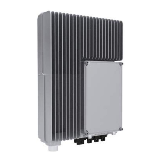
ZXSDR BS8908 G060 User Manual Figure 1-3 Distributed Base Station System Structure 1.3 Cabinet Appearance Figure 1-4 shows the BS8908 cabinet appearance. Figure 1-4 Cabinet Appearance SJ-20101104174421-001|20110425(R1.1) ZTE Proprietary and Confidential... -
Page 11: Product Features
CS 64 Kbps data service domain service: UL/DL 64 Kbps, UL/DL 128 Kbps, and UL/DL 384 Kbps data service Concurrent service: CS-domain (AMR 12.2 Kbps, CS 64 Kbps) + PS-domain (64 Kbps, 128 Kbps, 384 Kbps) SJ-20101104174421-001|20110425(R1.1) ZTE Proprietary and Confidential... -
Page 12: Operation And Maintenance
ZXSDR BS8908 G060 User Manual Basic Functions BS8908 supports the following functions. 1. With Um interface, BS8908 accomplishes terminal access and RF link transmission, including: RF signal processing, channel coding and decoding, channel multiplexing and de-multiplexing, measurement and reporting, power control, transmission diversity, receiving diversity, calibration, and synchronization. -
Page 13: Figure 1-5 Bs8908 Operation And Maintenance
Chapter 1 System Overview Figure 1-5 BS8908 Operation and Maintenance SJ-20101104174421-001|20110425(R1.1) ZTE Proprietary and Confidential... - Page 14 ZXSDR BS8908 G060 User Manual This page intentionally left blank. SJ-20101104174421-001|20110425(R1.1) ZTE Proprietary and Confidential...
-
Page 15: Chapter 2 System Indices
110 V/220 V (90 V AC ~ 290 V AC) Environment Condition Item Index Working environment temperature -40 °C ~ 55 °C Relative working environment humidity 5% ~ 100% Protection class IP65 Grounding resistance ≤ 5 Ω Reliability Item Index Availability 99.999576% SJ-20101104174421-001|20110425(R1.1) ZTE Proprietary and Confidential... -
Page 16: Radio Performance Indices
ZXSDR BS8908 G060 User Manual Item Index MTBF ≥ 236,000 hours MTTR 1 hour The system's entire service interruption time ≤ 2.227 System service interruption time minute/year 2.2 Radio Performance Indices The following lists radio performance indices. Capacity Indices Item... - Page 17 GPS interface One, receiving the GPS signal. One, Abis interface 75 Ω E1, Abis interface 120 Ω E1 or 100 Ω Abis E1 interface Abis GE interface One, Abis Ethernet optical interface or electrical interface. SJ-20101104174421-001|20110425(R1.1) ZTE Proprietary and Confidential...
- Page 18 ZXSDR BS8908 G060 User Manual This page intentionally left blank. SJ-20101104174421-001|20110425(R1.1) ZTE Proprietary and Confidential...
-
Page 19: Chapter 3 System Structure And Principles
Table 3-1 External Interfaces Connected External Label Interface Functions System GPS antenna Receives the GPS antenna signal Performs additional functions such as down- USB interface loading version ABIS1 IBSC IP Abis interface SJ-20101104174421-001|20110425(R1.1) ZTE Proprietary and Confidential... -
Page 20: Equipment Indicators
ZXSDR BS8908 G060 User Manual Connected External Label Interface Functions System Provides RS485 communication interface for External auxiliary and moni- the peripheral and provides the dry contact toring equipments input E1/T1 iBSC Four pairs of E1/T1 Abis interfaces AISG electrical antenna and... -
Page 21: Table 3-2 Indicators And Buttons
2nd E1 is normal; OFF: the 2nd E1 is unavailable Flashing at 8 Hz in the seventh second and flashing four times: the 3rd E1 is normal; OFF: the 3rd E1 is unavailable Alarm indicator OFF: normal ON: alarm SJ-20101104174421-001|20110425(R1.1) ZTE Proprietary and Confidential... -
Page 22: Hardware Subsystem
ZXSDR BS8908 G060 User Manual 3.2 Hardware Subsystem 3.2.1 Hardware Architecture Figure 3-3 shows the hardware architecture of the system. Figure 3-3 BS8908 Hardware System BS8908 consists of TRB, MCD, SICB, BIPB, BDCP/BACP, and the structure subsystem, as shown in Table 3-3. -
Page 23: Module Functions
Providing the channel from the two-channel antenna to TRB's receiving-band channel In the channel, suppressing interference and spurious radiation out of the working frequency band Implementing diversity reception SICB Performs signal conversion between TRB and BIPB BIPB Signal accessing Lightning protection processing Crosstalk protection SJ-20101104174421-001|20110425(R1.1) ZTE Proprietary and Confidential... -
Page 24: Software Subsystem
ZXSDR BS8908 G060 User Manual Outputting AISG interface signal after lightning protection being performed Panel interfaces BDCP/BACP AC power supply voltage conversion DC power supply voltage conversion Normal protection for the power supply Voltage-adjustment for the power amplifier Structure Subsystem Provides the structure of modules 3.3 Software Subsystem... - Page 25 1. Operation and Maintenance Subsystem (OMS) performs the operation and maintenance functions including configuration, alarm, and status control. 2. Baseband Unit Control software subsystem (DBB) performs the service signaling processing. 3. Digital Base Band software subsystem (BUC) performs the digital baseband processing. SJ-20101104174421-001|20110425(R1.1) ZTE Proprietary and Confidential...
- Page 26 ZXSDR BS8908 G060 User Manual This page intentionally left blank. SJ-20101104174421-001|20110425(R1.1) ZTE Proprietary and Confidential...
-
Page 27: Chapter 4 Networking And Configuration
Table of Contents Networking .........................4-1 Configuration......................4-2 4.1 Networking 4.1.1 Star Networking Figure 4-1 shows the star networking mode of BS8908. Figure 4-1 Star Networking 4.1.2 Cascading Networking Figure 4-2 shows the cascading networking mode of BS8908. SJ-20101104174421-001|20110425(R1.1) ZTE Proprietary and Confidential... -
Page 28: Configuration
ZXSDR BS8908 G060 User Manual Figure 4-2 Cascading Networking 4.2 Configuration 4.2.1 Configuration Principles A single cabinet supports the configuration of 1 ~ 6 TRXs. To guarantee the output power, the configuration of over 4 TRXs is implemented in multi-cabinet structure. -
Page 29: Figure 4-4 O5 ~ O8 Configuration
The hardware configuration is the same as that of O5 ~ O8 configuration, but the frequency configuration of the primary cabinet and the secondary cabinet must be the same. RRU Function Configuration BS8908 can also work as an RRU, connecting BBU. SJ-20101104174421-001|20110425(R1.1) ZTE Proprietary and Confidential... -
Page 30: Figure 4-6 Rru Function Configuration Diagram
ZXSDR BS8908 G060 User Manual Figure 4-6 RRU Function Configuration Diagram BBU Function Configuration BS8908 can also work as a BBU, connecting RRU. Figure 4-7 BBU Function Configuration Diagram SJ-20101104174421-001|20110425(R1.1) ZTE Proprietary and Confidential... -
Page 31: Chapter 5 Installation
The safe instructions given in this manual are supplementary to the local safety regulations. ZTE shall not bear any liabilities incurred by violation of universal safety operation requirements, or violation of safety standards for designing, manufacturing and equipment usage. - Page 32 ZXSDR BS8908 G060 User Manual Safety Symbol Meaning Electrostatic: Device may be sensitive to static electricity. Electric shock: There is a risk of electric shock. High temperature: Surface is hot and may cause personal injury if touched. Laser: Beware of strong laser beam.
-
Page 33: Safety Instructions Guideline
In a dry environment, the static voltage carried by human body can be up to 30 kV and can remain in human body for a long time. Person carrying static charge can damage a component by touching it and hence transferring the charge to the component. SJ-20101104174421-001|20110425(R1.1) ZTE Proprietary and Confidential... - Page 34 ZXSDR BS8908 G060 User Manual To prevent human body's static charge from damaging sensitive components, wear the antistatic wrist strap and ground its other end before touching the equipment or holding a plug-in board, circuit board, or IC chip etc.
-
Page 35: Installation Preparations
Replacing any part or altering the equipment might result in unexpected dangers. Therefore, do not replace any part or alter the equipment unless being authorized. To ensure your safety, contact ZTE in case of any queries. 5.2 Installation Preparations 5.2.1 Installation Environment Check Before installation, check the installation environment according to requirements specified in the Environment Acceptance Report. -
Page 36: Personnel
The installation personnel perform the installation. Requirements on the installation supervisor: Being aware of the importance of quality. Having participated in relevant training held by ZTE Corporation and being qualified for installation supervision. Being familiar with material, tools, and operations involved in the installation. -
Page 37: Table 5-3 Tools And Instruments
Chapter 5 Installation Table 5-3 Tools and Instruments Name Example Name Example Coax- cable stripper Screwdriver Electric percus- sive drill Hex wrench Safety hel- Plier Horizontal Spanner ruler Paper knife Ladder Grounding resistance tester Multimeter SJ-20101104174421-001|20110425(R1.1) ZTE Proprietary and Confidential... -
Page 38: Unpacking And Inspection
ZXSDR BS8908 G060 User Manual Name Example Name Example Multi- functional press plier Dust collector Slip-proof Claw ham- gloves Hydraulic Hacksaw crimper Connector Tape mea- sure (5m) 5.3 Unpacking and Inspection 5.3.1 Packing Box of BS8908 BS8908 is packed in carton. The BS8908 cabinet is wrapped in EPE foam pad and put in... -
Page 39: Unpacking And Inspection Flow
Figure 5-1 Package of BS8908 5.3.2 Unpacking and Inspection Flow Figure 5-2 shows the flow of unpacking and inspection. For operations details and precautions, refer to the engineering document of BS8908 Unpacking and Inspection Guide. SJ-20101104174421-001|20110425(R1.1) ZTE Proprietary and Confidential... -
Page 40: Installation Overview
ZXSDR BS8908 G060 User Manual Figure 5-2 Unpacking and Inspection Flow 5.4 Installation Overview 5.4.1 Installation Flow Figure 5-3 shows the installation flow. 5-10 SJ-20101104174421-001|20110425(R1.1) ZTE Proprietary and Confidential... -
Page 41: Hoisting Operation Precautions
Do not use the steel wire rope as the hoisting rope. To avoid accidents, make sure that there is no personnel left around the tower (especially under the RRU). 5-11 SJ-20101104174421-001|20110425(R1.1) ZTE Proprietary and Confidential... -
Page 42: Installation Modes And Installation Accessories
ZXSDR BS8908 G060 User Manual 5.5 Installation Modes and Installation Accessories 5.5.1 Installing Accessories Table 5-4 lists the installation accessories of BS8908 and the corresponding functions. Table 5-4 BS8908 Installation Accessories and Functions Name Appearance Functions Wall-mounted Used in wall-mounted... -
Page 43: Wall-Mounted Installation Mode
5.5.2 Wall-Mounted Installation Mode In this installation mode, after the wall-mounted installation component is fixed on the wall, BS8908 is fixed on the wall-mounted installation component through screws, as shown in Figure 5-4. 5-13 SJ-20101104174421-001|20110425(R1.1) ZTE Proprietary and Confidential... -
Page 44: Pole-Mounted Installation Mode
ZXSDR BS8908 G060 User Manual Figure 5-4 Wall-Mounted Installation of BS8908 5.5.3 Pole-Mounted Installation Mode Figure 5-5 shows the case when one BS8908 is installed on the pole. 5-14 SJ-20101104174421-001|20110425(R1.1) ZTE Proprietary and Confidential... -
Page 45: Figure 5-5 Installing One Bs8908 On Pole
In the case of installing one BS8908 on the pole, the pole's diameter must be within the range of 40 mm ~ 114 mm. The pole design complies with the GB/T8162 standard. Figure 5-6 shows the case when two BS8908s are installed on the pole. 5-15 SJ-20101104174421-001|20110425(R1.1) ZTE Proprietary and Confidential... -
Page 46: Figure 5-6 Installing Two Bs8908S On Pole
ZXSDR BS8908 G060 User Manual Figure 5-6 Installing Two BS8908s on Pole Note: In the case of installing two BS8908s on the pole, the pole's diameter must be within the range of 40 mm ~ 114 mm. The pole design complies with the GB/T8162 standard. -
Page 47: Slot Steel Installation Mode And Equilateral Angle Steel Installation Mode
5, 6.3, 6.5, 8, and 10). The slot steel type complies with the GB/T707 standard. In both the two installation modes, the pole-mounted installation component is fixed on the slot steel or the equilateral angle steel. For installation details, refer to that of the pole-mounted installation mode. 5-17 SJ-20101104174421-001|20110425(R1.1) ZTE Proprietary and Confidential... -
Page 48: R8860 Installation
ZXSDR BS8908 G060 User Manual 5.6 R8860 Installation 5.6.1 Installing BS8908 on the Wall Steps 1. According to the BS8908 installation position specified in the engineering design, drill holes on the wall and install the expansion bolts. The hole is 70 mm deep. -
Page 49: Figure 5-9 Installing Wall-Mounted Installation Component
3. Mount the BS8908 cabinet on the wall-mounted installation component and align it with the groove, as shown in Figure 5-10. Fix the cabinet on the wall-mounted installation component through four M6 burglarproof screws, as shown in Figure 5-11. Figure 5-10 Groove Schematic Diagram 5-19 SJ-20101104174421-001|20110425(R1.1) ZTE Proprietary and Confidential... -
Page 50: Pole-Mounted Installation (With Pole Fixing Plate)
ZXSDR BS8908 G060 User Manual Figure 5-11 Fixing Cabinet 1. Wall-mounted installation component 2. Screw – End of Steps – 5.6.2 Pole-Mounted Installation (with Pole Fixing Plate) 5.6.2.1 Installing One BS8908 Steps 1. Assemble the wall-mounted installation component and the pole fixing plate, as shown Figure 5-12. -
Page 51: Figure 5-12 Assembling Wall-Mounted+Pole-Mounted Component
3. Mount the BS8908 cabinet on the wall-mounted installation component and align it with the slot. Fix the cabinet on the wall-mounted installation component through four M6 burglarproof screws, as shown in Figure 5-14. 5-21 SJ-20101104174421-001|20110425(R1.1) ZTE Proprietary and Confidential... -
Page 52: Figure 5-14 Fixing Cabinet
ZXSDR BS8908 G060 User Manual Figure 5-14 Fixing Cabinet 1. Wall-mounted installation component 2. Burglarproof screw – End of Steps – 5.6.2.2 Installing Two BS8908s Steps 1. Assemble the pole fixing plate and the two wall-mounted installation components respectively, as shown in Figure 5-15. -
Page 53: Figure 5-16 Installing Wall-Mounted+Pole-Mounted Component
Fix the BS8908 cabinets on the wall-mounted installation components through eight M6 burglarproof screws, as shown in Figure 5-17. Figure 5-17 Fixing Cabinet 1. Wall-mounted installation component 2. Screw – End of Steps – 5-23 SJ-20101104174421-001|20110425(R1.1) ZTE Proprietary and Confidential... -
Page 54: Figure 5-18 Assembling Wall-Mounted+Pole-Mounted Component
ZXSDR BS8908 G060 User Manual 5.6.2.3 Installing Three BS8908s Steps 1. Assemble the pole fixing plate and the two wall-mounted installation components respectively, as shown in Figure 5-18. Figure 5-18 Assembling Wall-Mounted+Pole-Mounted Component 1. Bolt 4. Wall-mounted 6. Pole installation 2. -
Page 55: Installing Cable Rack
Figure 5-21 Fixing Cabinet 1. Screw – End of Steps – 5.6.3 Installing Cable Rack Prerequisites BS8908 is installed. Steps 1. Install the cable rack at the bottom of BS8908, as shown in Figure 5-22. 5-25 SJ-20101104174421-001|20110425(R1.1) ZTE Proprietary and Confidential... -
Page 56: Figure 5-22 Installing Cable Rack
ZXSDR BS8908 G060 User Manual Figure 5-22 Installing Cable Rack 1. Cable rack 2. Screw Figure 5-23 shows the installed cable rack. 5-26 SJ-20101104174421-001|20110425(R1.1) ZTE Proprietary and Confidential... -
Page 57: Installing Lightning Protection Box
The following takes installing one BS8908 on the pole for example to illustrate the installation procedure. Steps 1. Install the lightning-protection-box installation component on the side of the wall-mounted installation component, as shown in Figure 5-24. 5-27 SJ-20101104174421-001|20110425(R1.1) ZTE Proprietary and Confidential... -
Page 58: Figure 5-24 Installing Lightning-Protection-Box Installation Component
ZXSDR BS8908 G060 User Manual Figure 5-24 Installing Lightning-Protection-Box Installation Component 1. Wall-mounted 2. Lightning-protecti 3. Screw installation component on-box installation component 2. Install the lightning protection box on the lightning-protection-box installation component, as shown in Figure 5-25. 5-28 SJ-20101104174421-001|20110425(R1.1) -
Page 59: Figure 5-25 Installing Lightning Protection Box
Figure 5-25 Installing Lightning Protection Box 1. Wall-mounted 3. Lightning protection installation component 2. Lightning-protecti 4. Big washer on-box installation 5. Spring washer component 6. Screw Figure 5-26 shows the installed lightning protection box. 5-29 SJ-20101104174421-001|20110425(R1.1) ZTE Proprietary and Confidential... -
Page 60: External Cable Installation
ZXSDR BS8908 G060 User Manual Figure 5-26 Installed Lightning Protection Box – End of Steps – 5.7 External Cable Installation 5.7.1 External Cable Connections Table 5-5 shows the external cable connections of BS8908. Table 5-5 External Cable Connections of BS8908... - Page 61 One end of the cable is N-J connector, and interface cable BS8908 to the GPS antenna. the other end of the cable is SMA connector. The cable is the 50 Ω coaxial cable. 5-31 SJ-20101104174421-001|20110425(R1.1) ZTE Proprietary and Confidential...
-
Page 62: External Cable Installation Flow
ZXSDR BS8908 G060 User Manual Cable Connection Connector and Cable Description Antenna feeder Connecting BS8908 to the main The RF jumper is usually made of the 2 m jumper antenna feeder. 1/2" jumper. According to the actual condition, installation personnel can make the cable to... -
Page 63: Installing Power Cable
Figure 5-27 External Cable Installation Flow 5.7.3 Installing Power Cable Prerequisites Wear the antistatic wrist strap. Cut a certain length of power cable according to actual requirement. Make sure that the power supply branch output is disconnected. 5-33 SJ-20101104174421-001|20110425(R1.1) ZTE Proprietary and Confidential... -
Page 64: Figure 5-28 Dc Power Cable Structure
ZXSDR BS8908 G060 User Manual Caution! Check the cabinet's power supply status. Do not install the power cable when it is live, which, if not avoided, could result in death or serious injury. Context BS8908 provides two power supply modes according to actual engineering plan: DC power supply and AC power supply. -
Page 65: Installing Grounding Cable
The grounding system and connection points of indoor and outdoor copper grounding bars have been constructed completely. Context The grounding cable of BS8908 is made of the 25 mm yellow/green fire-resistant multi-strand wires. End A of the cable is in crimp connection with the double-hole 5-35 SJ-20101104174421-001|20110425(R1.1) ZTE Proprietary and Confidential... -
Page 66: Installing Abis E1 Cable
ZXSDR BS8908 G060 User Manual grounding terminal, and end B of the cable is the round metal bare terminal, which is called cabling lug or copper lug, as shown in Figure 5-30. Figure 5-30 Grounding Cable Structure Steps 1. Hang the copper lugs at end A of the grounding cable on the two grounding bolts of the BS8908 cabinet, and fix them. -
Page 67: Figure 5-32 E1 Cable
1. Bind the cable tie at the bottom of the cable rack corresponding to the E1 (E1/T1) interface. 2. Make the E1 cable pass through the cable tie, tighten it to the cable rack, and fasten the cable tie. 5-37 SJ-20101104174421-001|20110425(R1.1) ZTE Proprietary and Confidential... -
Page 68: Installing Abis Ethernet Cable
ZXSDR BS8908 G060 User Manual 3. Remove the protective cap of the E1 (E1/T1) interface, connect end A of the E1 cable to the E1 (E1/T1) interface, and fasten the screw at the interface. 4. For the E1 cable, connect end B to the cable trough according to Table 5-8. -
Page 69: Installing Fiber Connecting Rru
During the installation, hold the LC connector with hand. Do not hold the fiber lest the fiber might be broken. 5. Paste the direction labels at both ends of the fiber. – End of Steps – 5-39 SJ-20101104174421-001|20110425(R1.1) ZTE Proprietary and Confidential... -
Page 70: Installing Environment Monitoring Cable
ZXSDR BS8908 G060 User Manual 5.7.8 Installing Environment Monitoring Cable Prerequisites Wear the antistatic wrist strap. The BS8908 cabinet is installed and fixed. Context The environment monitoring cable is between the BS8908 system and the external environment monitoring system. It provides the connection between dry contact and RS485 monitoring signal. -
Page 71: Installing Aisg Control Cable
1. Bind the cable tie at the bottom of the cable rack corresponding to the AISG debugging interface. 2. Make the AISG control cable pass through the cable tie, tighten it to the cable rack, and fasten the cable tie. 5-41 SJ-20101104174421-001|20110425(R1.1) ZTE Proprietary and Confidential... -
Page 72: Installing Gps Cable
ZXSDR BS8908 G060 User Manual 3. Remove the protective cap of the AISG debugging interface, connect end A of the AISG control cable to the debugging interface (AISG) of BS8908, and fasten the screw at the interface. 4. Connect end B of the AISG control cable to the control interface of the electrical antenna. -
Page 73: Figure 5-37 Antenna Feeder Jumper Installation Position
2. Connect the DIN-type male connector of the antenna feeder jumper with the RF-antenna interface of the cabinet. 3. Perform waterproof handling for the antenna feeder, equipment interface, and interconnection connectors. – End of Steps – 5-43 SJ-20101104174421-001|20110425(R1.1) ZTE Proprietary and Confidential... - Page 74 ZXSDR BS8908 G060 User Manual This page intentionally left blank. 5-44 SJ-20101104174421-001|20110425(R1.1) ZTE Proprietary and Confidential...
-
Page 75: Figures
Figures Figure 1-1 BS8908 Position in GSM Network............1-2 Figure 1-2 Base Station (BBU+RRU) ................ 1-3 Figure 1-3 Distributed Base Station System Structure..........1-4 Figure 1-4 Cabinet Appearance ................1-4 Figure 1-5 BS8908 Operation and Maintenance ............1-7 Figure 3-1 External Interfaces at Cabinet Bottom ............3-1 Figure 3-2 BS8908 Indicators ................... - Page 76 ZXSDR BS8908 G060 User Manual Figure 5-17 Fixing Cabinet..................5-23 Figure 5-18 Assembling Wall-Mounted+Pole-Mounted Component......5-24 Figure 5-19 Installing Wall-Mounted+Pole-Mounted Component ......5-24 Figure 5-20 Installing the Third Wall-Mounted Installation Component ....5-25 Figure 5-21 Fixing Cabinet..................5-25 Figure 5-22 Installing Cable Rack ................5-26 Figure 5-23 Installed Cable Rack ................
- Page 77 Tables Table 3-1 External Interfaces ..................3-1 Table 3-2 Indicators and Buttons................3-3 Table 3-3 Cabinet Hardware Composition ..............3-4 Table 4-1 Typical System Configuration Specifications..........4-2 Table 5-1 Safety Symbols and Meanings ..............5-1 Table 5-2 Working Temperature and Humidity Requirement for BS8908 ....5-5 Table 5-3 Tools and Instruments ................
- Page 78 Tables This page intentionally left blank.
- Page 79 Glossary AISG - Antenna Interface Standards Group Abis - Abis Interface between BSC and BTS - Base Station Controller - Base Transceiver Station - Core Network - Circuit Service - Downlink - Digital Pre-Distortion EDGE - Enhanced Data rates for GSM Evolution - Frame Protocol GPRS - General Packet Radio Service...
- Page 80 ZXSDR BS8908 G060 User Manual - Printed Circuit Board - Packet Service - Radio Network Controller - Software Defined Radio - User Equipment - Uplink UMTS - Universal Mobile Telecommunication System...
Need help?
Do you have a question about the ZXSDR BS8908 G060 and is the answer not in the manual?
Questions and answers