Sign In
Upload
Manuals
Brands
ZTE Manuals
Accessories
ZXSDR BS8800 C200
ZTE ZXSDR BS8800 C200 Base Station Manuals
Manuals and User Guides for ZTE ZXSDR BS8800 C200 Base Station. We have
1
ZTE ZXSDR BS8800 C200 Base Station manual available for free PDF download: Installation Manual
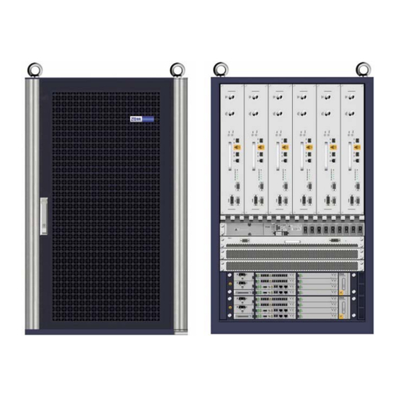
ZTE ZXSDR BS8800 C200 Installation Manual (167 pages)
CDMA Indoor Basestation
Brand:
ZTE
| Category:
Accessories
| Size: 3 MB
Table of Contents
Table of Contents
3
Preface
7
Safety Instruction
9
Safety Specifications Guide
9
Safety Symbols
10
Table 1 Safety Symbols Description
10
Safety Instructions
11
Installation Overview
15
Appearance
15
Engineering Indices
15
Figure 1 ZXSDR BS8800 C200 Appearance
15
Installation Flow
16
Table 2 ZXSDR BS8800 C200 Engineering Indices
16
Installation Precautions
17
Figure 2 Installation Flow
17
Installation Preparation
19
Cabinet Installation Environment Check
19
Equipment Room Space Requirements
19
Figure 3 Installation Space Requirement
20
Equipment Room Environment Requirements
21
Equipment Room Power Supply Requirements
22
Lightning and Grounding Requirements
23
Transmission Requirements
23
Wiring Requirements
24
Technical Material Preparation
25
Table 4 BENDING RADIUM REQUIREMENTS
25
Personnel Requirements
26
Tools and Instruments Preparation
26
Table 5 Tool and Meter List
26
Unpacking Acceptance
28
Counting Goods
28
Crate Unpacking
28
Carton Unpacking
29
Figure 4 Crate Unpacking
29
Acceptance and Goods Handover
30
Installing Cabinet
31
Cabinet Installation Flow
31
Installing Single-Cabinet
32
Figure 5 Cabinet Installation Flow
32
Figure 6 Single-Cabinet Installation Position
33
Figure 7 HOLING
33
Figure 8 INSULATION SLEEVE INSTALLATION
34
Figure 9 EXPANSION NUT INSTALLATION
34
Figure 10 INSULATION SHEET INSTALLATION
34
Figure 11 BASE INSTALLATION ASSEMBLY (1)
35
Figure 12 BASE INSTALLATION ASSEMBLY (2)
35
Figure 13 FIXING CABINET (1)
36
Figure 14 FIXING CABINET (2)
37
Figure 15 CABINET INSTALLATION COMPLETION
38
Installing Components
39
Module Position Schematic Diagram
39
Figure 16 Baseband-RF Cabinet Internal Structure
40
Installing RSU Module
41
Figure 17 RF SUBRACK APPEARANCE
41
Figure 18 BASEBAND SUBRACK APPEARANCE
41
Figure 19 SCREW POSITIONS on RF MODULE
42
Installing BBU
43
Figure 20 Screw Position
43
Figure 21 BBU Installation
44
Figure 22 M6×16 Screw Position
44
Installing BBU Horizontal Module
45
Figure 23 HORIZONTAL MODULE INSTALLATION
45
Installing BBU Vertical Module
46
Figure 24 Dustproof Assembly Installation
46
Figure 25 Vertical Module Installation
47
Installing Cable
49
On-Site Cable Installation List
49
Cable Installation Flow
50
Figure 26 Cable Installation Flow
50
Installing DC Power Cable
51
Figure 27 DC POWER CABLE APPEARANCE
51
Figure 28 DC Power Cable Inlet
52
Figure 29 Power Distribution Subrack Connection
53
Installing Grounding Cable
54
Figure 30 Power Cable Installation Completion
54
Installing Data Cable
55
Figure 31 Ground Cable Installation
55
Figure 32 Data Cable Appearance
56
Installing 75Ω E1 Cable
57
Figure 33 Data Cable Installation Completion
57
Figure 34 Abis/Iub Interface 75 Ω E1 Cable Appearance
58
Installing 120Ω E1 Cable
59
Figure 35 75 Ω E1 Cable Installation Completion
59
Installing 100Ω T1 Cable
60
Figure 36 120 Ω E1 Cable Appearance
60
Installing Abis Interface Ethernet Cable
61
Figure 37 100 Ω T1 Cable Appearance
61
Figure 38 Ethernet Cable Appearance
62
Installing Dry Contact Input/Output Cable
63
Figure 39 Abis Interface Ethernet Cable Layout
63
Figure 40 Dry Contact Input/Output Cable Appearance
64
Figure 41 Dry Contact Installation Completion
65
Installing RS232/RS485 Monitoring Cable
66
Figure 42 RS232/RS485 Monitoring Cable
66
Table 6 RS232/RS485 Monitoring Cable Description
66
Installing Fiber between BBU and RSU
67
Installing AISG Control Cable
67
Figure 43 Optical Fiber Appearance
67
Figure 44 AISG Control Cable Structure
68
Figure 45 AISG Control Installation Completion
68
Installing GPS Jumper
69
Figure 46 GPS Jumper Appearance
69
Figure 47 GPS Jumper Installation Completion
70
Installing RF Jumper
71
Figure 48 RF Jumper Installation Position
71
Installing GPS Antenna Feeder System
73
GPS Antenna Feeder System Installation Flow
73
Figure 49 GPS Antenna Feeder System Installation Flow
73
GPS Antenna Feeder System Installation Preparation
74
Installing GPS Antenna
74
GPS Antenna Installation Position
74
Figure 50 GPS Antenna Installation Position
74
Installing GPS Antenna in Vertical Placement
75
Figure 51 U-Shaped Clamp Installation
76
Installing GPS Antenna in Horizontal Placement
77
Figure 52 GPS Antenna Vertical Installation
77
Figure 53 GPS Antenna Rack Installation Support
78
Figure 54 GPS Rack Installation (Horizontal Placement)
78
Installing GPS Antenna in Wall-Mount Mode
79
Figure 55 GPS Antenna Fixed Horizontally
79
Figure 56 Design Template for Marking Holes
80
Installing GPS Feeder
81
GPS Feeder Selection Principle
81
Wiring GPS Feeder
81
Figure 57 GPS Antenna Fixed on Wall
81
Figure 58 Connection between Feeder to GPS Antenna
82
Installing GPS 1/4" Feeder Grounding Kit
83
Figure 59 GPS 1/4" FEEDER GROUNDING KIT STRUCTURE
84
Figure 60 1/4" FEEDER GROUND CABLE STRUCTURE
84
Leading GPS Feeder into Room
85
Installing Main Antenna Feeder System
87
Antenna Feeder System Installation Preparation
87
Foundational Facility Requirements
87
Checking Incoming Material
88
Making Feeder Connector
89
Figure 61 Strip off Sheath
89
Figure 62 O-Type Ring Location
89
Figure 63 Connection
90
Figure 64 Copper Scrap Clearness on the Cross Section
90
Assembling Omnidirectional Antenna
91
Figure 65 Rotating Connector Fastening Piece
91
Figure 66 Connecting Assembly
91
Figure 67 Omnidirectional Antenna Appearance
92
Figure 68 Fixing Omnidirectional Antenna
93
Assembling Directional Antenna
94
Figure 69 Directional Antenna Appearance
95
Figure 70 Directional-Antenna Fixation Clip
95
Figure 71 Depression Angle and Elevation Angle Adjustment
96
Hoisting Antenna and Feeder
97
Figure 72 Connection between Directional Antenna and
97
Installing Indoor Grounding Bar
98
Figure 73 Hoisting Antenna
98
Figure 74 Indoor Grounding Bar Structure
99
Figure 75 Indoor Grounding Bar Installation (1)
100
Figure 76 Indoor Grounding Bar Installation (2)
100
Installing Antenna
101
Installing Directional Antenna on Top-Tower
101
Figure 77 Arrester Protective Area
101
Figure 78 Iron Antenna Rack Structure (Unit: MM)
102
Figure 79 Antenna Rack Installation
103
Figure 80 Antenna Fixation Rack
104
Figure 81 Fixing Antenna
104
Figure 82 U-Shape Bolt
105
Figure 83 Kathrein Azimuth Adjustment Tools
105
Ing
106
Figure 84 Usage of Azimuth Adjustment Tool
106
Figure 85 Downtilt Measuring Instrument Appearance
106
Figure 86 Adjusting Downtilt
107
Installing Directional Antenna on Roof
108
Figure 87 Directional Antenna Installation on the Tower
108
Figure 88 Antenna Rack Structure
109
Figure 89 Antenna Rack Base Structure and Installation
110
Figure 90 Installing Antenna Rack on the Wall
111
Figure 92 Antenna Rack Fixed on the Wall ( Height of Wall Less than 1200 MM)
113
Figure 93 Fixation Rack
114
Figure 94 Fixing Antenna
114
Figure 95 U-Shape Bolt
115
Figure 96 Kathrein Azimuth Adjustment Tools
115
Figure 97 Usage of Azimuth Adjustment Tool
116
Figure 98 Downtilt Measuring Instrument Appearance
116
Figure 99 Adjusting Downtilt
117
Figure 100 Directional Antenna Installation on the Roof
118
Figure 101 Directional Antenna Installation on the Roof
118
Installing Omnidirectional Antenna on Top-Tower
119
Figure 102 Arrester Protective Area
119
Figure 103 Iron Antenna Rack Structure (Unit: MM)
120
Figure 104 Antenna Rack Installation
121
Figure 105 Omnidirectional Antenna Installation
122
Installing Omnidirectional Antenna on Roof
123
Figure 106 Omnidirectional Antenna Installation on the Iron
123
Figure 107 Antenna Rack Structure
125
Figure 108 Antenna Rack Base Structure and Installation
126
Figure 109 Installing Antenna Rack on the Wall
127
Figure 111 Antenna Rack Fixed on the Wall ( Height of Wall Less than 1200 MM)
129
Figure 112 Omnidirectional Antenna Installation
130
Installing Antenna Jumper
131
Figure 113 Omnidirectional Antenna Installation on the Roof
131
Figure 114 Jumper Connection
132
Figure 115 Feeder Kit Fixation
132
Installing Feeder Hermetic-Window
133
Figure 116 Installation Hole Positions (Unit: MM)
134
Installing and Grounding Feeder and Jumper
135
Feeder Cutting Principle
135
Figure 117 Hermetic Window Installation
135
Feeder Layout Principle
136
Installing Feeder on Tower
136
Table 7 Bending Radius Requirements of Various Feeders
136
Figure 118 Feeder Fixation on the Tower (One Kit and Two Fixation Clips)
137
Figure 119 Feeder Fixation on the Tower (One Kit and Three Fixation Clips)
137
Installing Feeder on Roof
138
Figure 120 Feeder Layout from Tower Top to Hermetic
138
Figure 121 Fixing Feeder into Fixation Clip
139
Feeder Grounding Principle
140
Figure 122 Feeder Layout from Roof to Hermetic Window
140
Figure 123 Feeder Grounding
141
Installing Feeder Grounding Kit
142
Figure 124 Grounding Kit Structure
142
Feeder Indoor Ingoing
143
Feeder Indoor Arrangement Principle
143
Figure 125 Waterproof Adhesive Tape Wrap
143
Leading Main Feeder into Room
144
Figure 126 Feeder into Room Mode (1)
144
Figure 127 Feeder into Room Mode (2)
145
Installing Top-Equipment Jumper
146
Performing Antenna Feeder System Test
147
Figure 128 Antenna, Feeder and Jumper Installation
147
Performing Outdoor-Connec Tor Waterproof Processing
148
Figure 129 Waterproof Insulation Adhesive Tape
148
Figure 130 PVC Adhesive Tape
149
Figure 131 Waterproof Insulation Adhesive Tape Wrap
149
Performing Feeder Hermetic-Window Waterproof
150
Processing
150
Figure 132 Connector after Processing
150
Figure 133 Feeder Hermetic-Window Dimension (Unit: MM)
151
Figure 134 12 Feeder Hermetic-Window Structure
151
Figure 135 Installation Hole Positions (Unit: MM)
152
Figure 136 Feeder Hermetic-Window Installation
153
Installation Check
155
Checking Equipment Installation
155
Cabinet Inspection Items
155
Cable Check Items
155
Socket, Plug and Locking Piece Inspection Items
156
Label Inspection Items
156
On-Site Environment Inspection Items
157
Checking Antenna Feeder System Installation
157
Checking Feeder
157
VSWR Test
158
Checking Water-Proof Processing
158
Checking Power on
159
Table 8 Distribution Subrack Panel Indicator Description
159
Figures
161
Tables
165
Advertisement
Advertisement
Related Products
Zte ZXSDR BS8800
ZTE ZXSDR BS8908 G060
Zte ZXSDR BS8900A GU360
Zte ZXSDR R8882
ZTE ZXSDR R8978
ZTE ZXSDR R8882 L268
ZTE ZXSDR R8881 S4200
Zte ZXSDR BS8800 C100
ZTE ZXSDR BS8802 C100
ZTE ZXSDR BS8900
ZTE Categories
Cell Phone
Modem
Wireless Router
Network Router
Switch
More ZTE Manuals
Login
Sign In
OR
Sign in with Facebook
Sign in with Google
Upload manual
Upload from disk
Upload from URL