
Related Manuals for Hioki ST5520-01


Summary of Contents for Hioki ST5520-01
- Page 1 ST5520 ST5520-01 Instruction Manual INSULATION TESTER Aug.2015 Revised edition 2 ST5520A981-02 15-08H...
-
Page 3: Table Of Contents
Contents Introduction ..................1 Verifying Package Contents .............1 Safety Notes ..................3 Usage Notes ..................7 Overview Product Overview and Features ...........15 ■ Overview .................... 15 ■ Features ..................... 16 Parts Names and Functions ..........17 1.3 Measurement Workflow ............19 1.4 Screen Configuration and Operation Overview ....20 ■ Measurement screen................20 ■... - Page 4 Contents Setting the Range ..............36 3.3 Switching the Measurement Speed (FAST/SLOW) .....38 3.4 Setting the Test Duration and Response Time ....39 ■ Setting how long to apply the test voltage .......... 39 ■ Setting the response time..............41 3.5 Judging Measured Values (Comparator function) ....44 Setting the Test Mode ............46 3.7 Announcing the Judgment Results Using a Beep Sound .47 Testing Starting Measurements ............49 During Measurement .............51 4.3 Measured Value Display ............52...
- Page 5 Contents 5.10 Default Setting List ..............73 Saving and Loading Measurement Conditions (Memory function) Saving the Measurement Conditions (Panel save function) .............76 Loading the Measurement Conditions (Panel load function) ..............77 Changing the Panel Name .............78 Deleting the Panel Data ............79 External Control (EXT.I/O) 7.1 External Input/Output Terminal and Signals......82 ■ Switching between current sink (NPN) and current source (PNP) ..82 ■...
- Page 6 Contents Communications (RS-232C interface) Interface Overview and Features ........113 Using the RS-232C Interface ..........114 ■ Setting communications conditions ..........114 ■ Connecting the RS-232C cable ............115 8.3 Automatically Exporting Measured Values at the Ends of Tests (Data output function) ........... 117 8.4 Controlling the Instrument and Acquiring Data with Commands ................119 ■ Remote and local states ..............119 ■...
- Page 7 Contents ■ Error display and solutions ............... 171 Appendix Appx.1 Appx. 1 Block Diagram ............Appx.1 Appx. 2 Contact Check Function ........Appx.2 Appx. 3 Output Voltage and Measurement Resistance ...Appx.3 Appx. 4 Influence of Capacitive Load .......Appx.4 Appx. 5 Influence of Cable Length ........Appx.6 Appx. 6 Influence of Noise ..........Appx.7 Appx. 7 Rack Mounting ............Appx.10 Appx. 8 Dimensional Diagram .........Appx.14 Index Ind.1...
- Page 8 Contents...
-
Page 9: Introduction
The ST5520-01 is equipped with the BCD output function of the ST5520. The artwork of the ST5520 is used in this manual. Verifying Package Contents When you receive the instrument, inspect it carefully to ensure that no damage occurred during shipping. - Page 10 Verifying Package Contents Options The following options are available for ST5520/ST5520-01. Contact your authorized Hioki distributor or reseller when ordering. L2200 Test Lead L9257 Connection Cord 9299 Switched Probe 9094 Output Cord (analog output) 9637 RS-232C Cable (9pin-9pin/1.8 m) 9638 RS-232C Cable (9pin-25pin/1.8 m)
-
Page 11: Safety Notes
Safety Notes Safety Notes This instrument is designed to conform to IEC 61010 Safety Standards, and has been thoroughly tested for safety prior to shipment. However, using the instrument in a way not described in this manual may negate the provided safety features. Before using the instrument, be certain to carefully read the following safety notes. - Page 12 Safety Notes Notation In this manual, the risk seriousness and the hazard levels are classified as follows. Indicates an imminently hazardous situation that will result in death or DANGER serious injury to the operator. Indicates a potentially hazardous situation that may result in death or WARNING serious injury to the operator.
- Page 13 Safety Notes Symbols affixed to the instrument Indicates cautions and hazards. When the symbol is printed on the instrument, refer to a corresponding topic in the Instruction Manual. Indicates that dangerous voltage may be present at this terminal. Indicates the power “ON”. Indicates the power “OFF”.
- Page 14 Safety Notes Measurement categories To ensure safe operation of measuring instruments, IEC 61010 establishes safety standards for various electrical environments, categorized as CAT II to CAT IV, and called measurement categories. DANGER • Using a measuring instrument in an environment designated with a higher-numbered category than that for which the instrument is rated could result in a severe accident, and must be carefully avoided.
-
Page 15: Usage Notes
Replace the probes with those specified by our company. • Before using the instrument the first time, verify that it operates normally to ensure that no damage occurred during storage or shipping. If you find any damage, contact your authorized Hioki distributor or reseller. Installation Installing the instrument in inappropriate locations may cause a malfunction of instrument or may give rise to an accident. - Page 16 Usage Notes Installation precaution CAUTION Do not position the instrument on an unstable table or inclined surface. If the instrument falls or tips, a malfunction of the instrument or injury may be caused. Handling the instrument DANGER To avoid electric shock, do not remove the instrument's case. The internal components carry high voltage and high temperature.
- Page 17 Before using the instrument, check that the coating of the cords are not either ripped or torn and that no metal parts are exposed. If any damage is found, contact your authorized Hioki distributor or reseller to prevent electric shock.
- Page 18 Usage Notes IMPORTANT When using the instrument, be sure to use the connecting lead wires, etc. specified by our company. When other cords and lead wires are used, accurate measurement may not be possible because the connection becomes poor, etc. Before connecting the power cord WARNING •...
- Page 19 Usage Notes Before connecting switched probes CAUTION To avoid damage to the probes, do not bend or pull the probe base. To ensure safe operation, use only the probes specified by our company. Residual risk WARNING The test leads generate high voltage. To avoid electric shock, do not touch the metal ends of the test leads.
- Page 20 Usage Notes Before connecting EXT.I/O WARNING • External power cannot be supplied to the instrument’s EXT.I/O connector. Do not apply external power. (The ISO_5V pin of the EXT. I/O connector is a 5 V (NPN)/-5 V (PNP) power output.) To avoid electric shock or damage to the equipment, always observe the following precautions when connecting to the EXT.I/O connector.
- Page 21 In the manual setting, a measured value does not stabilize unless the power frequency setting is switched properly. Precautions during shipment Observe the following during shipment. Hioki cannot be responsible for damage that occurs during shipment. CAUTION When shipping the instrument, use the packaging materials used when the instrument is delivered.
- Page 22 Usage Notes...
-
Page 23: Overview
Overview 1.1 Product Overview and Features Overview The HIOKI ST5520/ST5520-01 Insulation Tester is an insulation resistance tester that performs insulation resistance testing on components and equipment using direct current voltage. The test duration is 50 ms at the fastest and high speed testing can be performed. -
Page 24: Features
Product Overview and Features Features Test duration Judgment results can be displayed in 50 ms at the fastest. 50 ms (fastest) The test voltage can be selected from 25 V to 1000 V in increments of a resolution of 1 V. The comparator function (p. ... -
Page 25: Parts Names And Functions
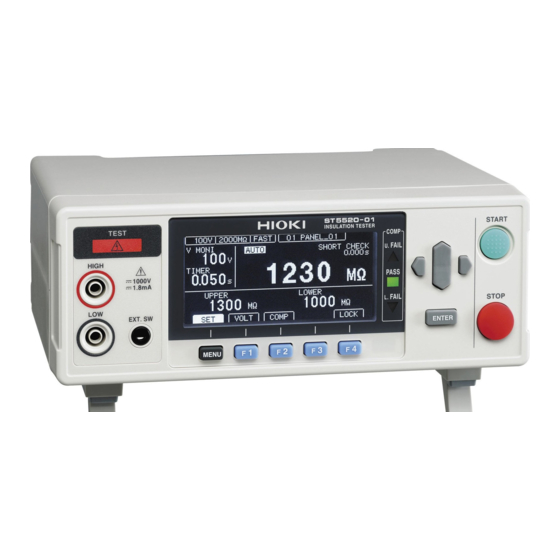
Parts Names and Functions 1.2 Parts Names and Functions Front panel Measurement terminals (p. 2 4) TEST lamp Display screen (p. 4 9) (Monochrome graphical LCD) Refer to p. 1 0. Cursor keys START STOP ENTER EXT.SW terminal (p. 1 09) For 9299 Switched Probe COMP lamps (p. ... - Page 26 Parts Names and Functions Bottom panel This instrument can be rack-mounted. Refer to “Appx. 7 Rack Mounting” (p. A ppx.10). The parts removed from this instrument should be stored in a safe place for future reuse. Side panel When using the stand Extend the legs all the way.
-
Page 27: Measurement Workflow
Measurement Workflow 1.3 Measurement Workflow Be sure to refer to “Usage Notes” (p. 7 ) before use. Preparing for measurement (p. 2 3) (Use the measurement terminals on the rear panel in case of 4-terminal measurements.) Checking before measurement (p. 2 7) Setting measurement conditions (p. ... -
Page 28: Screen Configuration And Operation Overview
Screen Configuration and Operation Overview 1.4 Screen Configuration and Operation Overview This instrument consists of a measurement screen and various settings screens. The screen examples in this manual appear reversed (black on white) for best visibility. The instrument screens, however, can actually be displayed only as white characters on a black background. -
Page 29: Settings Screen
Screen Configuration and Operation Overview Settings screen (MEAS screen) Setting the test voltage (p. 3 4) Setting the range (p. 3 6) Setting the measurement speed (p. 3 8) Setting the test duration (p. 3 9) Setting the response time (p. 4 1) Setting the test mode (p. ... - Page 30 Screen Configuration and Operation Overview (I/O screen) Setting the analog output range (p. 1 04) Setting the Switched Probe operation (p. 1 08) Setting the test signal OFF timing (p. 1 01) Setting the INTERLOC test function (p. 1 08) Setting the EXT.I/O test function (p. ...
-
Page 31: Preparations
Preparations 2.1 Connecting the Power Cord CAUTION To avoid electric shock and short circuits, use the voltage input cord supplied with the instrument. Power switch Check that the instrument power switch (rear panel) is OFF ( ). Check that the power supply voltage is within the display range (100 V to 240 V), and then connect the power cord to the power inlet. -
Page 32: Connecting The Measurement Leads
Connecting the Measurement Leads 2.2 Connecting the Measurement Leads Connect the optional Hioki measurement leads to the measurement terminals. Refer to “Options” (p. 2 ) for details. Use the measurement leads (optional) specified by our company. Connecting to the measurement terminals on the front panel... -
Page 33: Removing And Attaching The Sleeves
Connecting the Measurement Leads Removing and attaching the sleeves CAUTION The tips of the metal pins are sharp and may cause injury. Do not touch the tips. The metal tips of the test leads are covered with the removable sleeves. The test leads can be used without the sleeves. -
Page 34: Connecting To The Equipment To Be Measured
Connecting to the Equipment to be Measured 2.3 Connecting to the Equipment to be Measured WARNING To avoid electric shock and to maintain the safety specifications of this instrument, connect the power cord provided only to a 3-contact (two-conductor + ground) outlet. IMPORTANT •... -
Page 35: Pre-Operation Inspection
Before using the instrument the first time, check that it operates normally to ensure that no damage occurred during storage or shipping. If any damage is found, contact your authorized Hioki distributor or reseller. Accessory and optional equipment inspection Check item... -
Page 36: Checking The Insulation Resistance Test
Pre-Operation Inspection Checking the insulation resistance test Required items Recommended resistor: High voltage high resistance thick film resistor GS series Manufacturer: KOA Corporation or equivalent (Be careful with the working voltage and power.) CAUTION If the test voltage (power) exceeds the rated voltage (power) of the prepared resistor, the resistor may become damaged. -
Page 37: Checking The Contact Check Function
Pre-Operation Inspection Checking the contact check function WARNING Test leads generate high voltage. To avoid electric shock, do not touch the metal ends of the test leads. Check that the contact check function operates properly. Check the following three items. •... - Page 38 Pre-Operation Inspection Checking HIGH terminal contact To ensure safety, perform the following check with the HIGH side test leads removed. It is recommended to set test conditions as follows. Ω (Example) When the insulation resistance of the equipment to be measured is 100 M 25 V Test voltage Ω...
- Page 39 Pre-Operation Inspection Checking LOW side contact Perform the following check with the LOW terminal test leads removed. Turn off the instrument power. Connect the test leads to the HIGH terminals. HIGH (Do not connect the test leads to the LOW terminals.) For contact check...
- Page 40 Pre-Operation Inspection Checking the operation of the contact check function Turn off the instrument power. For contact check Connect the test leads to the LOW and HIGH terminals. HIGH Black Turn on the instrument power. Set the contact check function to [ON]. (p. ...
-
Page 41: Basic Settings
Basic Settings This chapter describes basic operation settings for the instrument. p. 3 4 “3.1 Setting the Test Voltage” ................ p. 3 6 “3.2 Setting the Range” ................. p. 3 8 “3.3 Switching the Measurement Speed (FAST/SLOW)” ......p. 3 9 “3.4 Setting the Test Duration and Response Time”... -
Page 42: Setting The Test Voltage
Setting the Test Voltage 3.1 Setting the Test Voltage Set the test voltage between 25 V and 1000 V. As the measurement range is set based on the test voltage, a measurement range that is not appropriate for the settings is switched automatically. The test voltage can be set in the Measurement or the settings screen. - Page 43 Setting the Test Voltage Setting the test voltage in the Settings screen Open the Settings screen. Select [SET]. [VOLTAGE] to edit mode. Selection Edit the value. Return to the Measurement screen. Change and then confirm the test voltage value. • Change the value. (Up/Down keys) • Change the cursor position.
-
Page 44: Setting The Range
Setting the Range 3.2 Setting the Range There are two range settings, auto and manual. For the manual range setting, the Ω Ω Ω Ω Ω range can be chosen from 2 M , 20 M , 200 M , 2000 M , and 4000 M . - Page 45 Setting the Range Setting the auto range Open the Settings screen. Select [SET]. [RANGE] to [AUTO]. When the auto range is set, [AUTO] is displayed in the Measurement screen. (p. 2 0) Selection [AUTO] Return to the Measurement screen.
-
Page 46: Switching The Measurement Speed (Fast/Slow)
Switching the Measurement Speed (FAST/SLOW) 3.3 Switching the Measurement Speed (FAST/ SLOW) There are two measurement speeds, [FAST] and [SLOW]. The resistance is measured and displayed in 30 ms when the measurement speed is set to [FAST] in 500 ms when the speed is set to [SLOW]. is effective if a measured value fluctuates Setting the measurement speed to [SLOW]... -
Page 47: Setting The Test Duration And Response Time
Setting the Test Duration and Response Time 3.4 Setting the Test Duration and Response Time Setting how long to apply the test voltage The test duration determines how long the test voltage will be applied. The same test duration is applicable at any test voltage. IMPORTANT •... - Page 48 Setting the Test Duration and Response Time [TIMER] to edit mode. Selection (Left and right keys) Edit the value. Return to the Measurement screen. Set the test duration. • Change the value. (Up/Down keys) • Change the cursor position. (Left and right keys) Confirm the value.
-
Page 49: Setting The Response Time
Setting the Test Duration and Response Time Setting the response time Response time is the time to prohibit comparator judgment after a test starts until the set response time elapses. No measured value is displayed during the response time. The response time is included in the test duration. The same response time is applicable at any test voltage. - Page 50 Setting the Test Duration and Response Time Setting to MANUAL Open the Settings screen. Select [SET]. [DELAY] to [MANUAL]. Selection [MANUAL] Return to the Measurement screen. [DELAY] to edit mode. Selection Edit the value. Return to the Measurement screen. Set the response time. •...
- Page 51 Setting the Test Duration and Response Time Setting to AUTO Open the Settings screen. Select [SET]. [DELAY] to [AUTO]. Selection [AUTO] Return to the Measurement screen.
-
Page 52: Judging Measured Values (Comparator Function)
Judging Measured Values (Comparator function) 3.5 Judging Measured Values (Comparator function) The following are enabled with the comparator function. • The instrument displays a judgment result (COMP lamp U.FAIL/PASS/L.FAIL). U.FAIL Upper limit value ≤ Measured value PASS Within judgment standard L.FAIL Lower limit value ≥... - Page 53 Judging Measured Values (Comparator function) Select [COMP]. Select [COMP]. Set the comparator function to [ON]. The comparator function can be set to ON and OFF for each of the upper and lower limit values. Select [ON/OFF]. (A value is displayed when ON is selected and “----”...
-
Page 54: Setting The Test Mode
Setting the Test Mode 3.6 Setting the Test Mode There are four test modes: Continuous test, PASS STOP, FAIL STOP, and Forced termination judgment. Open the Settings screen. Select [SET]. Set the test mode. Selection [CONT] [PASS] [FAIL] [SEQ] Return to the Measurement screen. -
Page 55: Announcing The Judgment Results Using A Beep Sound
Announcing the Judgment Results Using a Beep Sound 3.7 Announcing the Judgment Results Using a Beep Sound Judgment results are announced with a beep sound under the four conditions, OFF, PASS, FAIL, and END. Open the Settings screen. Select [SET]. Set the conditions for the beep sound. - Page 56 Announcing the Judgment Results Using a Beep Sound...
-
Page 57: Testing
Testing This chapter describes testing procedures for the instrument. 4.1 Starting Measurements WARNING Observe the following to avoid electric shock. • When the TEST lamp is blinking, do not touch the equipment to be measured, the tip of the probe, and measurement terminals. •... - Page 58 Starting Measurements • A test can be started or completed by the EXT.I/O, RS-232C, and switched probe in addition to the operation keys. A test can be started and completed by different methods. • Check that the test leads are securely connected before starting a test. •...
-
Page 59: During Measurement
During Measurement 4.2 During Measurement The instrument applies test voltage to equipment to be measured during measurement. (p. 3 9) When the test duration is set to [ON] 1. When the START key is pressed, test voltage is applied to the equipment to be measured, and the timer countdown starts. -
Page 60: Measured Value Display
Measured Value Display 4.3 Measured Value Display A measured value outside of the accuracy range can also be displayed. Measurement voltage Display range Ω Ω 25 V ≤ V 100 V 0.000 M to 400.0 M Ω Ω 100 V ≤ V 500 V 0.000 M to 4000 M Ω... -
Page 61: Completing Measurement
Completing Measurement 4.4 Completing Measurement WARNING To avoid electric shock, remove the measurement leads from an equipment to be measured after the TEST lamp is turned off after a test. Tests are completed by one of the following. • The STOP key is pressed, the EXT.I/O STOP signal is LOW, or a test completion command is sent from the RS-232C. -
Page 62: Automatic Discharge Function
Automatic Discharge Function 4.5 Automatic Discharge Function WARNING When an insulation resistance test is performed on equipment to be measured that contains capacitance components, a test voltage equivalent load is charged which may result in electric shock. A residual electric charge can be released through the internal circuit of the instrument. -
Page 63: Useful Functions
Useful Functions This chapter describes useful functions of the instrument. p. 5 6 “5.1 Checking Faulty Contact and Contact Status (Contact check function)” .. “5.2 Checking Short Circuit before Applying the Set Voltage (Short circuit p. 6 0 check function)” ..................... p. ... -
Page 64: Checking Faulty Contact And Contact Status (Contact Check Function)
Checking Faulty Contact and Contact Status (Contact check function) 5.1 Checking Faulty Contact and Contact Status (Contact check function) The faulty contact of the equipment to be measured and probes and the broken wires of the measurement cables are detected. The measurement terminals on the rear panel of the instrument are used for contact check. - Page 65 Checking Faulty Contact and Contact Status (Contact check function) Open the Settings screen. Select [SET]. [CONTACT CHECK] to [ON]. Selection [ON] [OFF] Return to the Measurement screen.
-
Page 66: Connecting Test Leads
Checking Faulty Contact and Contact Status (Contact check function) Connecting test leads Rear panel L2200 Connect the red plug to the HIGH terminal and the black plug to the LOW terminal. (The left and right side terminals are for contact check.) HIGH Black For contact check... -
Page 67: 2-Terminal Contact Check Function
Checking Faulty Contact and Contact Status (Contact check function) 2-terminal contact check function If the insulation resistance of the equipment to be measured is within the measurement range of the instrument, a 2-terminal contact check can be performed by setting the upper and lower limit values of the comparator. Ω... -
Page 68: Checking Short Circuit Before Applying The Set Voltage (Short Circuit Check Function)
Checking Short Circuit before Applying the Set Voltage (Short circuit check function) 5.2 Checking Short Circuit before Applying the Set Voltage (Short circuit check function) This is a function to check for short circuit by applying a low voltage (2 V to 4 V) to the equipment to be measured after starting a test and before applying the set voltage. - Page 69 Checking Short Circuit before Applying the Set Voltage (Short circuit check function) IMPORTANT • If the equipment to be measured contains electrostatic capacitance components, t1 becomes longer. Set the time using the automatic measurement function for short circuit check time. •...
- Page 70 Checking Short Circuit before Applying the Set Voltage (Short circuit check function) Setting to AUTO Open the Settings screen. Select [SET]. [SHORT CHECK] to [ON]. (When [ON] is selected, the [SHORT CHECK TIME] setting is displayed below.) Selection [ON] [OFF] Return to the Measurement screen.
- Page 71 Checking Short Circuit before Applying the Set Voltage (Short circuit check function) Ω • The short circuit check function is operated using 100 k as a criterion. Ω Therefore, if equipment operating at 100 k or less is measured, a short circuit check error occurs.
- Page 72 Checking Short Circuit before Applying the Set Voltage (Short circuit check function) [SHORT CHECK TIME] to edit mode. Selection Edit the value. Return to the Measurement screen. Set the test duration. • Change the value. (Up/Down keys) • Change the cursor position.
-
Page 73: Enabling/Disabling The Key Operations
Enabling/Disabling the Key Operations 5.3 Enabling/Disabling the Key Operations By executing the key lock function, the key operations other than UNLOCK, START STOP can be disabled. Disabling the key operations (Key lock engaged) Execute the key lock function. Key lock [LOCK] is displayed at the upper right corner and the key operations other than... - Page 74 Enabling/Disabling the Key Operations Enabling the key operations (Key lock cancelled) Cancel the key lock function. Reset key lock (hold down for 1 second). [LOCK] at the upper right corner disappears and the key operations are enabled.
-
Page 75: Setting The Key Operation Sound
Setting the Key Operation Sound 5.4 Setting the Key Operation Sound The key operation sound ON/OFF can be selected. In the default setting, the key sound is set to ON (beeps). Open the Settings screen. Select [SET]. [KEY CLICK] to [ON]. Selection [ON] [OFF]... -
Page 76: Preventing Operation Errors At The Start Of Testing (Double Action Function)
Preventing Operation Errors at the Start of Testing (Double action function) 5.5 Preventing Operation Errors at the Start of Testing (Double action function) This is a function to prevent operation errors at the start of test and ensure safer test. No tests start unless the START key is pressed within 1 s after the... -
Page 77: Adjusting The Screen Contrast
Adjusting the Screen Contrast 5.6 Adjusting the Screen Contrast The screen contrast can be set between 0 and 100% in increments of 5%. The screen may become difficult to see when ambient temperature changes. Open the Settings screen. Select [SET]. Set the value for [CONTRAST]. -
Page 78: Adjusting The Backlight
Adjusting the Backlight 5.7 Adjusting the Backlight The backlight brightness can be adjusted to the illumination of the installation location. The brightness can be set to 0 for communications. Be aware that the display may be difficult to see when the brightness is set to 0. Open the Settings screen. -
Page 79: Setting The Frequency Of Power Supply Manually
Setting the Frequency of Power Supply Manually 5.8 Setting the Frequency of Power Supply Manually There are three power supply frequency settings: AUTO, 50 Hz, and 60 Hz. To eliminate any noise, the supply power frequency needs to be set properly. In the default setting, the power supply frequency is supposed to be identified automatically (AUTO) when the power is supplied, however, it also can be set manually. -
Page 80: Initializing The System (Reset)
Initializing the System (Reset) 5.9 Initializing the System (Reset) All measurement conditions and panel data are reset to the default settings. There are three ways to reset. • Reset in the System Settings screen. • With the power off, turn on the power while pressing (MENU) and (up cursor key) at the same time. -
Page 81: Default Setting List
Default Setting List 5.10 Default Setting List Default Screen Setting and key Reference setting p. 4 4 COMP UPPER p. 4 4 COMP LOWER p. 6 5 LOCK p. 3 4 Settings Measurement VOLTAGE 25 V screen (SET) Settings screen p. ... - Page 82 Initializing the System (Reset)
-
Page 83: Saving And Loading Measurement Conditions (Memory Function)
Saving and Loading Measurement Conditions (Memory function) Panel save function The current measurement conditions can be saved. Up to 10 patterns of measurement conditions can be saved and retained even when the power is turned off. Settings that can be saved with the panel save function •... -
Page 84: Saving The Measurement Conditions (Panel Save Function)
Saving the Measurement Conditions (Panel save function) 6.1 Saving the Measurement Conditions (Panel save function) Open the Settings screen. Select [SET]. Select the panel number to be saved. The panel description is displayed on the right side of the screen. Selection Save the panel. -
Page 85: Loading The Measurement Conditions (Panel Load Function)
Loading the Measurement Conditions (Panel load function) 6.2 Loading the Measurement Conditions (Panel load function) The measurement conditions saved by the panel save function are loaded. Open the Settings screen. Select [SET]. Select and load the panel number. The panel description is displayed on the right side of the screen. Selection Load the panel. -
Page 86: Changing The Panel Name
Changing the Panel Name 6.3 Changing the Panel Name Open the Settings screen. Select [SET]. Select the panel number and select [RENAME]. Selection Edit the panel name. Return to the Measurement screen. Change and confirm the panel name. Confirm the panel name. -
Page 87: Deleting The Panel Data
Deleting the Panel Data 6.4 Deleting the Panel Data The measurement conditions saved by the panel save function are deleted. Open the Settings screen. Select [SET]. Select and delete the panel number. The panel description is displayed on the right side of the screen. Selection Delete the panel number. - Page 88 Deleting the Panel Data...
-
Page 89: External Control (Ext.i/O)
External Control (EXT.I/O) The EXT.I/O terminal on the rear panel of the instrument supports external control by providing output of the TEST and comparator judgment signals, and accepting input of the START and STOP signals. All signals are isolated with photocouplers. (The input/output common terminals are shared.) The input circuit can be switched to accommodate either current sink output (NPN) or current source output (PNP) by the internal settings of the instrument. -
Page 90: External Input/Output Terminal And Signals
External Input/Output Terminal and Signals 7.1 External Input/Output Terminal and Signals Switching between current sink (NPN) and current source (PNP) Before switching, thoroughly read “Before switching between current sink (NPN) and current source (PNP)” (p. 1 1). The EXT.I/O mode switch (NPN/PNP) allows you to change the type of PLC (programmable controller) that is supported. -
Page 91: Connector Type And Signal Pinouts
EXT.I/O operation. ST5520 17 16 15 14 13 12 11 10 9 8 7 6 5 4 3 2 1 Connector (instrument side) 37-pin D-sub (socket contacts) ST5520-01 with #4-40 screws Mating connectors • DC-37P-ULR (solder type) • DCSP-JB37PR (insulation... - Page 92 External Input/Output Terminal and Signals ST5520 Signal Signal Function Logic Pin Function Logic name name Measurement Measurement START Edge STOP Edge start (Not used) (Not used) Panel number INTERLOCK Interlock Level LOAD0 Level selection Panel number Panel number LOAD1 LOAD2 Level Level selection...
- Page 93 External Input/Output Terminal and Signals ST5520-01 Signal Signal Function Logic Pin Function Logic name name Measurement Measurement START Edge STOP Edge start (Not used) (Not used) Panel number INTERLOCK Interlock Level LOAD0 Level selection Panel number Panel number LOAD1 LOAD2...
-
Page 94: Signal Descriptions
It is output when the contact check function or the short circuit check function is set to ON. The decimal point position is output in 4 bits when BCD output is used. DP0 to DP2 (ST5520-01 only) A 4-digit and 16-bit measured value is output. BCD0 to BCD15 (ST5520-01 only) EXT.I/O input and output signals cannot be used while measurement conditions are... - Page 95 External Input/Output Terminal and Signals Signal correspondence chart LOAD0 to LOAD3 Panel LOAD2 LOAD1 LOAD3 LOAD0 number No change * External switch or transistor status Decimal point output Decimal point output 2000 200.0 20.00 2.000 * Internal photocoupler status BCD output BCD15 BCD12 BCD11...
-
Page 96: Timing Chart
Timing Chart 7.2 Timing Chart The each signal level indicates the ON/OFF status of a contact. In the current source (PNP) setting, the signal level is the same as the voltage level of EXT.I/O terminal. In the current sink (NPN) setting, the High and Low voltage levels are reversed. Set the signal before starting a test to control the measurement conditions at the EXT.I/O terminal (LOAD0 to LOAD3). - Page 97 Timing Chart /START (Input) /STOP (Input) t2 t6 /TEST (Output) When the TEST signal OFF timing setting is SLOW 10 V Test voltage Measurement stop Measurement, judgment Measurement-1 Measurement-2 (including contact check) Ω Measured value-1 Measured value-2 Measured 0/0.0/0.00 M Previous measured value value display Measured value-2 result...
- Page 98 Timing Chart Continuous test mode timing chart (2) When the test duration setting (TIMER) is ON and the measurement is performed by the /START signal input from EXT.I/O or when the test duration setting (TIMER) is ON and the measurement is performed by the START key on the panel Setting Test duration (TIMER) Response time (DELAY)
- Page 99 Timing Chart Item Time t1 START, STOP signal pulse width 5 ms MIN. t2 START, STOP signal detection time 5 ms MAX. AUTO, 5 ms to 999.9 s t3 Response time (DELAY) 30 ms (FAST), 480 ms (SLOW) t4 Measurement Contact check: OFF time 80 ms (FAST), 480 ms (SLOW)
- Page 100 Timing Chart /START (Input) /TEST (Output) When the TEST signal OFF timing setting is SLOW 10 V Test voltage Measurement end Measurement, judgment Measurement-1 Measurement-2 (including contact check) Ω Measured value-1 Measured value-2 Measured 0/0.0/0.00 M Previous measured value value display /PASS Previous result (Output)
- Page 101 Timing Chart FAIL STOP mode timing chart When the test duration setting (TIMER) is ON and the measurement is performed by the /START signal input from EXT.I/O or when the test duration setting (TIMER) is ON and the measurement is performed by the START key on the panel Setting Test duration (TIMER) Response time (DELAY) TEST signal OFF timing...
- Page 102 Timing Chart Item Time t1 START, STOP signal pulse width 5 ms MIN. t2 START, STOP signal detection time 5 ms MAX. AUTO, 5 ms to 999.9 s t3 Response time (DELAY) 30 ms (FAST), 480 ms (SLOW) t4 Measurement Contact check: OFF time 80 ms (FAST), 480 ms (SLOW)
- Page 103 Timing Chart /START (Input) /STOP (Input) t2 t6 /TEST (Output) When the TEST signal OFF timing setting is SLOW 10 V Test voltage Measurement end Measurement, judgment Measurement-1 Measurement-2 (including contact check) Ω Measured value-1 Measured value-2 Measured 0/0.0/0.00 M Previous measured value value display Previous result...
-
Page 104: Internal Circuit Configuration
Internal Circuit Configuration 7.3 Internal Circuit Configuration NPN setting Do not connect external power to pin 8. ST5520, ST5520-01 PLC, etc. ISO_5V Ω Ω START Output STOP Common EXT I/O Internally isolated MODE power supply PLC, etc. selector Ω Input... - Page 105 Internal Circuit Configuration PNP setting Do not connect external power to pin 8. ST5520, ST5520-01 PLC, etc. ISO_5V Ω Ω Output START STOP Common EXT I/O Internally isolated MODE power supply PLC, etc. selector Ω Input Zener voltage 30 V...
-
Page 106: Electrical Specifications
Internal Circuit Configuration Electrical specifications Input signals Input type Photocoupler-isolated, non-voltage contact inputs (Current sink/source output compatible) Residual voltage 1 V or less (Input ON current 4 mA (reference Input ON value)) OPEN (Shutoff current 100 µA or less) Input OFF Output signals Output type Photocoupler-isolated, open drain output (non-polar) Maximum load... -
Page 107: Connection Examples
Internal Circuit Configuration Connection examples Input circuit connection examples ST5520/ST5520-01 ST5520/ST5520-01 Input Input ISO_COM ISO_COM Switch connections Relay connections ST5520/ST5520-01 ST5520/ST5520-01 Input Output Input Output ISO_COM Common ISO_COM Common PLC output (NPN output) connections PLC output (PNP output) connections... - Page 108 Internal Circuit Configuration Output circuit connection examples ST5520/ST5520-01 ST5520/ST5520-01 Output Output 50 mA max 50 mA max ISO_COM ISO_COM 30 V max Relay connections LED connections ST5520/ST5520-01 ST5520/ST5520-01 Output Output 50 mA max Active-low Output logic output ISO_COM Active-low logic output...
-
Page 109: Setting The Test Signal Off Timing
Setting the TEST Signal OFF Timing 7.4 Setting the TEST Signal OFF Timing There are two timing options for the EXT.I/O TEST signal output to return from LOW to HIGH when a test is completed. Open the Settings screen. Select [SET]. Select the operation mode for [EXT.I/O TEST-PIN]. - Page 110 Setting the TEST Signal OFF Timing SLOW STOP Input Test voltage Approx. 10 V Generated TEST Output FAST STOP Input Test voltage Generated Stopped TEST Approx. 5 ms Output...
-
Page 111: Performing An I/O Test (Ext.i/O Test Function)
Checking External Control 7.5 Checking External Control Performing an I/O test (EXT.I/O test function) In addition to switching output signals between ON and OFF manually, the input signal status can be viewed on the screen. Open the Settings screen. Select [SET]. Select the operation mode for [EXT.I/O TEST]. -
Page 112: Using Analog Output
Using Analog Output 7.6 Using Analog Output There are two voltage output ranges of analog output. During a test, analog output is output at the same timing as the measured value display. After the test is completed, analog output continues to output and hold the final voltage. -
Page 113: Connecting The Output Cord
Using Analog Output Connecting the output cord The analog output terminal on the rear panel outputs direct voltage proportional to the resistance. When connecting to a recorder, etc., use an output cord with an input resistance of 1 Ω or more. When the input resistance is low, accurate measurement cannot be performed. -
Page 114: Interlock Function
Interlock Function 7.7 Interlock Function The interlock function is used to cut off any output from the instrument by linking with an external device. Once the interlock function is activated, all key operations are disabled. When the interlock function is enabled in the I/O screen of the EXT.I/O Settings screen, the interlock function runs when Pin 3 of EXT.I/O (INTERLOCK) is ON. - Page 115 Interlock Function The interlock function is activated. [ON] All key operations are disabled. In addition, no tests can be started using EXT.I/O, any command, or a switched probe. If the interlock function is changed to ON during the test, the test is stopped.
-
Page 116: Using The Switched Probe
(Trigger mode) switch is pressed during the test, the test is terminated. • For the operation of the ST5520 and ST5520-01 when the switched probe is used, refer to “Enabled/disabled input list” (p. 1 63). • The 9299 Switched Probe can be used as an ordinary probe when the switch... -
Page 117: Connecting The 9299 Switched Probe
When the TEST lamp blinks, press the push switch of the 9299 or the key of the ST5520/ Switch signal line plug STOP ST5520-01 to turn off the TEST lamp. Check that the TEST lamp is off and then HIGH connect the 9299 measurement plug to Measurement the HIGH terminal on the front panel. - Page 118 Using the Switched Probe Disconnecting the switched probe IMPORTANT When disconnecting the switched probe from the instrument, remove the switch signal line plug last. EXT.SW Switch signal line plug...
-
Page 119: Accessory Connector Assembly
• Connect the shield to the ISO_COM terminal of EXT.I/O. • If any of the supplied screws are missing or damaged, contact your authorized Hioki distributor or reseller. Required items • Screwdriver • Shielded cable •... - Page 120 Accessory Connector Assembly Screw (+/-) #4-40UNC (length: 16.9 mm) Nut #4-40UNC Covers (top and bottom with same shape) Retainer (for cable) Screw (+/-) #4-40UNC (length: 12.6 mm) Shielded cable (recommended) Connector Screw (-) #4-40UNC (length: 15.0 mm) Covers (top and bottom with same shape) Retainer (case protection)
-
Page 121: Communications (Rs-232C Interface)
Communications (RS-232C interface) Before connecting the communication cables, thoroughly read “Usage Notes” (p. 7 ). 8.1 Interface Overview and Features The communications interface can be used to control the instrument and acquire data. Refer to the section that is relevant to your application. •... -
Page 122: Setting Communications Conditions
Using the RS-232C Interface 8.2 Using the RS-232C Interface CAUTION • To avoid damage to the instrument, do not short connectors or output components or input voltage. • To avoid electric shock or damage to the instrument, turn off the instrument before connecting or disconnecting the RS-232C interface connectors. -
Page 123: Connecting The Rs-232C Cable
Using the RS-232C Interface Set the controller (computer or PLC, etc.). Make sure to set the controller as shown below. • Start-stop synchronization • Transfer speed: 9,600 bps / 19,200 bps / 38,400 bps (Set to match the instrument setting.) •... - Page 124 Instrument side computer Pin No. Pin No. Recommended cable: Hioki 9637 RS-232C Cable (9pin-9pin/1.8 m) When connecting a controller with a 25-pin D-sub port Use a crossover cable with a 9-pin D-sub (socket contacts) and a 25-pin D-sub (pin contacts) connector.
-
Page 125: Automatically Exporting Measured Values At The Ends Of Tests (Data Output Function)
Automatically Exporting Measured Values at the Ends of Tests (Data output function) 8.3 Automatically Exporting Measured Values at the Ends of Tests (Data output function) When a test is completed, the instrument can send measured values automatically as data to a computer via the RS-232C interface. If the START key is pressed with TYPE 1 or TYPE 2 selected, do not send any commands to the instrument until the computer receives the measured values. - Page 126 Automatically Exporting Measured Values at the Ends of Tests (Data output function) Preparing connected equipment (computer, PLC, or others) Set the equipment to the receive standby state. For a computer, start up the application software and set it to the receive standby state. Data output example TYPE1 Blank...
-
Page 127: Controlling The Instrument And Acquiring Data With
Controlling the Instrument and Acquiring Data with Commands 8.4 Controlling the Instrument and Acquiring Data with Commands For communications commands and query notation, refer to “8.6 Command Reference” (p. 1 26). When creating programs, the communications monitor function can be used to display commands and responses on the Measurement screen. Remote and local states During remote control operation, [RMT]... -
Page 128: Displaying Communications Commands
Controlling the Instrument and Acquiring Data with Commands Displaying communications commands (Communications monitor function) The communications monitor function can be used to display communications commands and query responses on the screen. Open the Settings screen. Select [SET]. [CMD MONITOR] to [ON]. Selection [ON] [OFF]... - Page 129 Controlling the Instrument and Acquiring Data with Commands Messages displayed in the communications monitor and their meanings If an error occurs during command execution, the following information is displayed. • Command error (improper command, improper argument format, etc.) > #CMD ERROR •...
- Page 130 Controlling the Instrument and Acquiring Data with Commands Command Format (1) Command Format The ST5520 commands have the following structure. Command (+Parameter) + Delimiter The command and the parameter are separated by “ “ ( one character space ) If there is no parameter, send the delimiter after the command. The command may consist of both upper and lower case letters.
- Page 131 Controlling the Instrument and Acquiring Data with Commands Command ON/OFF Some response commands are set with command setting ON/OFF. Use HEADer command to designate setting. The below is an example of the response command ON and command OFF. Example: Response when test voltage is set at 1000 V. :VOLTage? (Command querying current test voltage) Query:...
- Page 132 Controlling the Instrument and Acquiring Data with Commands Separators (1) Command unit separator Multiple commands can be written in a line by connecting them with a semicolon ; :VOLTage 1000;:RANGe AUTO;*IDN? Example: Multiple query commands can also be in a line. Response is returned in a line with each responding data separated by a semicolon ;...
-
Page 133: Data Format Table
Data Format Table 8.5 Data Format Table Measured value Ω 0.000E+06 to 4.000E+06 4 digits + decimal point range Ω 20 M 1.90E+06 to 9.99E+06 3 digits + decimal point range 10.00E+06 to 40.00E+06 4 digits + decimal point Ω 200 M 19.0E+06 to 99.9E+06 3 digits + decimal point... -
Page 134: Command Reference
Command Reference 8.6 Command Reference Command reference description :MOHM:RANGe <data> Syntax Reference Specifies the syntax for the command. <>: Specifies the description of the message data (text or numerical parameter). A response is returned in capital letters for a text parameter. Numerical parameter: NRf: Format including NR1, NR2, and NR3. - Page 135 Command Reference Command list Classification Command Function *CLS p. 1 29 Specialized Clears event resister *ESR? command p. 1 29 Queries event status resister *IDN? p. 1 30 Queries equipment ID *RST p. 1 30 Resets equipment :STARt p. 1 30 Testing status Starts a test :STOP...
- Page 136 Command Reference Classification Command Function :SHORtcheck p. 1 39 Short circuit check Sets short circuit check function :SHORtcheck? Queries short circuit check function p. 1 39 :SHORtcheck:TIME p. 1 39 Sets the short circuit check time :SHORtcheck:TIME? Queries the short circuit check time p. 1 40 :SHORtcheck:TIME p. ...
- Page 137 Command Reference Classification Command Function :HEADer p. 1 48 Command header Sets response command header ON/OFF function ON/OFF :HEADer? p. 1 48 Queries response command header ON/OFF :SYSTem:LOCal p. 1 49 Communications Resets remote state Lower-case characters in the commands are technically optional. The commands are case-insensitive.
- Page 138 Response *IDN? Example PC> HIOKI,ST5520,000012345,V1.00 ST5520> *RST Resets the instrument setting. When this command is executed during a test, the test is stopped and the setting is reset. The saved test conditions are also cleared. The interface setting is not initialized To reset the setting, refer to “5.10 Default Setting List”...
- Page 139 Command Reference :STATe? Returns the instrument status in numerical data (<data>). No command header is included in response. :STATe? Syntax <data> Response 0 to 2 (NR1 numerical data) <data> 0: Stopped, 1: Testing, 2: Discharging To query the status (during tests) Example :STATe? PC>...
- Page 140 Command Reference :MEASure:COMParator? Queries judgment result. When this command is received during tests, the judgment result is returned in text data (<data>). When the comparator function is OFF, OFF is always returned as a judgment result. When no judgment is made, NOCOMP is returned. When the response time timer is ON, DELAY is returned.
- Page 141 Command Reference :MEASure:CLEar Clears measured value and judgment result. The status is changed so that no judgment has been made. :MEASure:CLEar Syntax To clear the measured value and judgment result Example :MEASure:CLEar PC> :MEASure:MONItor? Queries the voltage monitor value. The rvoltage monitor value is returned in NR1 numerical data (<data>) No command header is included in response.
- Page 142 Command Reference :MOHM:RANGe Sets the resistance range. :MOHM:RANGe <data> Syntax 2 M / 20 M / 200 M / 2000 M / 4000 M / AUTO (text data) <data> Ω To set to 200 M Example range :MOHM:RANGe 200M PC> Ω...
- Page 143 Command Reference :TIMer Sets the test duration. Set 0.0 when the test duration is not to be set. During a test, the test is stopped and the test duration is set. :TIMer <data> Syntax Test duration (unit: second) 0.0 and 0.045 to 999.999 (resolution 0.001), <data>...
- Page 144 Command Reference :DELay? Queries the response time setting. The response time is returned in NR2 numerical data (<data>). 0.0 is returned when the response time is set to auto (AUTO). :DELay? Syntax :DELAY <data> <data> Response or simply Response time (unit: second) 0.0 and 0.005 to 999.999 (resolution 0.001) <data>...
- Page 145 Command Reference :COMParator:MODE Sets the comparator test mode. :COMParator:MODE <data> Syntax CONTinue, PASSstop, FAILstop, SEQuence (text data) <data> To set the test mode to FAIL STOP Example :COMParator:MODE FAILstop PC> :COMParator:MODE? Queries the comparator test mode. The test mode is returned in text data (<data>). :COMParator:MODE? Syntax :COMPARATOR:MODE <data>...
- Page 146 Command Reference :CONTactcheck Sets the contact check function ON/OFF. :CONTactcheck <data> Syntax ON/OFF (text data) <data> ON: The contact check function is enabled. OFF: The contact check function is disabled. To set the contact check function to ON Example :CONTactcheck ON PC>...
- Page 147 Command Reference :SHORtcheck Sets the short circuit check function ON/OFF. :SHORtcheck <data> Syntax ON/OFF (text data) <data> ON: The short circuit check function is enabled. OFF: The short circuit check function is disabled. To set the short circuit check function to ON Example :SHORtcheck ON PC>...
- Page 148 Command Reference :SHORtcheck:TIME? Queries the short circuit check time. The short circuit check time is returned in NR2 numerical data (<data>). 0.000 is returned when the short circuit check time is set to auto (AUTO). :SHORtcheck:TIME? Syntax :SHORTCHECK:TIME <data> <data> (NR2 numerical data) Response or simply...
- Page 149 Command Reference :KEY:BEEPer Sets the key beep sound ON/OFF. :KEY:BEEPer <data> Syntax ON/OFF (text data) <data> Example To set the key beeper to sound :KEY:BEEPer ON PC> :KEY:BEEPer? Queries the key beep sound ON/OFF setting. The beep sound ON/OFF setting is returned in text data (<data>).
- Page 150 Command Reference :DISPlay:CONTrast Sets the LCD contrast. :DISPlay:CONTrast <data> Syntax 0 to 100 (NR1 numerical data) <data> To set the contrast to 60 Example :DISPlay:CONTrast 60 PC> :DISPlay:CONTrast? Queries the LCD contrast. The setting is returned in NR1 number data (<data>). :DISPlay:CONTrast? Syntax :DISPLAY:CONTRAST <data>...
- Page 151 Command Reference :SYSTem:LFRequency Sets the power frequency. When AUTO is set, 50 Hz and 60 Hz are automatically identified. :SYSTem:LFRequency <data> Syntax AUTO/50/60 (text data) <data> AUTO: The power frequency is automatically identified. 50: Power frequency 50 Hz 60: Power frequency 60 Hz To set the power frequency to 60 Hz Example :SYSTem:LFRequency 60...
- Page 152 Command Reference :PANel:SAVE? Queries if the test conditions are saved with the specified number. Whether the test conditions are saved is returned in numerical data (<data2>). No command header is included in response. :PANel:SAVE? <data1> Syntax <data1> Test condition number 1 to 10 (NR1 numerical data) Response <data2>...
- Page 153 Command Reference :Panel:CLEar Deletes the test conditions. :Panel:CLEar <data1> Syntax <data1> Test condition number 1 to 10 (NR1 numerical data) To delete Test condition 1 Example :Panel:CLEar 1 PC> :AOUT:RANGe Sets whether the analog output is to be output in all measurement resistance ranges or in each range display area.
- Page 154 Command Reference :PROBe? Queries the 9299 Switched Probe operation mode setting. The continuous or trigger setting is returned in text data (<data>). :PROBe? Syntax :PROBE <data> <data> Response or simply CONTINUE/TRIGGER (text data) <data> CONTINUE: Continuous mode TRIGGER: Trigger mode Example To query the operation mode (when the operation mode setting is CONTINUE)
- Page 155 Command Reference :IO:ILOCk Sets the interlock function. IO:ILOCk <data> Syntax ON/OFF (text data) <data> ON: The interlock function is enabled. OFF: The interlock function is disabled. To set the interlock function to ON Example IO:ILOCk ON PC> :IO:ILOCk? Queries the interlock function setting. The ON or OFF setting is returned in text data (<data>). IO:ILOCk? Syntax IO:ILOCK <data>...
- Page 156 Command Reference :SYSTem:KLOCk? Queries the key lock setting. The ON or OFF setting is returned in text data (<data>). :SYSTem:KLOCk? Syntax :SYSTEM:KLOCK <data> <data> Response or simply ON/OFF (text data) <data> ON: The key lock is set. OFF: The key lock is cancelled. To query the key lock (when the setting is ON) Example :SYSTem:KLOCk?
- Page 157 Command Reference :SYSTem:LOCal Changes the communications remote state back to the local state. The key operation is enabled. :SYSTem:LOCal Syntax Example To cancel the remote state :SYSTem:LOCal PC>...
- Page 158 Command Reference...
-
Page 159: Specifications
Specifications Environment and safety Operating environment Indoors, pollution degree 2, altitude up to 2,000 m (6,562-ft.) Storage temperature -10°C to 50°C (-14°F to 122°F), 80% RH or less (no condensation) and humidity Operating temperature 0°C to 40°C (32°F to 104°F), 80% RH or less (no condensation) and humidity Dielectric strength 1.62 kV AC (sensed current 10 mA) for 1 minute... - Page 160 Charge (measurement) 1.8 mA current Short circuit current Less than 2.0 mA Analog output Not isolated against the power supply protective ground terminal and isolated against the measurement terminals. Output voltage: Switching between FULL and EACH 1. FULL 0 to 4 V is output in all measured resistance ranges. Output voltage Measurement voltage Displayed resistance...
-
Page 161: Resistance Measurement
Resistance measurement Ω Ω Ω Ω Ω Resistance range Manual range (2 M , 20 M , 200 M , 2000 M , 4000 M composition Auto range Range display The set range is displayed at the top of the screen. Rated Resistance Display... -
Page 162: Input
Resistance Commonly Applicable to FAST and SLOW measurement accuracy Rated measurement Guaranteed Basic accuracy voltage accuracy range Ω Ω 0.000 M to 2.000 M ±2% rdg. ±5 dgt. Ω Ω 25 V ≤ V < 100 V 1.90 M to 20.00 M Ω... -
Page 163: Test Duration
Test duration Definition of test Test duration = Response time + Measurement time duration Setting range Setting range 0.045 s (45 ms) to 999.999 s Test duration ON/OFF (- -) Display 000.000 s setting Screen display: 000.0 s, 0.000 s if less than 100 ms “000.0 s”... -
Page 164: Response Time
Response time Definition of No-judgment time response time Response time function Setting range AUTO, 0.005 s (5 ms) to 999.999 s Operation Comparator judgment is not performed after measurement starts until the response time elapses. The timer counts down along with the test duration timer (Test voltage is generated). - Page 165 Operation key, STOP No judgment is performed for forced termination (STOP signal). However, a judgement result is output when forced termination judgment mode is set. (No judgment is performed if the STOP key is pressed before one measurement, with an elapsed time of less than 45 ms, is not completed.) No LED display or EXT.I/O signal output.
- Page 166 Test mode Switch a mode selecting from continuous mode, PASS STOP mode, FAIL STOP mode, or forced termination judgment mode. • Continuous mode Measurement is performed for the specified test duration, judgment is performed for each measurement, the judgment result is output, and the output voltage is cut off.
-
Page 167: External Interface
Discharge and Any charge remaining in equipment to be measured is automatically remaining voltage discharged inside of the instrument when the testing is completed. warning The TEST lamp blinks during discharge and turns off when the voltage between the measurement terminals falls under 10 V ± 3 V. During a test: Blinking interval 250 ms During discharge: Blinking interval 500 ms... - Page 168 TEST signal OFF timing setting. The output transistor is ON at the time of a contact check error, short circuit error, output voltage error judgment (ST5520-01 only) DP0 to DP2 Decimal point output 3 bits (p. 8 7) BCD0 to BCD15 BCD output 4 digits, 16 bits (p. ...
- Page 169 ISO.COM Internal GND • External interface pin arrangement list (p. 8 4) (3) TEST signal OFF timing setting After a test, timing for the TEST signal output transistor to turn OFF from ON can be set. FAST The TEST signal turns OFF immediately after a test is completed without waiting for the voltage between the measurement terminals to drop.
-
Page 170: Other Specifications
Message terminator Receiving: CR+LF, CR (delimiter) Transmitting: CR+LF Flow control None Electrical specifications Input voltage levels 5 to 15 V: ON, -15 to -5 V: OFF Output voltage levels 5 to 9 V: ON, -9 to -5 V: OFF Connector Interface connector pinout (9-pin D-sub, pin contacts, with #4-40 attachment screws) The I/O connector is a terminal (DTE) configuration. - Page 171 Key combination Initialization (Turn on the power while pressing the MENU + Up keys.) Interlock cancellation (Turn on the power while pressing the MENU Down keys.) Enabled/disabled input list The following table shows the status (enabled/disabled) of the keys, switched probe, EXT.I/O, and RS command input.
-
Page 172: Accessories
External terminal (No switching between the measurement terminals on the front panel and those on the rear panel) Front Measurement terminals (HIGH, LOW), EXT.SW terminal Rear Measurement terminals (HIGH, LOW), EXT.I/O terminal, contact check terminals, RS-232C connector, analog output terminal, USB connector (maintenance terminal) Accessories Instruction manual ...................... -
Page 173: Maintenance And Service
• When shipping the instrument, use the packing materials used when the instrument was delivered. • Pack the instrument so that it is not damaged during shipping and include a description of existing damage. Hioki cannot be responsible for damage that occurs during shipping. Cleaning •... - Page 174 It is recommended to replace the parts so that the instrument can be used for a long period of time. Contact your authorized Hioki distributor or reseller for replacement parts. The lifetime of the parts varies depending on the operating environment and frequency of use.
-
Page 175: Troubleshooting
Even after short If the measured value is not displayed when the probe is circuit of the probe, short circuited, the fuse may have blown or been damaged. Contact your authorized Hioki distributor or reseller. the measured value does not appear. - Page 176 Troubleshooting Symptom Cause and solution Reference The power frequency setting may not be appropriate. Unstable p. 7 1 measured values Change the power frequency according to the customer environment. A load containing capacitance components may be connected. It may take time for the measured value to p. ...
- Page 177 Troubleshooting Others Symptom Cause and solution Reference The power may not be supplied. The power does not turn on. • Check the power cord. • Check that the facility breaker is on. • Turn on the power switch (rear side). The power voltage and frequency may not be correct.
- Page 178 A malfunction may have occurred. Contact your Error] authorized Hioki distributor or reseller. A voltage that is higher than the set voltage may be input during the test. Check that the equipment to be measured has been fully discharged.
-
Page 179: Error Display And Solutions
• If any damage is suspected, check “Troubleshooting” first and then contact your authorized Hioki distributor or reseller. • If an error is displayed in the LCD display and repair is required, contact your authorized Hioki distributor or reseller. Display... - Page 180 Troubleshooting Display Meaning Solution Reference ERR:004 Measurement Interlock error The test is canceled because the interlock function is activated during p. 1 06 aborted by interlock. the test. ERR:030 Command Check that the command is correct. Command error error. ERR:031 Execution Execution error.
-
Page 181: Appx
Appendix Appx. 1 Block Diagram Output Trance Switching power High Voltage Output supply Discharge circuit Voltage monitor EXT.I/O Contact check Current detection part RS-232C Analog output Analog Power Measurement block Control block • With our unique technology, the ripple component in the DC voltage is reduced and DC voltage is output without overshoot. -
Page 182: Appx. 2 Contact Check Function
Contact Check Function Appx. 2 Contact Check Function Route 3 Output terminal Output terminal Protective resistance HIGH side LOW side Equipment to Route 1 Route 2 be measured HIGH side LOW side High voltage Protective power supply resistance (Output voltage) Partial Partial Contact check terminals... -
Page 183: Output Voltage And Measurement Resistance
Output Voltage and Measurement Resistance Appx. 3 Output Voltage and Measurement Resistance 1200 1000 V 1000 500 V 200 V 100 V Ω Measured resistance [ Output voltage depends on measurement current 1.8 mA. If the equipment to be measured carries 1.8 mA or more, the voltage does not rise to the set output voltage. -
Page 184: Influence Of Capacitive Load
Influence of Capacitive Load Appx. 4 Influence of Capacitive Load Pure resistance is assumed in the instrument specifications, however, some capacitance components are contained in the equipment to be measured. The higher the resistance is (small detected current), the more variability the influence of a capacitive load causes. - Page 185 Influence of Capacitive Load FAST Voltage 25 V 50 V 100 V 250 V 500 V 1000 V Capacitance 0.001 µF ±1.0% ±1.0% ±1.4% ±1.3% ±1.3% ±1.4% 0.01 µF ±1.5% ±1.4% ±2.7% ±1.7% ±1.8% ±3.7% 0.05 µF ±3.0% ±2.5% ±7.0% ±3.0% ±5.8% ±7.7%...
-
Page 186: Influence Of Cable Length
Influence of Cable Length Appx. 5 Influence of Cable Length When the instrument is incorporated in a production line or automated machine, the measurement cable may be extended. When the measurement cable is extended, measured values can be affected by coupling capacitance between cables or line noise. -
Page 187: Influence Of Noise
Influence of Noise Appx. 6 Influence of Noise When induction noise is caused by commercial power supply Induction noise caused by a commercial power supply is generated by not only commercial power lines or power outlets but also by fluorescent lights and household electrical appliances. The noise caused by a commercial power supply depends on the frequency of the power supply and is generated at a frequency of 50 Hz or 60 Hz. - Page 188 Influence of Noise Influence of conductive noise In addition to inductive noise superimposed on the equipment to be measured or measurement leads, there is conductive noise. Conductive noise indicates noise superimposed on a power line or control line, such as a USB, etc. Various devices, including a motor, welder, inverter, etc.
- Page 189 Influence of Noise It is efficient to take measures for conductive noise by monitoring with the HIOKI 3145 Noise HiLogger. When the entry route is identified, taking the measures as shown in the figure below is effective. Isolation Controller (PC, PLC)
-
Page 190: Rack Mounting
Rack Mounting Appx. 7 Rack Mounting By removing the screws on the bottom, this instrument can be installed in a rack mounting plate. WARNING Observe the following precautions regarding the mounting screws to avoid instrument damage and electric shock accidents. •... - Page 191 Rack Mounting Rack Mounting Plate (JIS) Cold rolled steel sheet t2.0 2 × C2 4 × f5.4 Same shape at 4 locations Same shape at 4 locations Cold rolled steel sheet t2.0 4 × M5 press nuts Appx.
- Page 192 Rack Mounting M3 × 6 mm Extend the legs on the bottom of the instrument and remove the four screws. Affix the Rack Mounting Plate with the M3 × 6 mm screws. IMPORTANT When installing into the rack, support the installation with a commercially available support stand.
- Page 193 Rack Mounting Screw location dimensional drawing Appx.
-
Page 194: Dimensional Diagram
Dimensional Diagram Appx. 8 Dimensional Diagram 14±1 215±1 Appx. - Page 195 Index Automatic discharge function ..... 54 Key operation Disable ............ 65 Enable............. 66 Key operation sound........67 Backlight ............. 70 Block diagram ........Appx.1 Maintenance ..........161 Measured value Command Unstable........... Appx.4 Control ..........119 Measurement lead ........24 Data acquisition ........119 Make your own ........
- Page 196 Index Test duration ..........39 Testing Completing measurement....... 53 During measurement ......51 Starting measurements......49 Test mode ........... 46 TEST signal ........Test voltage ..........34 Timing chart ..........88 Troubleshooting ........163 Ind.
- Page 197 13-09...
Need help?
Do you have a question about the ST5520-01 and is the answer not in the manual?
Questions and answers