Table of Contents

Related Manuals for Hioki SM7810


Summary of Contents for Hioki SM7810
- Page 1 99 Washington Street Melrose, MA 02176 Phone 781-665-1400 Toll Free 1-800-517-8431 Visit us at www.TestEquipmentDepot.com Instruction Manual SM7810 SM7810-20 SUPER MΩ HiTESTER March 2012 Revised edition 1 SM7810A981-01 12-03H...
-
Page 2: Table Of Contents
Contents Contents Introduction.................1 Confirming Package Contents............1 Safety Information ..............2 Operating Precautions..............4 Chapter 1 Overview ___________________________________ 7 Product Overview and Features ......... 7 Operating Principles and Block Diagram ..........8 Names and Functions of Parts ..........9 Screen Layout ..............10 Chapter 2 Measurement Preparations___________________ 11 Installation &... -
Page 3: Contents
Contents Message List ..............33 Listener Specification Precautions ........40 Input buffer size ................40 Reading from the output buffer ............40 Chapter 5 External Control ____________________________ 41 External Input/Output Connector and Signals ....41 Connector Type and Signal Pinouts ..........42 ... -
Page 4: Introduction
Introduction Introduction Thank you for purchasing the HIOKI Model SM7810, SM7810-20 Super MΩ HiT- ester. To obtain maximum performance from the instrument, please read this manual first, and keep it handy for future reference. Confirming Package Contents When you receive the instrument, inspect it carefully to ensure that no damage occurred during shipping. -
Page 5: Safety Information
Safety Information Safety Information This instrument is designed to comply with IEC 61010 Safety Standards, and has been thoroughly tested for safety prior to shipment. However, mis- handling during use could result in injury or death, as well as damage to the instrument. - Page 6 Safety Information Other symbols Indicates a prohibited action. Indicates that descriptive information is provided below. PAGE Bold characters within the text indicate operating key labels. (Bold characters) (p. #) Indicates the location of reference information. Measurement categories (Overvoltage categories) To ensure safe operation of measurement instruments, IEC 61010 establishes safety standards for various electrical environments, categorized as CAT I to CAT IV, and called measurement categories.
-
Page 7: Operating Precautions
Before using the instrument for the first time, verify that it operates normally to ensure that no damage occurred during storage or shipping. If you find any dam- age, contact your dealer or Hioki representative. Instrument Installation Operating temperature and humidity: 0 to 40°C at 80%RH or less (non-condensing) - Page 8 Cable is undamaged and that no bare conductors are improperly exposed. Using the instrument in such conditions could cause an electric shock, so contact your dealer or Hioki representative for replacements. • Avoid stepping on or pinching cables, which could damage the cable insula- tion.
- Page 9 Operating Precautions Input and Measurement Precautions • The maximum input voltage and maximum rated voltage to earth are 1000 VDC. If their voltages are exceeded, this instrument will be damaged and personal injury will result. Therefore, do not input signals in excess of these values.
-
Page 10: Chapter 1 Overview
This insulation measuring instrument requires an external measurement power source to be provided by the operator. HIOKI offers a recommended power source (Model SM7860 series Power Source Unit). High-speed insulation resistance measurement... -
Page 11: Operating Principles And Block Diagram
1.1 Product Overview and Features Operating Principles and Block Diagram The instrument is an 8-channel, high-sensitivity ammeter for use in measuring insulation resistance. After connecting the dedicated external power source to the voltage input terminal (A) and applying voltage to the object under measurement from the voltage output terminals (OUTPUT), current is measured at the current input terminals (INPUT). -
Page 12: Names And Functions Of Parts
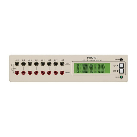
1.2 Names and Functions of Parts 1.2 Names and Functions of Parts Front Panel LCD screen Trigger indicator Measurement terminals The instrument’s interface consists Lights up when the trigger sig- of three display pages, including • INPUT: Current input terminals nal is on. -
Page 13: Screen Layout
1.3 Screen Layout 1.3 Screen Layout The LCD screen consists of three display pages. When the instrument is turned on, page 1 is shown. The scroll keys on the front of the instrument (PAGE UP▲/ PAGE DOWN▼) are used to scroll among the display pages, which can also be selected directly by sending the “... -
Page 14: Measurement Preparations
2.1 Installation & Connection Procedures Measurement Chapter 2 Preparations 2.1 Installation & Connection Procedures Be sure to read the "Operating Precautions" (p.4) before installing and connecting this instrument. Front Panel Rear Panel Be sure to complete the pre-oper- ation inspection (p.17) before Install this instrument (p.4) starting measurement Turn the power on (p.15) -
Page 15: Connecting The Power Cord
Using the instrument in such conditions could cause an electric shock, so contact your dealer or Hioki representative for replacements. To avoid damaging the power cord, grasp the plug, not the cord, when unplug- ging it from the power outlet. -
Page 16: Connecting The Measurement Cables
• Because the instrument performs high-sensitivity current measurement, noise occurring on the measurement cables may prevent measured values from sta- bilizing. Use low-noise shielded measurement cables that meet HIOKI’s speci- fications. For more information about measurement cables and voltage output cables,... -
Page 17: Connecting The Measurement Power Source
Rear Panel nal on the rear of the instrument. This insulation measuring instrument requires an external measurement power source provided by the operator. HIOKI offers a recommended power source (Model SM7860 series Power Source Unit). Specifications Voltage input pin assignments Pin No. -
Page 18: Turning The Power On And Off
2.5 Turning the Power On and Off 2.5 Turning the Power On and Off Before turning the instrument on, make sure the supply voltage matches that indicated on its power connector. Connection to an improper supply voltage may damage the instrument and present an electrical hazard. POWER switch Rear Panel Turning Power On... - Page 19 2.5 Turning the Power On and Off...
-
Page 20: Setting Measurement Conditions
When turning power on Do the “HIOKI”, “SM7810” and version num- The power cord may be damaged, or ber indications appear on the display area? the instrument may be damaged in- ternally. -
Page 21: Setting Measurement Conditions
3.2 Setting Measurement Conditions 3.2 Setting Measurement Conditions This section describes how to set measurement conditions according to the manner in which the instrument is to be used. Settings are configured via either of the instrument’s external interfaces: See: GP-IB/RS-232C Interface (p.19) The instrument cannot be configured directly in a standalone manner. -
Page 22: Communication (Gp-Ib/Rs-232C Interface)
4.1 Overview and Features Communication Chapter 4 (GP-IB/RS-232C Interface) The symbol shown below indicates that the following instructions are specific to the RS-232C or the GP-IB interface. Instructions without these symbols are for both the RS-232C and the GP-IB interface. : GP-IB only : RS-232C only Before Use... -
Page 23: Specifications
4.2 Specifications 4.2 Specifications Precautions RS-232C and GP-IB communications cannot be used simultaneously. GP-IB Specifica- Electrical machinery specifications: IEEE std. 488.1-1987 compliant tions Address setting : Can be set to talker/listener addresses 1 to 30. Interface Functions All Source Handshake functions ●... -
Page 24: Connect A Cable To The Gp-Ib Connector Or Rs-232C Connector
Using the GP-IB Interface Connect the GP-IB cable to the GP-IB connector. Recommended cable: Rear Panel HIOKI Model 9151-02 GP-IB Connector Cable (2 m) Using the RS-232C Interface Connect the RS-232C cable to the RS-232C connector. 1 2 3 4 5... - Page 25 When connecting the instrument to a computer Use a crossover cable with female 9-pin D-sub connectors. Crossover Wiring Female 9-pin Female 9-pin Recommended cable: D-sub D-sub Model SM7810, PC/AT-end HIOKI SM7810-20 end Model 9637 RS-232C Pin No. Pin No. Cable (1.8 m)
-
Page 26: Configuring The Communications Protocol
4.4 Configuring the Communications Protocol 4.4 Configuring the Communications Protocol Configuring GP-IB Interface Communications Setting the address Press and hold the scroll keys ( ) on the front of the instru- PAGE UP▲ PAGE DOWN▼ ment for about 7 seconds. (The address can be set from the P1, P2, or P3 screen.) ■... -
Page 27: Communication Methods
Messages can be either program messages, sent from the controller such as PC to the instrument, or response messages, sent from the instrument to the controller. Program Messages Message types are further categorized as follows Command Message SM7810 Controller Program Messages SM7810-20 Query Message... - Page 28 4.5 Communication Methods 3. Measurement data format RDT? The data format returned by the “ ” and “ ” commands can be set to any of the following three types by command: (1) Basic format Data is returned in channel order. Fields are separated by a data separator ( 1,±d.ddddE±dd,d,d,2,±d.ddddE±dd,d,d, 3,±d.ddddE±dd,d,d,4,±d.ddddE±dd,d,d,...
- Page 29 4.5 Communication Methods (2) Measured value only The status (c) and comparison results (d) are not added to the output data. Otherwise, this format is the same as the basic format. (3) Comparison results only The measured value (b) and status data (d) are not added to the output data. Otherwise, this format is the same as the basic format.
-
Page 30: Status Byte Register
4.5 Communication Methods Status Byte Register RS-232C reads the status bytes to find out the status of the instrument. The instrument adopts the IEEE488.1-1987 defined status model for parts related to the serial polling performed by the service request function. A trigger for generating a service request is called an event. - Page 31 4.5 Communication Methods Status Byte Register (STB) ______________________________________ A status byte register is an 8-bit register output from the unit to the controller dur- ing serial polling. If even one of the status byte register bits enabled by the ser- vice request enable register changes from "0"...
-
Page 32: Event Registers
4.5 Communication Methods Event Registers Standard Event Status Register (SESR) ____________________________ A standard event status register is an 8-bit register. If any bit in the Standard Event Status Register is set to 1 (after masking by the Standard Event Status Enable Register), bit 5 (ESB) of the Status Byte Register is set to 1. - Page 33 4.5 Communication Methods Standard Event Status Enable Register (SESER) ____________________ Setting any bit of the Standard Event Status Enable Register to 1 enables access to the corresponding bit of the Standard Event Status Register. Standard Event Status Register (SESR) and Standard Event Status Enable Register (SESER) bit 6 bit 5...
- Page 34 4.5 Communication Methods Device Event Status Register (DESR) and Device Event Status Enable Reg- ister (DESER) Status Byte Register (STB) bit 3 Device Event Status Register (DESR) bit 7 bit 6 bit 5 bit 4 bit 3 bit 2 bit 1 bit 0 −...
-
Page 35: Error Registers
4.5 Communication Methods Error Registers The Error Register, which consists of 8 bits, manages error information. The contents of this register are aggregated in the CME, EXE, DDE, and QYE bits of the Standard Event Status Register (no mask processing is performed). Error register-related message are listed below. -
Page 36: Message List
4.6 Message List 4.6 Message List RS-232C-only commands are indicated by When using the RS-232C interface to send commands, include a uniform wait time of 100 ms (excluding the following exceptions). <Exceptions> command: Requires a wait time of 8 s. command: Although the instrument can respond to the next command in 2.7 ms, the following wait times are required depending on the measurement speed in order to allow the instrument to wait for... - Page 37 4.6 Message List Command Description Formats Measurement ranges Current measurement range setting [Format] RNG d1,d2 AUTO/HOLD selection and HOLD range setting d1: NR1 format d1 (Selection: 0 to 1) d2: String 0: HOLD 1: AUTO d2 (HOLD range: string) Sets the current measurement range as a string. The current measurement ranges available for selection vary with the mea- surement speed setting.
- Page 38 4.6 Message List Command Description Formats Measurement voltage CH1 measurement voltage setting [Format] VM1 d1 d1: 0.1 to 1000.0 V d1: NR2 format CH1 measurement voltage query [Format] VM1? VM1? The contents of responses are the same as the settings. [Response] d1 CH2 measurement voltage setting [Format]...
- Page 39 4.6 Message List Command Description Formats Contact-check Contact check automatic execution mode selection [Format] CCM d1 d1 (Selection: 0 to 1) d1: NR1 format 0: OFF 1: ON Contact check automatic execution mode query [Format] CCM? CCM? The contents of responses are the same as the settings. [Response] d1 Target object capacitance setting [Format]...
- Page 40 4.6 Message List Command Description Formats Returns the fixture capacitance open correction value (fixture [Format] OST? d1 OST? capacitance) as a response. d1: NR1 format [Format] [Response] d1,d2,d3,d4, d1 (operation specification) d5,d6,d7,d8 0: Returns the capacitance without performing open correction. 1: Performs open correction and then returns the capacitance.
- Page 41 4.6 Message List Command Description Formats LCD display LCD display mode setting [Format] LCD d1 d1 (Display mode: 0 to 1) d1: NR1 format 0: OFF Display OFF 1: ON Display ON LCD display mode query [Format] LCD? LCD? The contents of responses are the same as the settings. [Response] d1 LCD display page specification [Format]...
- Page 42 Hardware ID query *IDN? [Format] *IDN? Returns the instrument’s hardware ID as the response. [Response] d1: String d1 (HIOKI E.E. CORPORATION, SM7810, 0, 01.00) *TRG [Format] Provides the same functionality as the GET message. *TRG *SAV Save environmental data...
-
Page 43: Listener Specification Precautions
4.7 Listener Specification Precautions 4.7 Listener Specification Precautions Input buffer size Multiple command messages can be transferred at once by joining them with message separators. Since the instrument provides an 128-byte input buffer, the instrument is unable to receive message strings in excess of 127 characters in length. -
Page 44: Chapter 5 External Control
5.1 External Input/Output Connector and Signals Chapter 5 External Control This chapter describes how to use the EXT I/O connector on the rear of the instrument to control the device. Connect the instrument’s EXT I/ O connector to the signal output or input device. -
Page 45: Connector Type And Signal Pinouts
5.1 External Input/Output Connector and Signals Connector Type and Signal Pinouts Rear Panel Connector • 57RE-40500-730B (50-pin: DDK) EXT I/O connector Signal name Signal name EXT_DCV2(+24V) EXT_DCV2(+24V) TRIG OPEN_IR C.CHECK OPEN_CX (Reserved) (Reserved) (Reserved) (Reserved) (Reserved) (Reserved) ALARM (Reserved) INDEX NO CONTACT1 NO CONTACT2 NO CONTACT3... -
Page 46: Signal Descriptions
5.1 External Input/Output Connector and Signals Signal Descriptions Input Signals EXT_DCV2(+24V) External power source input TRIG External trigger input signal C.CHECK Contact check input signal (p.52) OPEN_IR Fixture resistance open correction execution signal (p.53) OPEN_CX Fixture capacitance open correction execution signal (p.52) Output Signals This signal indicates the end of a measurement. -
Page 47: Timing Chart
5.2 Timing Chart 5.2 Timing Chart Each signal level indicates a corresponding voltage level. Normal measurement TRIG INDEX Contact- Measur T delay check ement NO CONTACT 1 to 8 HI 1 to 8 IN 1 to 8 Previous measurement results New measurement results LO1 to 8 Timing Chart Interval Descriptions... - Page 48 5.2 Timing Chart Fixture capacitance or fixture resistance open correction OPEN CX OPEN IR INDEX Timing Chart Interval Descriptions Interval Description Duration Pulse width (Low time) 100 μs or more INDEX, EOM delay time 400 μs or less OPEN CX : 8 ms typ T index (Measurement time) OPEN IR...
- Page 49 5.2 Timing Chart Contact-check C.CHECK INDEX NO CONTACT Previous measurement results New measurement results 1 to 8 Timing Chart Interval Descriptions Interval Description Duration Pulse width (Low time) 100 μs or more INDEX, EOM delay time 400 μs or less T index (Measurement time) 4 ms or less T eom...
-
Page 50: Internal Circuitry
5.3 Internal Circuitry 5.3 Internal Circuitry Input Circuit 24 VDC EXT_DC2 Input signals SM7810, SM7810-20 side External device side Output Circuit 5 to 24 VDC Output signals SM7810, SM7810-20 side External device side Input Signals Input type Contact input via photocoupler (negative logic) Input voltage LOW: 0 to 0.5 V, HIGH: 24 V±10%... - Page 51 5.3 Internal Circuitry...
-
Page 52: Chapter 6 Specifications
Power source Rated supply voltage Model SM7810 : 100 VAC, 110 VAC Model SM7810-20 : 220 VAC (Voltage fluctuations of ±10% from the rated supply voltage are taken into account) Rated supply frequency: 50/60 Hz Anticipated transient overvoltage: 2,500 V... -
Page 53: Basic Specifications
1 kΩ ±10% current meter Input/Output terminals Current input terminals (Front panel) :HIOKI proprietary input connector for IR meters Voltage output terminals (Front panel):Safety terminal (Red-colored) Voltage input terminals (Rear panel) :Special round connector Maximum input voltage:1000VDC (between each terminal) -
Page 54: Functions
6.3 Functions 6.3 Functions Measurement value indication Function Selects displayed value. Default state Resistance Settings Resistance * / Current *The resistance is calculated from the set measurement voltage and current value. Measurement speed Function Selects the measurement speed. Default state SLOW2 Setups FAST / MED (medium) / SLOW / SLOW2... - Page 55 6.3 Functions Measurement voltage Function Sets the measurement voltage. Default state 1.0 V Setup ranges 0.1 to 1000.0 V (0.1 V resolution) Fixture capacitance open correction function Function Measures the capacitance with the fixture in the open state (fixture capacitance). *This function must be executed before using the contact check function.
- Page 56 6.3 Functions Fixture resistance open correction function Function Measures the current of the fixture in the open state and corrects measured values. Default state Setups OFF / ON Backup Function Function Backups up certain items. Backup Items Environmental data (measurement speed, trigger delay time, measured value display settings, averaging settings, averaging count, measurement voltage setting, power source frequency, current range, current range switching setting, comparative mea- surement setting, comparative measurement upper and lower limits, contact check au-...
-
Page 57: Measurement Specifications
6.4 Measurement Specifications 6.4 Measurement Specifications Accuracy Conditions of guaranteed accuracy Warm-up time 1 hour or more Temperature and humidi- 23±5°C, 80%RH or less (non-condensing) ty range for guaranteed accuracy Averaging settings Period of guaranteed 1 year accuracy... - Page 58 6.4 Measurement Specifications Accuracy DC current measurement accuracy Measurement Current accuracy Resistance accuracy Range speed ±(percent of reading) ±(percent of reading) − − FAST 5.0 + 15 × 10 - + 5.0 + 15 × 10 - / Im + 100 × Vofs / Vs / Vs 100 pA...
- Page 59 6.4 Measurement Specifications Measurement time Power Source Frequency 50 Hz 60 Hz Contact Measurement Comparator INDEX [ms] EOM [ms] INDEX [ms] EOM [ms] -check speed FAST 24.0 21.0 INDEX + 0.1 ms INDEX + 0.1 ms 100.0 84.0 SLOW 320.0 320.0 SLOW2 FAST...
-
Page 60: Input / Output Functions (Interface For External Control)
6.5 Input / Output Functions (Interface for External Control) 6.5 Input / Output Functions (Interface for External Control) GP-IB Interface Data reception Settings Environmental data (measured value display mode, measurement speed, measure- ment range, trigger delay time, averaging, power source frequency, measurement volt- age, contact check execution mode, target object capacitance setting, LCD display mode, current channel setting) Control... - Page 61 6.5 Input / Output Functions (Interface for External Control) External I/O Input/Output signals Input Signal types Trigger (TRIGGER), fixture capacitance open correction execution (OPEN_CX), fixture resistance open correction execution (OPEN_IR), contact check execution (C.CHECK) Input method Photocoupler-isolated input Electrical specification LOW: 0.5 V or less HIGH: 24 V±10% Output...
-
Page 62: Maintenance And Service
If the instrument seems to be malfunctioning, confirm that the cables and fuse are not open circuited before contacting your dealer or Hioki representative. Transporting Pack the instrument so that it will not sustain damage during shipping, and include a description of existing damage. -
Page 63: Replacing The Power Fuse
7.2 Replacing the Power Fuse 7.2 Replacing the Power Fuse • To avoid electric shock, turn off the power switch and disconnect the connection cables before replacing the fuse. • Replace the fuse only with one of the specified characteristics and volt- age and current ratings. -
Page 64: Error Displays
7.3 Error Displays 7.3 Error Displays Error Display Description Remedy Please contact your dealer or Hioki repre- ERROR:001 Call Service Center Backup data corrupt sentative. Please contact your dealer or Hioki repre- ERROR:002 Call Service Center Backup data write failure sentative. - Page 65 7.4 Cleaning...
-
Page 66: Appendix
Appendix 1 Attaching Rubber Feet Appendix Appendix 1 Attaching Rubber Feet The instrument ships with four rubber feet. Attach the rubber feet to the base of the instrument as necessary. When attaching the rubber feet, refer to the following diagram for a rough indica- tion of how the feet should be positioned. -
Page 67: Appendix 2 Rack Mounting
Appendix 2 Rack Mounting Appendix 2 Rack Mounting You can remove the screws on the sides of the instrument and attach rack mounting brackets. To avoid damage to the instrument or an electrical accident, be sure to observe the following precautions on using screws. •... - Page 68 Appendix 2 Rack Mounting Reference Diagrams and Attachment Procedure for Rack Mounting Brackets Rack Mounting Bracket (JIS) Spacers (Use 2) Rack mounting brackets M4 × 10 mm Spacers Insert spacers on both sides of the instrument and attach the mounting brackets with M4 ×...
-
Page 69: Appendix 3 External Dimensions
Appendix 3 External Dimensions Appendix 3 External Dimensions Test Equipment Depot - 800.517.8431 - 99 Washington Street Melrose, MA 02176 TestEquipmentDepot.com...
Need help?
Do you have a question about the SM7810 and is the answer not in the manual?
Questions and answers