Sign In
Upload
Manuals
Brands
Hioki Manuals
Test Equipment
ST5520-01
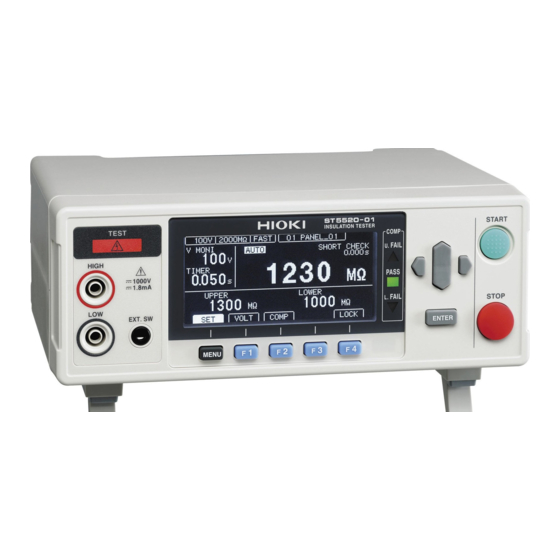
User Manuals: Hioki ST5520-01 Resistance Tester
Manuals and User Guides for Hioki ST5520-01 Resistance Tester. We have
1
Hioki ST5520-01 Resistance Tester manual available for free PDF download: Instruction Manual
Hioki ST5520-01 Instruction Manual (201 pages)
Brand:
Hioki
| Category:
Test Equipment
| Size: 6 MB
Table of Contents
Table of Contents
3
Introduction
9
Verifying Package Contents
9
Safety Notes
11
Usage Notes
15
Overview
23
Product Overview and Features
23
Overview 15
23
Features
24
Parts Names and Functions
25
Measurement Workflow
27
Screen Configuration And Operation Overview
28
Measurement Screen
28
Settings Screen
29
Preparations
31
Connecting the Power Cord
31
Preparations 23
31
Connecting the Measurement Leads
32
Removing and Attaching the Sleeves
33
Connecting To The Equipment To Be Measured
34
Turning on the Power
34
Turning the Power on and off
34
Turning off the Power
34
Pre-Operation Inspection
35
Checking the Insulation Resistance Test
36
Checking the Contact Check Function
37
3 Basic Settings 1
41
Setting the Test Voltage
42
Setting the Range
44
Switching The Measurement Speed (Fast/Slow)
46
Switching the Measurement Speed (FAST/SLOW
46
Setting The Test Duration And Response Time
47
Setting the Test Duration and Response Time
47
Setting How Long to Apply the Test Voltage
47
Setting the Response Time
49
Judging Measured Values (Comparator Function)
52
Judging Measured Values (Comparator Function
52
Setting the Test Mode
54
Announcing The Judgment Results Using A Beep Sound
55
Announcing the Judgment Results Using a Beep Sound
55
Testing
57
Starting Measurements
57
During Measurement
59
Measured Value Display
60
Completing Measurement
61
Automatic Discharge Function
62
5 Useful Functions 1
63
Checking Faulty Contact and Contact Status (Contact Check Function)
64
Checking Faulty Contact and Contact Status (Contact Check Function
64
Connecting Test Leads
66
Example of Connection to Equipment to be Measured
66
2-Terminal Contact Check Function
67
Checking Short Circuit before Applying the Set Voltage
68
Checking Short Circuit before Applying the Set Voltage (Short Circuit Check Function)
68
Enabling/Disabling The Key Operations
73
Enabling/Disabling the Key Operations
73
Setting The Key Operation Sound
75
Setting the Key Operation Sound
75
Preventing Operation Errors at the Start of Testing (Double Action Function)
76
Preventing Operation Errors at the Start of Testing (Double Action Function
76
Adjusting The Screen Contrast
77
Adjusting the Screen Contrast
77
Adjusting The Backlight
78
Adjusting the Backlight
78
Setting The Frequency Of Power Supply Manually
79
Setting the Frequency of Power Supply Manually
79
Initializing The System (Reset)
80
Initializing the System (Reset
80
Default Setting List
81
Saving and Loading Measurement Conditions (Memory Function)
83
Saving the Measurement Conditions (Panel Save Function)
84
Loading the Measurement Conditions (Panel Load Function)
85
Changing the Panel Name
86
Deleting the Panel Data
87
External Control (EXT.I/O)
89
External Input/Output Terminal And Signals
90
Switching between Current Sink (NPN) and Current Source (PNP)
90
Connector Type and Signal Pinouts
91
Signal Descriptions
94
Timing Chart
96
Internal Circuit Configuration
104
Electrical Specifications
106
Connection Examples
107
Setting the TEST Signal off Timing
109
Performing an I/O Test (EXT.I/O Test Function)
111
Checking External Control
111
Using Analog Output
112
Connecting the Output Cord
113
Setting the Analog Output
113
Interlock Function
114
Using The Switched Probe
116
Connecting the 9299 Switched Probe
117
Accessory Connector Assembly
119
Communications (RS-232C Interface)
121
Interface Overview and Features
121
Setting Communications Conditions
122
Using the RS-232C Interface
122
Connecting the RS-232C Cable
123
Automatically Exporting Measured Values at the Ends of Tests (Data Output Function)
125
Controlling The Instrument And Acquiring Data With
127
Remote and Local States
127
Commands
127
Displaying Communications Commands
128
Function)
128
Data Format Table
133
Command Reference
134
Specifications
159
Environment and Safety
159
Output (Output Accuracy)
159
Resistance Measurement
161
Input
162
Guaranteed Accuracy
162
Test Duration
163
Response Time
164
Functions
164
External Interface
167
Other Specifications
170
Accessories
172
Options
172
Maintenance and Service
173
Maintenance
173
Troubleshooting
175
Error Display and Solutions
179
Appx
181
Block Diagram
181
Appendix Appx.1
181
Appx
182
Output Voltage And Measurement Resistance
183
Appx. 2 Contact Check Function
182
Contact Check Function
182
Appx
183
Influence Of Capacitive Load
184
Appx
184
Influence Of Cable Length
186
Appx
186
Influence Of Noise
187
Appx
187
Appx. 6 Influence of Noise
187
Rack Mounting
190
Appx
190
Dimensional Diagram
194
Appx. 8 Dimensional Diagram
194
Advertisement
Advertisement
Related Products
Hioki ST5540
Hioki ST5541
Hioki ST5520
Hioki SM7810
Hioki SM7810-20
Hioki ST4030
Hioki ST4030A
Hioki ST5680
Hioki SR-2
Hioki ST4200
Hioki Categories
Measuring Instruments
Test Equipment
Data Loggers
Multimeter
Accessories
More Hioki Manuals
Login
Sign In
OR
Sign in with Facebook
Sign in with Google
Upload manual
Upload from disk
Upload from URL