Sign In
Upload
Manuals
Brands
BOC Edwards Manuals
Water Pump
iL600
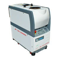
BOC Edwards iL600 Dry Vacuum Pump Manuals
Manuals and User Guides for BOC Edwards iL600 Dry Vacuum Pump. We have
1
BOC Edwards iL600 Dry Vacuum Pump manual available for free PDF download: Instruction Manual
BOC Edwards iL600 Instruction Manual (146 pages)
Dry Pumpings Systems
Brand:
BOC Edwards
| Category:
Water Pump
| Size: 1 MB
Table of Contents
Table of Contents
4
Title
5
1 Introduction
10
Scope and Definitions
10
Overview
11
The Il System
11
Applications
13
The LCDP Dry Pump
13
The LCDP Gas System (Sensor-Configured Il Systems Only)
13
The LCMB Mechanical Booster Pump (Il600 Only)
14
Temperature Control System
14
LCDP Pump Temperature Control System
14
LCMB Pump Temperature Control System (Il600 Only)
15
Exhaust System
16
Electrical System
16
Introduction
16
Electrics and Pump Control Module
16
Schematic Diagram of the Electrical System
18
Services and Electrical Connections on the Rear of the Il System
21
Electrical Components (Shown Without Enclosure for Clarity)
23
Sensor Monitoring Module (Sensor-Configured Il Systems Only)
24
Gas Module (Sensor-Configured Il Systems Only)
24
Controls and Indicators
24
Control Functions
25
Priority of Control
25
Setpoints, Warning and Alarm Conditions
26
Safety Sensors
26
Pump Display Module (Optional Accessory)
27
Accessories
29
2 Technical Data
30
General
30
Performance
30
Technical Data
31
Il70 Dimensions (MM)
32
Il600 Dimensions (MM)
33
Services Connections Dimensions (MM)
34
Centre of Mass Dimensions (MM) and Mass Distribution
35
Typical Pumping Speeds for Il70: Pumping Speed against Pressure
36
Il70 Power Curves: Electrical Power Input against Inlet Pressure
37
Temperature Control System
38
Cooling-Water Supply
38
Lubrication
39
LCDP Pump
39
LCMB Pump (Il600 Only)
39
Electrical Data
39
Full Load Current Ratings
39
Gas System (Sensor-Configured Il Systems Only)
40
Construction Materials
40
Default Setpoints
41
Connections
41
Sensor Monitoring Module Default Setpoints (Sensor-Configured Il Systems Only)
42
Item Numbers
43
Standard Il Systems
43
Sensor-Configured Il Systems
43
3 Installation
44
Safety
44
Installation Checklist
44
Unpack and Inspect
46
Checklist of Components
47
Lifting-Bolt Positions
48
Reconfigure the Nitrogen and Cooling-Water Connections (if Required)
49
Remove the Enclosure Panels
49
Remove/Refit the Enclosure Panels
50
Reconfigure the Cooling-Water Connections (if Required)
52
Locate the Il System
53
Check the Pump Oil-Level(S)
54
Check the Pump Oil-Levels
54
Il600 Systems
54
Il70 Systems
54
Install or Replace the Pump Display Module and Other Optional Accessories (if Necessary)
54
Install the Pump Display Module (Optional)
54
Connect the Il Inlet to Your Vacuum System
55
Install Other Optional Accessories
55
Fit the Pump Display Module (Optional Accessory)
56
Connect the Il Exhaust Outlet to Your Exhaust Extraction System
57
Connect the Il Exhaust Outlet to Your Exhaust-Extraction System
57
Connect to Your Factory Extraction System (Optional)
57
Connect the Nitrogen Supply (Sensor-Configured Il Systems Only)
58
Leak Test the System
58
Connect to Your Emergency Stop Circuit (Optional)
59
Install Additional Safety Equipment (Optional)
59
Leak-Test Port Position
60
Electrical Supply and RF Earth (Ground) Connections
61
Reconfigure the Il System for Your Electrical Supply (if Necessary)
61
Reconfigure the Pump(S) for Your Electrical Supply (if Necessary)
61
Reconfigure the Il System for Your Electrical Supply (if Necessary)
62
Connect the Electrical Supply to the Il System
63
Reconfigure the Pump-Motor Terminal-Box (if Necessary)
64
Connect an Additional RF Earth (Optional)
65
Refit the Enclosure Panels
65
Connect the Electrical Supply Cable to the Connector Mating-Half
66
Connect the Cooling-Water Pipelines
67
Commission the Il System
68
Switch on an Il70 System
68
Configure and Switch on an Il600 System
69
Pump Display Module Menus and Display Formats
72
Introduction
72
General Operation
73
Display Text and Variable Text
74
The CANCEL Button
74
Example
75
Menu Structure
75
Timeout
75
Wrap-Around
75
Menu Structure
76
Switch on
77
Switch off
77
Menu Logic
77
Normal
78
Switch on Menu
78
Switch off Menu
79
Normal Menu
80
Status
81
Status Menu: Sheet 1 of 2
81
Control
83
Control Menu
83
Setup
84
Setup Menu: Sheet 1 of 3
84
Inlet Purge
85
Gas Ballast
85
Run Til Crash
87
Units
88
Units Menu
88
Normal Display
89
Service
90
Service Menu: Sheet 1 of 2
90
Serial Numbers
91
Serial Menu
92
Zero Sensors
93
Gas Valve Contrl
94
Manual
95
Manual Menu: Sheet 1 of 3
95
View Status
98
Messages
100
Messages Menu
100
Warning and Alarm Messages Menu
101
Operation
102
Change the Display Format
102
Change the Normal Display
102
Introduction
102
Change the Display Units
103
Take and Release Control
103
Start-Up
104
Check the Nitrogen Pressure and Adjust if Necessary (Sensor-Configured Il Systems Only)
105
Monitor the Status of the Il System
105
Status Menu Display Options
106
Warning and Alarm Indications
107
Manual Shut-Down
107
Normal Manual Shut-Down
107
Fast Manual Shut-Down
108
Automatic Shut-Down
108
Emergency Stop
109
Restart the LCMB Pump after Automatic Pump Shut-Down (Il600 Only)
109
Restart the Il System after Emergency Stop or Automatic Shut-Down
110
Operation of Il System Components
110
Operation of the Load-Lock Pump
111
Maintenance
112
Safety
112
General Requirements
112
Recommended Purge Method
113
Correct Use of Swagelok Connectors
113
Fit a Swagelok Fitting
114
Reconnect Swagelok Connector
115
Maintenance Frequency
115
Inspect the Connections, Pipelines, Cables and Fittings
115
Inspect and Clean the Exhaust-Pipe and Check-Valve
116
Dismantle, Clean and Refit the Exhaust-Pipe
116
Clean and Refit the Check-Valve (if Fitted)
117
Clean the Exhaust Check-Valve
118
Check the LCMB Pump Oil-Level (Il600 Only)
119
Check the LCDP Pump Oil-Level
120
Change the LCDP Pump Oil
121
Change the LCMB Pump Oil (Il600 Only)
122
Adjust the Pump Display Module Display Viewing Angle (if Fitted)
122
Replace a Fuse
123
Replace the Pump Display Module
123
Relocate the Il System for Maintenance
124
Fault Finding
125
Other Fault Finding
125
Warning and Alarm Message Fault Finding
125
Warning Messages
126
Alarm Messages
131
Fault Messages
133
Fault Parameters
134
Fault Types
135
Check for Free Rotation of the LCDP Pump
136
Try to Turn the LCDP Pump
137
Storage, Disposal and Transportation
138
Storage
138
Disposal
138
Transportation
139
Service, Spares and Accessories
140
Ordering Accessories
141
Il Enclosure Extraction Fan Kit
141
Il Pump Display Module Extension Cables
141
Pump Display Module
141
Spares
141
Active Gauge Connection Kit (Sensor-Configured Il Systems Only)
142
Il Interface Modules
142
Il PC Interface Kits
142
Il Alternative Nitrogen Connection Kit
143
Il Central Monitoring System
143
Il Communications Module
143
Return of Boc Edwards Equipment
144
Advertisement
Advertisement
Related Products
BOC Edwards iL70
BOC Edwards iH Series
BOC Edwards iH80
BOC Edwards iH600
BOC Edwards iH1000
BOC Edwards iH80F
BOC Edwards iH600F
BOC Edwards iH1000F
BOC Edwards 18B4B
BOC Edwards 212-J
BOC Edwards Categories
Water Pump
Control Unit
Industrial Equipment
Power Supply
Blower
More BOC Edwards Manuals
Login
Sign In
OR
Sign in with Facebook
Sign in with Google
Upload manual
Upload from disk
Upload from URL