
Subscribe to Our Youtube Channel
Related Manuals for Seametrics WMX SERIES


Summary of Contents for Seametrics WMX SERIES
- Page 1 WMX-SERIES MUNICIPAL/INDUSTRIAL MAGMETER INSTRUCTIONS WMX104 WMX101-168 WMX104-300 9 0 0 1 : 2 0 0 8 CERTIFIED COMPANY...
-
Page 2: Table Of Contents
TABLE OF CONTENTS General Information General Information, Features ....................Page 1 Specifications Specifications, Flow Range ......................Page 3 Installation and Grounding Positioning the Meter, Straight Pipe Recommendations, Full Pipe Recommendations, Fittings, Calibration, Chemical Injection, Installing Gaskets............Page 4 Tightening Flange Bolts, Metal Pipe Installations, Plastic Pipe Installations....... Page 5 Straight Pipe Recommendations .................... -
Page 3: General Information
The 20-foot power cable also provides pulse output for use is little space between the meter and an elbow. with a variety of Seametrics and other displays and controls for remote reading, data logging, pulse-to-analog conversion, and In chemical injection applications, the chemical injection telemetry applications. -
Page 4: General Information, Features
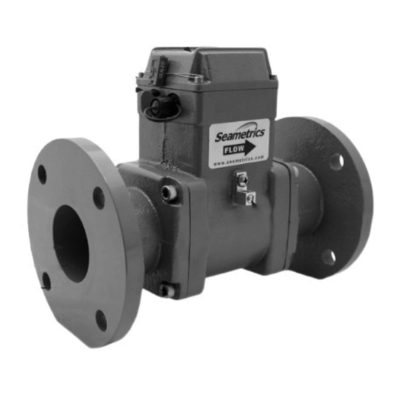
GENERAL INFORMATION FEATURES Continued Rate and total indicator Tamper-evident security seal & cross-drilled screws (2) for tamper-evidence Internal Data Logger (Optional) Power/Output cable port access, tamper-sealed (NOTE: WMX101 comes with standard 20’ cable installed) Powder-coated ductile cast iron body & electronics housing Glass filled molded plastic liner 316SS electrodes Flanges, ANSI 150 lb. -
Page 5: Specifications
>20 microSiemens/cm Empty Pipe Detection Hardware/software, conductivity-based Environmental NEMA 4X Standard (IP68 Option) Regulatory NSF-61 (3” ONLY) *Specifications subject to change. Please consult our website for the most current data (www.seametrics.com). FLOW RANGE (3” - 12”) Meter 3” 4” 6” 8”... -
Page 6: Installation And Grounding
INSTALLATION and GROUNDING INSTALLATION Installing Gaskets Caution: These flow sensors are not recommended GASKETS where installation fault may expose the flow sensor to Gaskets are required at all junctions. boiler pressure and temperature. Maximum (Not applicable to 3” model.) recommended temperature is 130˚ F. Positioning the Meter. - Page 7 INSTALLATION and GROUNDING Tightening Flange Bolts Equalization and Grounding NOTE: Mating pipe flanges must be ANSI 150# full face (FF) and/or raised face (RF). WARNING: ELECTRICAL SHOCK HAZARD When the is installed in a plastic piping system, or when externally powered, the 1.
-
Page 8: Straight Pipe Recommendations
STRAIGHT PIPE RECOMMENDATIONS (X = diameter) Reduced Pipe Two Elbows In Plane Two Elbows, Out Of Plane Expanded Pipe Swirling Flow Propeller Meter Swirling Flow Partially Open Butterfly Valve Page 6... -
Page 9: Full Pipe Recommendations
FULL PIPE RECOMMENDATIONS Recommended: Keep pipe full at meter for accuracy Not Ideal: Allows air pockets to form at meter Recommended: Not Ideal: Keeps pipe full at meter for accuracy Post-valve cavitation can create air pocket Recommended: Not Ideal: Allows air to bleed off Air can be trapped Intermittent air bubbles... -
Page 10: Inputs/Outputs And Operation
4-20 mA be changed in the field only by an authorized individual. signal conversion, datalogging, and telemetry applications. See page 7 for connection diagrams to Seametrics controls Refer to the diagrams below to read your display. and displays. -
Page 11: Connections Diagrams
CONNECTIONS DIAGRAMS (WMX101) WMX101 Cable Color Codes The WMX101 requires a power source of 8 to 32 Vdc at 30 mA max (see WARNING). The WMX101 power cable also Orange and Blue: Serial Output (Do Not Use) Green (+) and White (-): Pulse Output, 30 Vdc max, 10 mA max serves as a pulse output if needed for remote reading, data Red (+) and Black (-): External Power, 8-32 Vdc at 30 mA max logging, signal conversion, or telemetry. -
Page 12: Troubleshooting
Add pull-up resistor Meter reads, but no External device needs pull-up resistor (For details, refer to ‘Connecting to PLCs’ pulse output (WMX101) Technical Bulletin at www.seametrics.com) Reversed leads (polarity sensitive) Change output connections Meter not reading Output pulses missing Check display S eame tric s •...
Need help?
Do you have a question about the WMX SERIES and is the answer not in the manual?
Questions and answers