Seametrics AG3000 Series Instructions Manual
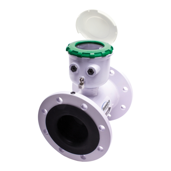
Irrigation magmeter
Hide thumbs
Also See for AG3000 Series:
- Mechanical quick start manual (2 pages) ,
- Instructions manual (20 pages) ,
- Quick start manual (2 pages)

Related Manuals for Seametrics AG3000 Series


Summary of Contents for Seametrics AG3000 Series
- Page 1 AG3000 Irrigation Magmeter Instructions PROUDLY MADE IN THE 9001 Free battery replacement at year five with warranty registration!
-
Page 2: Table Of Contents
Probable Cause................................Page 23 Things to Try ..................................Page 23 Error Messages ................................Page 23 Warranty Seametrics Limited Warranty ..........................Back Note: These instructions cover the AG3000. For details on the AG3000p or AG3000r, see the AG3000p & AG3000r Irrigation Magmeter Instructions. Seametrics • 253.872.0284 Page 2 seametrics.com... -
Page 3: General Information
Minimal straight pipe requirements allow AG3000 The AG3000 Series is CE certified and IP68 for burial, or meters to be used in piping configurations where there is applications where the meter may be under water for little space between the meter and an elbow. -
Page 4: Specifications
(lengths up to 200’ available). (AG3000r) Conductivity >20 microSiemens/cm Empty Pipe Detection Hardware/software, conductivity-based Regulatory (EN 61326) Environmental NEMA 6P, IP68 (10ft (3m) depth, continuously) Modbus is a registered trademark of Schneider Electric. * Specifications subject to change. Please consult our website for the most current data (www.seametrics.com). If forward and reverse flow data needs to be sent to another device, either the Digital or Modbus output is required. Rate Time Unit is available in Day only. Seametrics • 253.872.0284 Page 4 seametrics.com... -
Page 5: Dimensions
17.5 5.05 8” 14.24 10.1 17.5 6.44 10” 18.18 11.2 17.5 8.61 12” 19.68 12.2 20.6 10.55 Flanges Standard ANSI 150 lb. drilling Cable 1 lb. Install security seal during installation if regulations require. Seametrics • 253.872.0284 Page 5 seametrics.com... -
Page 6: Accuracy
5140 8031 11565 (Gallons/Minute) Cut-off (min) Flow 3.62 6.43 14.46 25.70 40.15 57.82 Rate (Gallons/Minute) Max Flow Rate (Liters/Second) Cut-off (min) Flow 0.23 0.41 0.91 1.62 2.54 3.65 Rate (Liters/Second) Max Flow Velocity (Meters/Second) Seametrics • 253.872.0284 Page 6 seametrics.com... -
Page 7: Straight Pipe Recommendations
AG3000 INSTRUCTIONS INSTALLATION Straight Pipe Recommendations (X = diameter) Reduced Pipe Two Elbows In Plane Two Elbows, Out Of Plane Expanded Pipe Swirling Flow: Propeller Meter Swirling Flow: Partially Open Butterfly Valve Seametrics • 253.872.0284 Page 7 seametrics.com... -
Page 8: Full Pipe Recommendations
Electrode moved from top by rotating meter Electrodes free from sediment AG3000 AG3000 build-up Best: Not Ideal: Improved accuracy results from If pipe contains air bubbles or sediment unimpeded electrodes (may affect accuracy) Seametrics • 253.872.0284 Page 8 seametrics.com... -
Page 9: Positioning The Meter
The meter must not be installed where it will be exposed debris. to extreme levels of vibration. 2. Install Seametrics provided gaskets, or equivilent, Using a check valve on the upstream side of the meter, on each end of meter as shown in diagrams below. -
Page 10: Tightening Flange Bolts
Grounding Ring Grounding Ring 3” Gaskets Gaskets 4” Plastic Plastic 6” Pipe Pipe 8” Ground Clamp (Exothermically weld when corrosion is a concern) 10” 12” Earth #6, #8, or #12 AWG Stranded Copper Ground Wire < 5’ 8’ Ground Rod Seametrics • 253.872.0284 Page 10 seametrics.com... -
Page 11: Connections
2-pin connectors may have one or two cable glands, depending on configuration.) Cable Gland Opening and Sealing WARNING: Improper sealing of glands or cables will invalidate any warranty. Remove plug & o-ring. Insert Clamp cable with strain relief CRITICAL! cable gland/strain relief. Feed clips. Attach drain wire lug to Torque cable gland sealing cable through cable gland. bracket post. nut to 22 in-lbs. Seametrics • 253.872.0284 Page 11 seametrics.com... -
Page 12: Cable Installation
7. If using the 15 pin screw connector, plug it into its socket. Be sure all pins align properly and that the connector has not slipped to one side. Improper alignment Proper alignment Battery Only Version with no external pulse output No wiring is needed. Seametrics • 253.872.0284 Page 12 seametrics.com... -
Page 13: Wiring Diagrams
Black (C1) DC-: pn14 Orange (C1) 4-20mA+: pn3 Orange (C1) 4-20mA+: pn3 Blue (C1) 4-20mA-: pn4 Blue (C1) 4-20mA-: pn4 DC Power with Pulse and 4-20mA (D1L/D2L) DC Power with Pulse and HART/4-20mA (D1H/D2H) Seametrics • 253.872.0284 Page 13 seametrics.com... - Page 14 15 Pin Connector for AG3000 DC Versions WARNING: BACKUP BATTERIES ARE NOT INTENDED AS A PRIMARY POWER SOURCE OF A MAINS (DC or AC) CONFIGURED Plug the backup battery METER. cable into the circuit board Seametrics • 253.872.0284 Page 14 seametrics.com...
-
Page 15: Cable Wiring Table
D1S/D2S = DC POWER / PULSE SCALED AND MODBUS ® D1G/D2G = DC POWER / PULSE SCALED AND DIGITAL Two 2-pin Connectors for AG3000 Battery Version 15 Pin Connector for AG3000 DC Versions Note that when viewing the connectors from the front of the meter, the labels will be upside down, as shown above, with numbering going from left to right. Seametrics • 253.872.0284 Page 15 seametrics.com... -
Page 16: Configuration
AG3000 INSTRUCTIONS Pulse Output Application - Sourcing Mode (Recommended for Rin < 30kΩ) Pulse Output Application - Sinking Mode (Recommended for Rin > 30kΩ) Analog (4-20mA Current Loop) Output Application ** Minimum resistor value is (100 x Vs) ohms. Higher resistances maybe used depending on frequency and cable length. Longer cables and high frequencies require lower resistance. *** Resistor RL converts 4-20mA current to voltage for voltage input only devices. Seametrics • 253.872.0284 Page 16 seametrics.com... -
Page 17: Cable Shield
500 seconds. period by 0.15 Width (ms) Pulse Timing in Battery Powered Units. The output pulse Example: If frequency = 20 Hz then the pulse period = 50 milliseconds and width in battery powered units is short and varies with pulse pulse width = (.05 x 50 milliseconds) = 2.5 ms frequency. (See table) Seametrics • 253.872.0284 Page 17 seametrics.com... -
Page 18: Analog (4-20Ma) Output
To change the Polling address, use AG3000 menu HPOLL to set the Polling address. settings to full-duplex RS232 or 3.3V CMOS (See Seametrics Modbus Interface Description manual for instructions). To get to this menu, move to the EXIT tab and tap the left The TXD connection is the transmitted data output from button 4 times. -
Page 19: Operation
EXIT system. (If you enter the wrong passcode, hold tab using the right button. and tap again to return to the previous screen. See page 21 for information on how to change a passcode.) To return to the HOME screen, perform the ENTER PASSCODE hold and tap sequence. 000000 HOLD TAP PRESS TO CHANGE Seametrics • 253.872.0284 Page 19 seametrics.com... -
Page 20: Changing Flow Meter Settings - Standard Menu Options
COMM MBID FL DIR INFO COMM MBID FL DIR PRESS TO VIEW INFO PRESS TO VIEW INFO ABOUT METER ABOUT METER S AMP HPOLL FOUT EXIT S AMP HPOLL S AMP FOUT EXIT Sub-Menu Sub-Menu - Battery Only Version Seametrics • 253.872.0284 Page 20 seametrics.com... -
Page 21: To Change A Passcode
15 minutes and cycling all S AMP FOUT EXIT power within this 15 minute time frame will return the meter to its previous total. Seametrics • 253.872.0284 Page 21 seametrics.com... -
Page 22: Power Indicators
DAMP is set to four, then when the meter begins to show a flow rate, the rate displayed is the average of all the NOTE: If a large percentage of the meter’s life will be spent readings taken in seconds one through five (4 plus 1). below 0.5 meters/second and above cutoff, battery life will be reduced. Seametrics • 253.872.0284 Page 22 seametrics.com... -
Page 23: Troubleshooting & Error Messages
Loop output = 22.8mA COMM FAIL Communication between transmitter and sensor board fails. Loop output = 22.8mA OVER RANGE Rate exceeds number of digits that can be displayed. Adjust units. Loop output = 4mA Seametrics • 253.872.0284 Page 23 seametrics.com... - Page 24 (5) years from date of shipment. Seametrics’ obligation under this warranty shall be limited to replacing or repairing the part or parts, or, at Seametrics’ option, the products, which prove defective in material or workmanship. The following are the terms of Seametrics’ limited warranty: Buyer must give Seametrics prompt notice of any defect or failure and satisfactory proof thereof.
Need help?
Do you have a question about the AG3000 Series and is the answer not in the manual?
Questions and answers