Table of Contents
Advertisement
Advertisement
Table of Contents

Summary of Contents for ROBBE Telemetry-Box
- Page 1 Instructions, Telemetry-Box 2.4 GHz FASSTest ® No. F1666...
-
Page 2: Table Of Contents
• The Telemetry-Box switches itself off automatically when the battery voltage falls to 3.3 V. If this should Mounting the Telemetry-Box on the transmitter 5 happen, you must still switch the Telemetry-Box off using the switch on the back of the unit. Switching the Telemetry-Box on ....... 6 Please check the battery voltage before every flight. -
Page 3: General Description
The Telemetry-Box can pick up the signals from any re- ceiver with integral telemetry transmitter. For example, from R7008SB and R6308SBT receivers. The Telemetry-Box is suitable both for upgrading existing FASST systems to telemetry (R6308SBT required at the model end), and also as a parallel display and output de- vice for callers and co-pilots in the case of FASSTest®... -
Page 4: Controls
Telemetry-Box 2.4 GHz FASSTest ® 5. CoNTrolS LCD screen with backlighting The Telemetry-Box features a range of facilities and con- nection options. These include a set of buttons for con- trolling the display, and for setting up and programming Buzzer / loudspeaker sensors. "ESC" button "eSC"... -
Page 5: Mounting The Telemetry-Box On The Transmitter
This is the procedure: This is the procedure: • Screw the adapter to the threaded part of the aerial. • Remove the two screws in the adapter, and separate the two components. • Adjust the position of the adapter so that the "robbe" label is legible. • Place the front and rear sections round the carry handle, and re-assemble them. • If you wish to make fine adjustments, loosen the screw on the back of the adapter. Adjust the adapter's position, • Now adjust the position of the adapter so that you can... -
Page 6: Switching The Telemetry-Box On
7. SwITCHING THe TeleMeTry-Box oN 8. CHArGING THe TeleMeTry-Box To switch the unit on, the micro-switch on the back of the The Telemetry-Box is fitted with an internal 3.7 V / 500 unit must be moved up to the "ON" position. mAh LiPo battery. The Telemetry-Box battery can be char- ged from any PC or USB charger using the mini-USB lead. -
Page 7: Binding The Telemetry-Box To The Transmitter
When you switch models, this makes it possible to con- • Ensure that the receiver in the model is bound to the To ensure that the Telemetry-Box can pick up data from the RC system transmitter. tinue to use the Telemetry-Box without having to re-bind. receiver, the receiver must first be bound to the transmitter. • Place the RC system receiver close to the Telemetry- The method of binding is described in the instructions sup- Box (approx. -
Page 8: Menu Structure / Description Of Navigation
Telemetry-Box 2.4 GHz FASSTest ® 10. MeNu STruCTure / DeSCrIPTIoN oF NAvIGATIoN PAUSE TIME 10 S S p e e c h S c r e e n A:ACT MODEL0 SPH/ ON A:ON MODEL0 SPH/ ON RECEIVER-BATTERY REPEAT RECEIVER-BATTERY o u t p u t... -
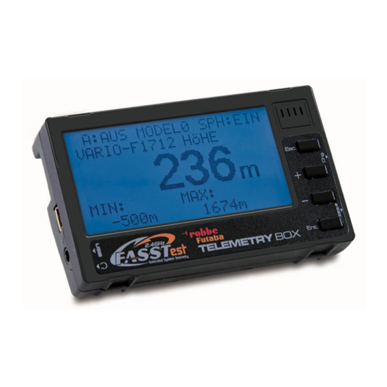
Page 9: Explanation, Telemetry Display
Telemetry-Box 2.4 GHz FASSTest ® 11. exPlANATIoN, TeleMeTry DISPlAy In its basic form the telemetry display is always the same; it varies only according to the various sensors in use. The "+" and "-" buttons are used to navigate through the Display menu, as described in chapter 5. -
Page 10: Explanation, Speech Output Display
Telemetry-Box 2.4 GHz FASSTest ® 12. exPlANATIoN, SPeeCH ouTPuT DISPlAy 13. exPlANATIoN, voluMe DISPlAy In the Speech Output display you can set which sensor The volume of the speech output can be adjusted in the data are to be generated in speech output form. -
Page 11: Programming Menu, Main Display
Telemetry-Box 2.4 GHz FASSTest ® 14.2 DISPlAy MeNu 14. MAIN SCreeN ProGrAMMING MeNu 14.1 SPeeCH MeNu Holding both the "+" and "-" buttons pressed in takes you In the "Display" menu you can adjust the parameters for In the "Speech" menu the parameters for speech output from the Display menu to the Programming menu. -
Page 12: Sensor Setup Menu
Telemetry-Box 2.4 GHz FASSTest ® DISPlAy: 14.3 SeNSor SeTuP MeNu explanation, "Sensor Setup" sub-menu At the "Display" setting it is possible to program whether The "Sensor Setup" menu shows all registered sensors. It To move to the set-up sub-menu of a sensor, use the "-"... - Page 13 Telemetry-Box 2.4 GHz FASSTest ® wArNINGToNe: >WARN DuRATION: Here you can select a sound which provides an audible REPEATTIME: warning that the MIN VALUE has been reached. Adjustment range: 0 ... 29 FACTORY SET: MAx vAlue: At this point it is possible to select a maximum value, which triggers an on-screen warning, the vibration alarm and an audio alarm when it is reached.
-
Page 14: Sensor Register Menu
Telemetry-Box 2.4 GHz FASSTest ® The following screen display now appears: 14.4 SeNSor reGISTer MeNu registering a sensor TYPE: VARIO The "Sensor Register" menu is used to register new sen- • Connect a sensor to the S-BUS2, taking care to maintain sors to the system, and to display sensors which are alrea- >NuMBER:... -
Page 15: Model Select Menu
Telemetry-Box 2.4 GHz FASSTest ® explanation, "oPeN MoDel" sub-menu explanation, "erASe model" sub-menu 14.5 MoDel SeleCT MeNu Data for up to ten different models can be stored in the When you open the menu, the screen display looks When you open the menu, the screen display looks "Model Select" menu; they can then be activated when you... -
Page 16: Language Select Menu
15. uSB PC SoCkeT The screen language is selected in the "LanguageSE- This is the procedure for selecting a language: The Telemetry-Box is fitted with a mini-USB port on the LECT" menu. left-hand side. The mini-USB lead can be plugged into • Move to the "Language Select" menu. -
Page 17: Recommended Accessories
No. F1672 26 mm No. F1666100 Precision variometer with altitude Adapter mounting and variometer monitoring using Telemetry-Box on the FC-18 trans- two separate pressure sensors. mitter. Gooseneck for Telemetry- GPS Multi Sensor No. F1675 No. F1666200 Multi-functional GPS vario / alti-... -
Page 18: Usb Driver Installation For Telemetry-Box
17. uSB DrIver INSTAllATIoN For THe TeleMeTry-Box Note: Note: The uSB driver must be installed for the purpose of carrying out a software or speech update. The uSB driver, and the "robbe_Telemetry_Downloader" update program, can be found on the robbe website at: http://www.robbe.de/telemetry-box-2-4-ghz-fasstestr.html 3. Click on "NEXT". - Page 19 Telemetry-Box 2.4 GHz FASSTest ® 5. This completes the driver installation. Select the "Launch the CP210x VCP Driver Installer" field and click on "FINISH". 6. Click on "INSTALL". When the installation is complete, confirm with "OK".
-
Page 20: Robbe Telemetry-Box Update
2. Start the file "Robbe_Telemetry_Downloader_V1.1". The following display appears. 5. The various displays appear as follows: 3. Select "Port Select-Telemetry-Box" under "Config" in order to define the port on the PC to Firmware update display which the Telemetry-Box is connected. - Page 21 It is essential not to disconnect or switch off the device during the update procedure. In the worst case this could ruin the device. 7. Close the field once the installation is successfully completed. 8. After installation, switch the Telemetry-Box off and remove the USB lead. The new software can now be used.
-
Page 22: Service Centre Addresses
Telemetry-Box 2.4 GHz FASSTest ® 19. ServICe CeNTre ADDreSSeS Country Company Street City Telephone e-mail AND-00130 Les escaldes- Andorra Sorteny Santa Anna, 13 00376-862 865 00376-825 476 sorteny@sorteny.com Princip. D‘Andorre Denmark Nordic Hobby A/S Bogensevej 13 DK-8940 Randers SV 0045-86-43 61 00 0045-86-43 77 44 hobby@nordichobby.com... -
Page 23: Guarantee
/ battery-powered product from us. The battery of those robbe products directly involved in the event in lasts a very long time, but at some time you will We accept no liability for transport damage, nor for the which the damage occurred, unless otherwise prescribed need to dispose of it. -
Page 24: Conformity Declaration
Errors and technical modifications reserved. D-36355 Grebenhain OT Metzlos/Gehaag Copyright robbe-Modellsport 2012 robbe Form AHBC Duplication and copying of the text, in whole or in part, www.robbe.com is only permitted with the prior written approval of robbe- hotline@robbe.com Modellsport GmbH & Co. KG...
Need help?
Do you have a question about the Telemetry-Box and is the answer not in the manual?
Questions and answers