
Subscribe to Our Youtube Channel
Related Manuals for Mecmesin MultiTest 1-dV


Summary of Contents for Mecmesin MultiTest 1-dV
- Page 1 MultiTest-dV Tension and Compression Test Stand Operating Manual 431-459-04 February 2019...
- Page 2 For operating in conjunction with Vector Pro™, see the manual 431-955, VectorPro™ for Mecmesin Test Stands and Instruments. 2018 © Mecmesin Ltd, supplied with Mecmesin test systems and not for redistribution Part no. 431-459-04 2 Mecmesin...
-
Page 3: Table Of Contents
Cable Management 4.12. Attaching Grips and Fixtures 4.13. Setting the Limit Stops 4.14. Test Stand States Front Panel Controls Emergency Stop Button Multi-function Scroll Wheel Control MultiTest-dV Display Panel On-Screen Icons Automatic ELS Firmware Update Mecmesin 3 MultiTest-dV Operating Manual... - Page 4 3.0.7 - New Features 3.0.7 - Bug Fixes 3.0.8 - New Features 3.0.8 - Bug Fixes 3.0.10 - New Features 3.0.10 - Bug Fixes 13. Test Stand Firmware/ Software Compatibility Table 14. Operator Notes 4 Mecmesin MultiTest-dV Operating Manual...
-
Page 5: Items Supplied With The Test Stand
Mecmesin website www.mecmesin.com, or your local distributor, as listed on the back cover. For connection of the stand to your computer, a Mecmesin supplied 2m USB B to USB A cable communications cable is required (part no. 351-093), ... -
Page 6: Multitest-Dv System Diagram
2. MultiTest-dV System Diagram Upper and lower safety limit switches are located on the rear of the column Dovetail crosshead ELS Socket Front control panel Multi-function scroll wheel Emergency stop 6 Mecmesin MultiTest-dV Operating Manual... -
Page 7: Multitest-Dv - Dual Functionality
By default all MultiTest-dV test stands are supplied in dV mode, to switch the test stand to dV(u) mode both VectorPro and a dV(u) license key are required, these can both be ordered separately from your local Mecmesin distributor. 3.1. Identifying a Mark 2 MultiTest-dV... -
Page 8: Functionality Differences
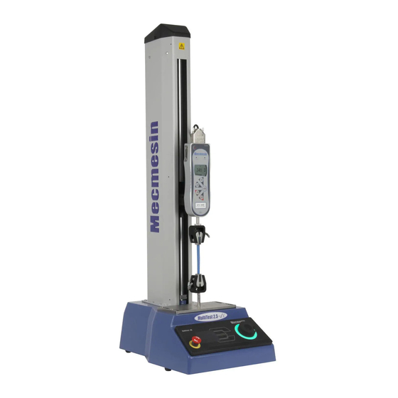
Single operation VectorPro Force limit control SDC support Suitable for basic product testing Suitable for basic material testing A MultiTest-dV 2.5kN in dV(u) mode performing a 3-point bend, using an ELS 500N and deflectometer 8 Mecmesin MultiTest-dV Operating Manual... -
Page 9: Switching Dv Modes
3.0.2 or later and VectorPro 5.1.0.0 or later. The dV(u) key is a separate accessory and can be purchased from your local Mecmesin agent. The key is linked to an individual test stand. It is crucial when ordering the key that you supply the test stand’s serial number. -
Page 10: License Keys
A VectorPro Lite license key is required to run dV tests within VectorPro, this key is not required when testing in dV(u) mode but you do require a dV(u) key to switch the stand from dV mode to dV(u) mode. 10 Mecmesin MultiTest-dV Operating Manual... -
Page 11: Initial Setup
Do not try to lift heavy loads unaided. 4.3. Environment Conditions In line with BS EN 61010-1 it is recommended that your Mecmesin MultiTest-dV test stand is operated in an environment that matches the following conditions: Indoor use only. Recommended to be operated in a lab environment. -
Page 12: Mains Power Supply
MultiTest-dV test stands use two 2A - Speed T, 5 x 20mm fuses. If replacing a blown fuse, replace only the fuse on the active side of the inlet filter with the fuse specified above, or equivalent. If you are in doubt, please contact your local Mecmesin support agent for more information. 12 Mecmesin... -
Page 13: Fitting The Feet To The Stand
For MultiTest-dV, 0.5kN and 1.0kN test stands it is recommended that the system is mounted to a suitable work surface using the supplied bench mount adapters. Please see the next section for more information. Mecmesin 13 MultiTest-dV Operating Manual... -
Page 14: Bolting The Test Stand To The Work Surface
Anchor brackets Rubber feet The extended-length test stands (MultiTest 0.5-dV and MultiTest 1-dV) are supplied with base anchoring brackets to allow the test stands to be bolted to a bench. Screw the anchoring brackets to the four positions on the base plate of the MultiTest 0.5- dV or 1-dV using the M6 screws provided (Shown below). -
Page 15: Fitting And Connecting An Afg
To fit an AFG first, attach the AFG mounting bracket (part no. 432-427) to the back of a Mecmesin AFG or AFTI digital force gauge. Then slide the gauge sideways onto the dovetail and secure it by tightening the dovetail screw with an Allen key. -
Page 16: Connecting An Afg To The Multitest-Dv
Connecting an AFG to the MultiTest-dV A Mecmesin AFG digital force gauge is connected to the test stand using cable part no. 351-092. Connect the 15-pin D connector to the top socket of the AFG, and the opposite end of the cable to the RJ11 plug located on the rear of the stand:... - Page 17 12. Then press twice to return to the primary measurement screen. Note: If using the stand in conjunction with VectorPro please ensure that the units selected on the gauge match the unit selected within the software. Mecmesin 17 MultiTest-dV Operating Manual...
-
Page 18: Els - Enhanced Load Sensor
See the MultiTest-dV Specification of this document for details relating to capture rate and accuracy. A selection of enhanced load sensors (Not all ELS devices shown are compatible with MultiTest-dV test stands) 18 Mecmesin MultiTest-dV Operating Manual... -
Page 19: Fitting An Els To A Test Stand
4.10. Fitting an ELS to a Test stand MultiTest-dV test stands with dV(u) mode enabled use Mecmesin ELS devices to capture load readings. To fit an ELS to the test stand slide the load cell sideways onto the dovetail and tighten the grub screw (circled below in red) located in the dovetail using a suitable Allen key. -
Page 20: Connecting An Els To The Multitest-Dv
Cable Management It is essential that no cables interfere with the controls or any moving parts. Failure to do so could lead to injury or damage to the equipment. 20 Mecmesin MultiTest-dV Operating Manual... -
Page 21: Attaching Grips And Fixtures
Anvil plate located at the base of the MultiTest-dV Upper grips and accessories are attached directly to the ELS device being used. QC adapters are available and can be fitted directly to the anvil plate or through a Mecmesin LTE-700 extensometer. Mecmesin 21 MultiTest-dV Operating Manual... -
Page 22: Setting The Limit Stops
4. Jog mode - for jogging or positioning the crosshead manually, 5. Settings menu – for adjusting your test stands settings, In each state, the selector buttons have functions described by the on-screen icons. 22 Mecmesin MultiTest-dV Operating Manual... -
Page 23: Front Panel Controls
The lights surrounding the wheel illuminate in three colours, indicating the status of the test stand: Green Light Amber Light Red Light Pulsating: Ready to start test Static: Test completed Static: Test stopped/limit Rotating: Scrolling through a Rotating: Crosshead moving triggered menu Mecmesin 23 MultiTest-dV Operating Manual... - Page 24 The central button is used to confirm a menu selection. It is equivalent to the tick button. It can also be used to activate fine jog control, rotating the scroll wheel while holding the central button in jog mode moves the test stand at its minimum speed. 24 Mecmesin MultiTest-dV Operating Manual...
-
Page 25: Multitest-Dv Display Panel
1. Test Readiness Icon Action No AFG connected / No ELS connected (if in dV(u) mode). Start the test sequence. Go to jog mode. Go to settings. Mecmesin 25 MultiTest-dV Operating Manual... - Page 26 Move to the home position (start position from the beginning of the previous test). This icon is only visible after pressing the stop Exit to the test ready screen, leaving the crosshead in its current position. 26 Mecmesin MultiTest-dV Operating Manual...
- Page 27 Confirm selection (or press the scroll wheel button). Navigate up a menu selection or value (or turn the wheel clockwise). Navigate down a menu selection or value (or turn the wheel anticlockwise). Go back to the previous screen. Mecmesin 27 MultiTest-dV Operating Manual...
-
Page 28: Automatic Els Firmware Update
The new ‘Stored’ firmware is listed at the top of the display and the current ELS firmware is displayed below. In this instance the current firmware for the ELS is 1.0.4.7, starting the update will flash the device to version 1.0.6.1. 28 Mecmesin MultiTest-dV Operating Manual... -
Page 29: Step 3 - Flashing The Device
In the image above initial programming is taking place. You can monitor the progress using the bar and percentage readout shown onscreen. Within the final stage of the process, the firmware upgrade is verified to check that is has completed successfully. Mecmesin 29 MultiTest-dV Operating Manual... - Page 30 ELS devices are connected. You can check the version of the ELS firmware manually by accessing the ‘Information’ screen located in the ‘Settings’ menu, See Section 6 for more information. 30 Mecmesin MultiTest-dV Operating Manual...
-
Page 31: Multitest-Dv Settings
Configure the compressive force limit while in jog mode 0 to -200 N Configure whether or not the AFG/AFTI is tared when Tare AFG/AFTI Yes or No pressing the tare button in jog mode. Mecmesin 31 MultiTest-dV Operating Manual... -
Page 32: Settings: Units
A positive displacement is above tared zero and a negative value is Upper Displacement below. Available displacement depends on the test setup. A positive displacement is above tared zero and a negative value is Lower Displacement below. 32 Mecmesin MultiTest-dV Operating Manual... - Page 33 Configured using the front panel. Cycle between a limit force and a return force. Configured using Force Cycle the front panel. Move in the configured direction until a break condition is detected. Break Configured using the front panel. Mecmesin 33 MultiTest-dV Operating Manual...
- Page 34 AFG Control Test With an additional cable (351-092), a Mecmesin AFG digital force gauge can be used to set load limits to control crosshead movement. Load setpoint, action (reverse/stop) are all set on the gauge under the ‘STAND’ menu. Here you can select the action when the limit is reached; ‘REVERSE’ or ‘STOP’ and the type of control limit ‘BREAK’...
- Page 35 Test Sub-Type: Force Limit Limit Force: 50 N The crosshead moves down at 100 mm/min until the applied load is 50 N from tared zero, once the limit force is reached the test stops. Mecmesin 35 MultiTest-dV Operating Manual...
- Page 36 Please note the speed and test direction use the settings configured within VectorPro, while other test settings are loaded from the front panel. For more information please refer to the VectorPro user manual, part no. 431-955. 36 Mecmesin MultiTest-dV Operating Manual...
- Page 37 4. Set the desired start direction and whether to move to start, 5. Configure the number of cycles, 6. Execute the test. The stand moves between the two displacements for the configured number of cycles and then stop. Mecmesin 37 MultiTest-dV Operating Manual...
- Page 38 Lower displacement: Down Initial stroke: Move to Start: Unless already at 30 mm above tared zero, the crosshead will travel to that point and then move to 20 mm below tared zero, and stop. 38 Mecmesin MultiTest-dV Operating Manual...
-
Page 39: Settings: Pin Code
PIN, so it is crucial that you keep a record of this safe. If the PIN code has been set and then lost or is unknown, please contact your local agent or Mecmesin Technical Support. Settings: Languages Select your desired language. -
Page 40: Multitest-Dv Settings - Dv(U) Operation
PIN, so it is crucial that you keep a record of this safe. If the PIN code has been set and then lost or is unknown, please contact your local agent or Mecmesin Technical Support. Settings: Information This screen is used to display vital information relating to your MultiTest-dV and connected devices. -
Page 41: Rear Connectors Panel
8. Rear Connectors Panel Inlet mains filter and on/off switch RJ11 port for AFG digital force gauge USB-B Comms port System vent. Do not obstruct! Digital IO port (Not currently implemented) Extensometer port Mecmesin 41 MultiTest-dV Operating Manual... -
Page 42: Multitest-Dv Specification
Stand Via USB (VectorPro™ Software - PDF, XLXS, CSV, TXT, Email and Images) Output of Test Results AFG / AFTI Via Cable (sales@mecmesin.com) Measured with force gauge and short extension rod fitted Measured on centreline of gauge/sensor † Where mains voltage is reliable ††... -
Page 43: Multitest-Dv Dimensions
10. MultiTest-dV Dimensions MultiTest-dV 2.5kN Dimensions Note: The above drawing is not to scale! Mecmesin 43 MultiTest-dV Operating Manual... -
Page 44: Multitest-Dv 1.0Kn Dimensions
MultiTest-dV 1.0kN Dimensions Note: The above drawing is not to scale! 44 Mecmesin MultiTest-dV Operating Manual... -
Page 45: Multitest-Dv 0.5Kn Dimensions
MultiTest-dV 0.5kN Dimensions Note: The above drawing is not to scale! Mecmesin 45 MultiTest-dV Operating Manual... -
Page 46: Declaration Of Conformity
11. Declaration of Conformity 46 Mecmesin MultiTest-dV Operating Manual... -
Page 47: Change Log
Major Feature! AFG/AFTI stand control force limits now also work in jog mode, this can be used to protect damage to the system while jogging, Mecmesin 47 MultiTest-dV Operating Manual... -
Page 48: Bug Fixes
Fixed issue where the AFG wasn’t tared correctly, Fixed issue where an extensometer could create an overload that would terminate the test, Test not being terminated by over temperature reading has now been fixed, 48 Mecmesin MultiTest-dV Operating Manual... -
Page 49: New Features
3.0.10 - Bug Fixes Fixes Stop/Reverse function being ignored if AFG is not seen as connected Fix speed settings not updating in edit test menus Fix Load readings frozen in Move to Break test Mecmesin 49 MultiTest-dV Operating Manual... -
Page 50: Test Stand Firmware/ Software Compatibility Table
Please note the stand must a MultiTest-dV Mark 2 with a serial number after 17-1XXX-11 to operate in dV(u) mode 50 Mecmesin MultiTest-dV Operating Manual... -
Page 51: Operator Notes
14. Operator Notes Mecmesin 51 MultiTest-dV Operating Manual... - Page 52 Mecmesin : a world leader in affordable force and torque testing solutions Since 1977, Mecmesin has assisted thousands of companies achieve enhanced quality control in design and production. The Mecmesin brand represents excellence in accuracy, build, service, and value. In production centres and research labs worldwide, designers, engineers, operators, and quality managers endorse Mecmesin force and torque testing systems for their high performance across countless applications.
Need help?
Do you have a question about the MultiTest 1-dV and is the answer not in the manual?
Questions and answers