
Related Manuals for Mecmesin MultiTest–i Series


Summary of Contents for Mecmesin MultiTest–i Series
- Page 1 Assembly and Installation of MultiTest–i and Vortex-i System Test Stands 431-393-07 December 2018...
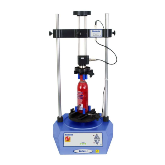
- Page 2 Torque testing stand Vortex–i Torque cell capacities: 0.3, 1.5, 3, 6, 10 Nm 2016 © Mecmesin Ltd, supplied with Mecmesin test systems and not for redistribution Part no. 431-393-07 ii Mecmesin Assembly and Installation of –i System Test Stands...
-
Page 3: Table Of Contents
Connecting the power lead and USB lead Emergency stop button Jog buttons Installing Emperor Software on Your PC Minimum system requirements Access to data folders Start Emperor System Specifications EC Declaration of Conformance Mecmesin iii Assembly and Installation of –i System Test Stands... - Page 4 Mecmesin Assembly and Installation of –i System Test Stands...
-
Page 5: Items Supplied With The Test Stand
5. At least one Intelligent Loadcell (ILC) 6. CD with Emperor™ software 7. Mains and data cables 8. Manual: Guide to Safe Use of Mecmesin Mains-Powered Test Stands 1.2 Vortex-i test stand 1. Test stand 2. Intelligent Torque Cell (ITC), as an integral part of the crosshead 3. -
Page 6: Installation
The test stand should be positioned on a suitable, level, stable work surface. 2.4 Mains power supply Mecmesin –i stands can be used on 110–120 or 220–240 V ac 50-60 Hz supplies. The rear fuse carrier will be set for your local requirement, but is reversible, so should you replace a fuse, the correct local voltage must be selected. -
Page 7: Multitest-I Assembly And Installation
For additional stability the MultiTest 5-i is fitted with two ‘locating eyes’ on the base of the MultiTest 5-i to allow the stand to be bolted to a bench. Mecmesin twin-column force testing stands and Vortex torque testing stands require no further stability fixing than a flat, secure and stable working surface. -
Page 8: Fitting The Feet To The Stand
Release and turn, and repeat as required. Do not tighten the lever without a loadcell attached, or the dovetail can become distorted. 4 Mecmesin Assembly and Installation of –i System Test Stands... - Page 9 The ILC is attached to a twin-column test stand using a cap-head bolt passed through the central hole in the moving crosshead, and secured using the Allen key provided. Attaching a loadcell on a twin-column system Mecmesin 5 Assembly and Installation of –i System Test Stands...
-
Page 10: Swapping Loadcells
To set either limit stop, slacken the knurled knob by turning it anti-clockwise, then slide the stop to the desired position and re-tighten the knob again. 6 Mecmesin Assembly and Installation of –i System Test Stands... - Page 11 In an emergency, to release a trapped sample the system limit can be moved, but if you do so, you must contact your Mecmesin distributor for servicing and re-setting. These stops are designed for protection from damage, and moving them may affect your warranty on the stand.
-
Page 12: Limits After Connection To The Pc, With The Software Running
Clicking will disconnect the stand and display the following message: Abort Click then to go to the Front Screen, this will reconnect the stand again. Exit 8 Mecmesin Assembly and Installation of –i System Test Stands... -
Page 13: Vortex-I Assembly And Installation
Align the electrical connector of the ITC with the mating socket on the test stand. Gently push the connector to locate then tighten the knurled locking ring in a clockwise direction. Mecmesin 9 Assembly and Installation of –i System Test Stands... -
Page 14: Swapping Intelligent Torque Cells
Emperor will read in the new cell’s range, serial number and calibration status. 10 Mecmesin Assembly and Installation of –i System Test Stands... -
Page 15: Connecting The Pc (Multitest-I And Vortex-I)
30 degrees clockwise. Emergency stop Jog buttons The front panel of the MultiTest 1-i. Vortex-i has a similar emergency stop button and clockwise and anticlockwise jog buttons. Mecmesin 11 Assembly and Installation of –i System Test Stands... -
Page 16: Jog Buttons
Emperor allows you to set either a fixed or variable rate. A variable rate means the jog speed increments (gets faster) or decrements (gets slower) each time an on-screen jog button is clicked. 12 Mecmesin Assembly and Installation of –i System Test Stands... -
Page 17: Installing Emperor Software On Your Pc
IT department to allow correct access to these locations. Windows XP User Data location Emperor Force C:\Documents and Settings\All Users\Application Data\Mecmesin\Emperor\Force Emperor Torque C:\Documents and Settings\All Users\Application Data\Mecmesin\Emperor\Torque Windows Vista or Windows 7 User Data location... -
Page 18: Start Emperor
For full details, see the manual: Emperor Programming for Mecmesin Test Systems. 14 Mecmesin Assembly and Installation of –i System Test Stands... -
Page 19: System Specifications
— — (2.6”) (2.6”) (2.6”) (3.7’) Vertical daylight†† 1359 mm 1159 mm 580 mm 675 mm 1140 mm 1140 mm 1330 mm (53.5”) (45.6’) (23.2’) (26.6’) (44.9’) (44.9’) (52.4’) Mecmesin 15 Assembly and Installation of –i System Test Stands... - Page 20 RS232 via USB/network converter in ASCII format Communication with PLC/Digital Control Interface Yes, via programmable digital ports 6 inputs + 6 outputs Options available on request: Column gaiter Safety guard 16 Mecmesin Assembly and Installation of –i System Test Stands...
- Page 21 Max power requirements 100 W Voltage 230 V AC 50 Hz or 110 V AC 60 Hz Loadcell calibration temperature 20±2°C * With upper and lower mounting tables fitted Mecmesin 17 Assembly and Installation of –i System Test Stands...
- Page 22 Communication with PLC/Digital Control Interface Yes, via programmable digital ports 6 inputs + 6 outputs Options available on request: Safety guard Mecmesin reserves the right to alter equipment specifications without prior notice. E&OE 18 Mecmesin Assembly and Installation of –i System Test Stands...
-
Page 23: Ec Declaration Of Conformance
EC Declaration of Conformance Mecmesin 19 Assembly and Installation of –i System Test Stands... - Page 24 Mecmesin : a world leader in affordable force and torque testing solutions Since 1977, Mecmesin has assisted thousands of companies achieve enhanced quality control in design and production. The Mecmesin brand represents excellence in accuracy, build, service, and value. In production centres and research labs worldwide, designers, engineers, operators, and quality managers endorse Mecmesin force and torque testing systems for their high performance across countless applications.
Need help?
Do you have a question about the MultiTest–i Series and is the answer not in the manual?
Questions and answers