Table of Contents
Advertisement
Quick Links
Advertisement
Table of Contents
Troubleshooting

Related Manuals for Acer Altos R520 M2 Series


Summary of Contents for Acer Altos R520 M2 Series
- Page 1 Acer Altos R520 M2 Series User’s Guide...
- Page 2 Copyright © 2009 All Rights Reserved. Acer Altos R520 M2 Series User’s Guide Model Name : Acer Altos R520 M2 Part Number: Purchase Date: Place of Purchase:...
- Page 3 Information for your safety and comfort Visit http://registration.acer.com and discover the benefits of being an Acer customer. Safety instructions Read these instructions carefully. Keep this document for future reference. Follow all warnings and instructions marked on the product. Turning the product off before cleaning Unplug this product from the wall outlet before cleaning.
- Page 4 • Slots and openings are provided for ventilation to ensure reliable operation of the product and to protect it from overheating. These openings must not be blocked or covered. The openings should never be blocked by placing the product on a bed, sofa, rug or other similar surface. This product should never be placed near or over a radiator or heat register, or in a built-in installation unless proper ventilation is provided.
- Page 5 Note: The grounding pin also provides good protection from unexpected noise produced by other nearby electrical devices that may interfere with the performance of this product. • Use the product only with the supplied power supply cord set. If you need to replace the power cord set, make sure that the new power cord meets the following requirements: detachable type, UL listed/CSA certified, VDE approved or its equivalent, 4.6 meters (15 feet) maximum length.
- Page 6 To minimize pollution and ensure utmost protection of the global environment, please recycle. For more information on the Waste from Electrical and Electronics Equipment (WEEE) regulations, visit http://www.acer-group.com/public/Sustainability/sustainability01.htm. Mercury advisory For projectors or electronic products containing an LCD/CRT monitor or display: Lamp(s) inside this product contain mercury and must be recycled or disposed of according to local, state or federal laws.
- Page 7 Tips and information for comfortable use Computer users may complain of eyestrain and headaches after prolonged use. Users are also at risk of physical injury after long hours of working in front of a computer. Long work periods, bad posture, poor work habits, stress, inadequate working conditions, personal health and other factors greatly increase the risk of physical injury.
- Page 8 viii Taking care of your vision Long viewing hours, wearing incorrect glasses or contact lenses, glare, excessive room lighting, poorly focused screens, very small typefaces and low-contrast displays could stress your eyes. The following sections provide suggestions on how to reduce eyestrain. Eyes •...
- Page 9 Developing good work habits Develop the following work habits to make your computer use more relaxing and productive: • Take short breaks regularly and often. • Perform some stretching exercises. • Breathe fresh air as often as possible. • Exercise regularly and maintain a healthy body. Warning! We do not recommend using the computer on a couch or bed.
- Page 10 Regulations and safety notices Declaration of Conformity for EU countries Hereby, Acer, declares that this PC series is in compliance with the essential requirements and other relevant provisions of Directive 1999/5/EC. Compliant with Russian regulatory certification List of applicable countries...
- Page 11 General This product complies with the radio frequency and safety standards of any country or region in which it has been approved for wireless use. Depending on configurations, this product may or may not contain wireless radio devices (such as wireless LAN and/or Bluetooth modules). Below information is for products with such devices.
- Page 12 Declaration of Conformity Acer Computer (Shanghai) Limited 8F, 88, Sec.1, Hsin Tai Wu Rd., Hsichih, Taipei Hsien 221, Taiwan Contact Person: Mr. Easy Lai Tel: 886-2-8691-3089 Fax: 886-2-8691-3120 E-mail: easy_lai@acer.com.tw Hereby declare that: Product: Server Trade Name: Acer Model Number:...
- Page 13 EN300 440-2 V1.1.2 (Applicable to non-bluetooth wireless keyboard mouse set) • EN300 328 V1.7.1 • EN301 893 V1.4.1 (Applicable to 5GHz high performance RLAN) Year to begin affixing CE marking 2009. April 9, 2009 Date Easy Lai, Manager Regulation Center, Acer Inc.
-
Page 15: Table Of Contents
Information for your safety and comfort Safety instructions Additional safety information Disposal instructions Mercury advisory Tips and information for comfortable use Regulations and safety notices Declaration of Conformity for EU countries List of applicable countries Laser compliance statement Radio device regulatory notice General European Union (EU) 1 System tour... - Page 16 3 System upgrade Installation precautions ESD precautions Pre-installation instructions Post-installation instructions Opening the server Removing and installing the front bezel Removing and installing the top cover Removing and installing the air duct Configuring the storage devices Removing and installing a hard disk drive Installing and removing an optical drive Replacing a dual-rotor fan module Fan cable connectors...
- Page 17 xvii Console Redirection Event Log Configuration Boot menu Exit menu 5 System troubleshooting Resetting the system Initial system startup problems Initial troubleshooting checklist Hardware diagnostic testing Checking the boot-up status Verifying the condition of the storage devices Confirming loading of the operating system Specific problems and corrective actions Appendix A: Server management tools Server management overview...
- Page 18 xviii Server Health Configuration Remote Control Maintenance Logout KVM Remote Console utility Menu bar Video Keyboard Mouse Option Device Help Index...
-
Page 19: System Tour
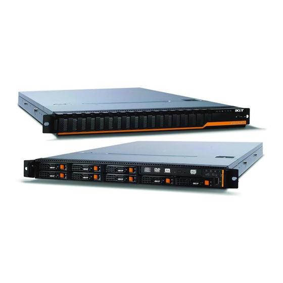
1 System tour... - Page 20 This chapter provides a brief overview of the system hardware, including illustrations with component identification.
-
Page 21: System Features
System features Listed below are the key features of the Acer Altos R520 M2 server. Performance Processor ® • One or two Intel Xeon™ processors 5500 series • 256 KB/per core L2 cache • 4 (dual-core) / 8 (quad-core) MB L3 shared cache •... - Page 22 1 System tour • Supports ECC, memory mirroring, lockstep mode PCI interface • Full height riser slot ® • One PCI Express 2.0 x16 slot (PCI Express 2.0 x16 throughput) (Max length: 167.65 mm) • Low profile riser slot • One PCI Express 2.0 x8 slot (PCI Express 2.0 x8 throughput) (Max length: 134 mm) Video controller...
- Page 23 Supports KVM-over-IP • USB mouse, keyboard, and media redirection • Acer EasyBuild™ v9.0 • Acer Server Manager (ASM) Media storage • Slim DVD writer • Supports up to eight 2.5-inch hot-plug SAS/SATA hard disk drives 2 Reserved for remote management of server.
-
Page 24: Mechanical
1 System tour Power supply and cooling system • 650-watts 1+1 (80% power efficiency) power supply, AC input operating voltages 100~127 VAC and 200-240 VAC, frequency 50/60 Hz (can be upgraded with second power module for hot- swap and redundancy) •... -
Page 25: Environmental
Environmental • Temperature • Operating: +0° to +40°C +0° to +30°C (when SAS RAID cards are installed) • Non-operating: +20° to +70°C • Humidity, non-operating : 90%, non-condensing @ 35°C... -
Page 26: External And Internal Structure
1 System tour External and internal structure Front bezel Icon Component LAN1 activity indicator LAN2 activity indicator HDD activity indicator Sysrem status indicator System ID indicator Power status indicator Security keylock This lock on the front bezel prevents unauthorized access for maximum security. -
Page 27: Front Panel
Front panel Icon Component Rack handles Slim optical drive Optical drive status indicator Optical drive eject button Power status indicator/ button System ID indicator/button LAN1 status indicator LAN2 status indicator Hard disk drive (HDD) activity indicator System status indicator... - Page 28 1 System tour Icon Component Non-maskable interrupt (NMI) button Puts the server in a halt-state for diagnostic purposes and allows the service technician to generate a NMI to the processor to help debug server errors. USB 2.0 port 2.5-inch hot-plug HDD bay...
-
Page 29: Rear Panel
Rear panel Icon Component PS2 mouse port LAN1 port (10/100/1000 Mbps) Serial port (COM A) Server management port (RJ-45) (10/100 Mbps) Low profile PCI expansion slot Full height PCI expansion slot Power supply module Power supply module bay Accommodates an optional hot-swap redundant power supply module. -
Page 30: Internal Components
1 System tour Internal components Component Dual-rotor fan module Power supply module Mainboard PCI riser board bracket assembly Processor 1 Memory slots for Processor 1 Memory slots for Processor 2 Processor 2 Air duct Optical drive Hard disk drives... -
Page 31: System Boards
System boards Mainboard The mainboard becomes accessible once you open the system. It should look like the figure shown below. - Page 32 1 System tour Code Description KB_MS1 Keyboard port KB_MS2 Mouse port GLAN1 Gigabit LAN port GLAN2 Gigabit LAN port COMA Serial port VGA1 VGA port RLAN_L1 Server management port (RJ-45) R_USB1 - 4 USB 2.0 ports ID switch TPM_20 TPM connector COMB Serial port connector CPU2...
- Page 33 Code Description Intel 5520 chipset ATX_12V1 24-pin power connector SATA5 SATA 5 connector SATA4 SATA 4 connector SATA1 SATA 1 connector SATA0 SATA 0 connector SSI_2X4P1 8-pin power connector SGPIO_JP1 SGPIO connector for backplane SAS/SATA connector 1 SGPIO_JP2 SGPIO connector for backplane SAS/SATA connector 2 USB_A1 USB type A connector...
- Page 34 1 System tour Code Description BMC_SEL BMC selection jumper Close 1-2: Normal operation (default) BIOS_RVCR BIOS recovery jumper Close 1-2: Normal operation (default) Close 2-3: Enable BIOS recovery SSD_USB1 USB SSD (solid state disk) type connector BIOS flash ROM BMC chipset IPMB2 IPMB2 connector IPMB1...
- Page 35 Code Description Broadcom BCM5221PHY chipset Intel 82576EB GbE chipset...
-
Page 36: Backplane Board
1 System tour Backplane board The backplane board installed on the rear side of the hot-plug drive bay provides support for both SAS and SATA hard drives. Code Description SMBUS connector from RAID card SMBUS connector to mainboard SAS/CON2 SAS data cable connector 2 Debug port SAS/CON1 SAS data cable connector 1... - Page 37 Code Description FAN_4B Fan 4B cable connector FAN_5B Fan 5B cable connector FAN_5A Fan 5A cable connector FAN_6A Fan 6A cable connector FAN_6B Fan 6B cable connector LED power select jumper Close 1-2: No change HDD tray LED conduct jumper setting Close 1-2: Two LEDs display (default)
-
Page 38: Riser Board
1 System tour Riser board The two riser boards installed on the PCI riser board bracket assembly provides support for both full height and low profile expansion cards. Full height riser board Code Description PCI_1 PCI Express 2.0 x16 slot (PCI Express 2.0 x16 throughput) Low profile riser board Code... -
Page 39: System Led Indicators
System LED indicators This section describes the different LED indicators located on • Front panel • Hot-plug HDD carrier • LAN port Knowing what each LED indicator signifies can aid in problem diagnosis and troubleshooting. Front panel LED indicators The following table list and describe the LED indicators available on the front panel. - Page 40 1 System tour Indicator Color State Description Power Green System has power applied to it or status ACPI S0 state Blink System is in ACPI S1 state (sleep mode) System is not powered on or in ACPI S5 state (power off). System is in ACPI S4 state (hibernate mode).
-
Page 41: Hot-Plug Hdd Carrier Led Indicators
Hot-plug HDD carrier LED indicators Description Green HDD present HDD access Blink (4 Hz) HDD failure HDD removed HDD connected and rebuilding data Blink (1 Hz) HDD locate Blink (4 Hz) Blink (4 Hz) -
Page 42: Lan Port Led Indicators
1 System tour LAN port LED indicators Indicator Color State Description Link/ Green Network link is detected activity indicator Blink Transmit or receive activity Speed 10 Mbps connection indicator Green 100 Mbps connection Yellow 1000 Mbps connection Note: The server management port does not support 1000 Mbps connection. -
Page 43: System Setup
2 System setup... - Page 44 This chapter gives you instructions on how to set up the system. Procedures on how to connect peripherals are also explained.
-
Page 45: Setting Up The System
Check the following items from the package: • Acer Altos R520 M2 system • Acer Altos R520 M2 accessory box If any of the above items are damaged or missing, contact your dealer immediately. Save the boxes and packing materials for future use. -
Page 46: Connecting Peripherals
2 System setup Connecting peripherals Caution! The server operates on 100-127/200-240 VAC only. Do not connect the system to an incorrect voltage source. Refer to the illustration below for specific connection instructions on the peripherals you want to connect to the system. Note: Consult the operating system manual for information on how to configure the network setup. -
Page 47: Turning On The System
Turning on the system After making sure that you have properly set up the system and connected all the required cables, you can now power on the system. To power on the system: Remove the front bezel. See “To remove the front bezel”section on page 37. -
Page 48: Power-On Problems
2 System setup Power-on problems If the system does not boot after you have applied power, check the following factors that might have caused the boot failure. • The external power cord may be loosely connected. Check the power cord connection from the power source to the power supply module AC input connector on the rear panel. -
Page 49: Configuring The System Os
Configuring the system OS The Acer Altos R520 M2 comes with Acer EasyBUILD that allows you to conveniently install your choice of operating system. Note: To purchase the Acer EasyBUILD software, contact your local Acer representative. To start using EasyBUILD, follow the steps below. -
Page 50: Turning Off The System
2 System setup Turning off the system There are two ways to turn off the server—via software or via hardware. The software procedure below applies to a system running on Windows operating system. For further operating system shutdown procedures, refer to the related user documentation. To turn off the system via software: Press the Ctrl+Alt+Delete on the attached keyboard or click the Start on the Windows taskbar. -
Page 51: System Upgrade
3 System upgrade... - Page 52 This chapter discusses the precautionary measures and installation procedures you need to know to upgrade the system.
-
Page 53: Installation Precautions
Installation precautions Before you install any server component, we recommend that you read the following sections. These sections contain important ESD precautions along with pre-installation and post-installation instructions. ESD precautions Electrostatic discharge (ESD) can damage the processor, disk drives, expansion boards, motherboard, memory modules and other server components. -
Page 54: Pre-Installation Instructions
3 System upgrade Pre-installation instructions Perform the steps below before you open the server or before your remove or replace any component: Warning! Failure to properly turn off the server before you start installing components may cause serious damage. Do not attempt the procedures described in the following sections unless you are a qualified service technician. -
Page 55: Opening The Server
Opening the server Caution! Before you proceed, make sure that you have turned off the system and all peripherals connected to it. Read the “Pre- installation instructions” on page 36. You need to open the server before you can install additional components. - Page 56 3 System upgrade Grasp the front bezel at the outer edge and pull it straight out. To install the front bezel: Align the notch on left side of the bezel to the guides on the rack handle. Snap the bezel to the right side of the chassis.
-
Page 57: Removing And Installing The Top Cover
Removing and installing the top cover To remove the top cover: Observe the ESD precautions and pre-installation instructions described on page 35. Remove the top cover. (1) Remove the two screws located on the top cover. (2) Press and hold the release button. (3) Slide the cover toward the back of the chassis until the cover disengage with the slots on the chassis. - Page 58 3 System upgrade To install the top cover: Perform the pre-installation instructions described on page 35. Install the top cover. (1) Place the top cover on the chassis so that the tabs on the cover align with the slots on the chassis. (2) Slide the top cover toward the front of the chassis until it is fully closed.
-
Page 59: Removing And Installing The Air Duct
Removing and installing the air duct Caution! Always operate your server with the air duct installed to ensure reliable and continued operation. You need to remove the air duct to perform the following procedures: • Removing and installing a processor •... - Page 60 3 System upgrade To install the air duct: Perform the pre-installation instructions described on page 35. Place the air duct on the chassis so that the tabs on the air duct align with the slots on the chassis. Caution! Do not pinch or unplug cables that may be near or under the air duct.
-
Page 61: Configuring The Storage Devices
Hard disk drive configuration guidelines Observe these guidelines when replacing or installing a hard disk drive. • Use only Acer-qualified SAS or SATA HDDs. To purchase a SAS or SATA HDD, contact your local Acer representative. • Before removing a hard disk drive, make sure to back up all important system files. - Page 62 For instructions on how to install a new hard disk, refer to the next section. To install an HDD: Note: To purchase an HDD carrier, contact your local Acer representative. Perform steps 1 to 4 described in the “To remove a HDD” section...
- Page 63 If necessary, remove the air baffle from the HDD carrier. (1) Remove the four screws that secure the air baffle to the HDD carrier. (2) Remove the air baffle from the HDD carrier. (3) Save the air baffle and screws for later use. Remove the new HDD from its protective packaging.
- Page 64 3 System upgrade Install the HDD carrier into the drive bay. (1) With the lever still extended, slide the HDD carrier all the way into the drive bay. (2) Use the lever to push the HDD carrier until it locks into place, then close the HDD carrier lever.
-
Page 65: Installing And Removing An Optical Drive
Installing and removing an optical drive Note: The optical drive is not hot-pluggable. Before removing or replacing the drive, you must first power down the server, unplug the AC power cord from the system, and turn off all peripherals devices connected to the server. To install an optical drive: Perform the pre-installation instructions described on page 35. - Page 66 3 System upgrade (4) Slide the drive tray out through the front of the server. Remove the new drive from its protective packaging. Install the optical drive. (1) Slide the optical drive into the drive tray. (2) Secure it with the four screws that came with the optical drive kit.
- Page 67 Install the optical drive tray. (1) Slide the optical drive tray into the front opening in the server. (2) Secure the optical drive tray to the chassis with two screws. (3) Connect the SATA ODD cable to the optical drive. Install the access panel.
- Page 68 3 System upgrade To remove an optical drive: Perform the pre-installation instructions described on page 35. Remove the front bezel. Perform the instructions described in “To remove the front bezel” section on page 37. Remove the access panel. (1) Remove the four screws that secure the access panel to the chassis.
- Page 69 Remove the optical drive tray. (1) Disconnect the SATA ODD cable attached to the optical drive. (2) Remove the two screws that secure the drive tray to the chassis. (3) Slide the drive tray out through the front of the server. Remove the optical drive.
-
Page 70: Replacing A Dual-Rotor Fan Module
3 System upgrade Replacing a dual-rotor fan module Altos R520 M2 includes seven dual-rotor fan modules to provide adequate airflow and keep system running cool. Fan cable connectors Refer to the following illustration for location of the dual-rotor fan modules and fan cable connectors. To replace a dual-rotor fan module: Perform the pre-installation instructions described on page 36. - Page 71 Remove the fan module. (1) Disconnect the two fan cables. (2) Press the release tabs on the fan module and pull it up and away from the chassis.
- Page 72 3 System upgrade Install the new dual-rotor fan module. (1) Slide the new fan into the chassis. (2) Connect the two fan cables. Check the routing of all cables for obstructions. Observe the post-installation instructions described on page 36.
-
Page 73: Upgrading The Processor
Upgrading the processor Processor configuration guidelines Altos R520 M2 supports two LGA 1366 processor sockets supporting dual-core or quad-core Intel Xeon processors. You have the option to upgrade the default processor or install a second one for a dual- processor configuration. Observe the following guidelines when replacing or installing a processor. - Page 74 3 System upgrade (2) Pull the heat sink away from the processor. (3) Lay down the heat sink in an upright position — with the thermal patch facing upward. Do not let the thermal patch touch the work surface. (4) Use an alcohol prep pad to wipe off the thermal grease from both the heat sink and the processor socket retention plate.
- Page 75 (3) Grasp the processor by its edges and lift it out of its socket. (4) Store the old processor inside an anti-static bag. Remove the new processor from its protective packaging. Install the new processor. (1) Hold the processor by its edges. Make sure the alignment tabs on the socket fit the two notch located on the edge of the processor.
- Page 76 (1) Use an alcohol pad to wipe off the old thermal grease from both the heat sink and the processor socket retention plate. (2) Apply a thin layer of an Acer-approved thermal interface material before installing the heat sink. Make sure that only a very thin layer is applied so that both contact surfaces are still visible.
- Page 77 To install a second processor : Perform steps 1 to 3 of the previous section. Prepare the processor 2 socket for installation. (1) Refer to steps 4-1 and 4-2 of the previous section. (2) Remove the socket cap from the processor socket. Install the new processor.
-
Page 78: Upgrading The System Memory
Upgrading the system memory System memory interface Acer Altos R520 M2 has twelve DIMM slots. The DIMM slots are color- coded and are labeled DIMM A1, DIMM A2, DIMM B1, DIMM B2, DIMM C1, DIMM C2, DIMM D1, DIMM D2, DIMM E1, DIMM E2, DIMM F1, and DIMM F2. - Page 79 System memory configuration guidelines • To ensure data integrity, use only Acer-approved 240-pin, DDR3 1333 MHz ECC unbuffered DIMM (UDIMM) or registered DIMM (RDIMM) modules. • If you are using a single-processor configuration, you should install the memory module into DIMM A1 to DIMM C2 slots.
- Page 80 3 System upgrade Memory module population sequence The tables below list the suggested population sequence when installing a memory module. Independent mode Single processor configuration Total Capacity DIMM A2 DIMM A1 DIMM B2 DIMM B1 DIMM C2 DIMM C1 12GB 12GB 16GB 24GB...
- Page 81 Dual-processor configuration DIMM Total Capacity 12GB 12GB 16GB 18GB 24GB 12GB 16GB 24GB 32GB 36GB 48GB 16GB* 24GB* 32GB* 48GB* 64GB* 72GB* 96GB* * support depends on 8GB DIMM availability.
- Page 82 3 System upgrade Mirrored or lockstep memory configuration Memory configuration guidelines • DIMM modules installed in channels A and B must be identical— A1 and B1 should be the same type, size and manufacturer. A2 and B2 memory should be the same type, size and manufacturer.
- Page 83 Dual processor configuration Processor 2 Processor 1 Total Memory DIMM DIMM DIMM DIMM DIMM DIMM DIMM DIMM DIMM DIMM DIMM DIMM Physical Detecte Memory d by OS 12GB 16GB 16GB 24GB 12GB 32GB 16GB 32GB 16GB 48GB 24GB 64GB 32GB * (M) stands for Mirror...
- Page 84 3 System upgrade Lockstep memory configuration Single processor configuration Processor 1 Processor 2 Total Memory DIMM DIMM DIMM DIMM DIMM DIMM DIMM DIMM DIMM DIMM DIMM DIMM Physical Detecte Memory d by OS 16GB 16GB 16GB 16GB 32GB 32GB Dual processor configuration Processor 2 Processor 1 Total Memory...
- Page 85 Perform the pre-installation instructions described on page 36. Remove the air duct. Perform the instructions described in “To remove the air duct” section on page 41. Locate the DIMM slots on the mainboard. Install the memory module. (1) Align then insert the DIMMs into the sockets. (2) Push the DIMM to the socket until the retaining clips snap inward.
- Page 86 3 System upgrade To remove a memory module: Important: Before removing any DIMM from the mainboard, make sure to create a backup file of all important data. Perform the pre-installation instructions described on page 36. Remove the air duct to access the DIMM slots. Perform the instructions described in “To remove the air duct”...
- Page 87 To reconfigure the system memory: The system automatically detects the amount of memory installed. Run the BIOS setup to view the new value for total system memory and make a note of it.
-
Page 88: Installing An Expansion Card
3 System upgrade Installing an expansion card Altos R520 M2 has two PCI riser boards attached to a PCI riser board bracket assembly that support full height and low profile expansion cards. • Full height riser slot • One PCI Express 2.0 x16 slot (PCI Express 2.0 x16 throughput) •... - Page 89 Remove the expansion slot cover. (1) Remove the screw that secures the slot cover to the metal bracket. (2) Slide the cover out, then store it for reassembly later. Caution: Do not discard the slot cover. If the expansion card is removed in the future, the slot cover must be reinstalled to maintain proper system cooling.
- Page 90 3 System upgrade Install the PCI riser board bracket assembly. (1) Position the bracket assembly over the PCI riser slot on the mainboard, then push the bracket assembly down until it is securely seated. (2) Secure the bracket assembly to the chassis with the three screws.
-
Page 91: Installing The Tpm Module
Installing the TPM module The optional TPM module allows system administrators to enhance the security of the Altos R520 M2 system. To install the TPM module: Perform the pre-installation instructions described on page 35. Locate the TPM module connector. If necessary, remove any boards or cables that prevent access to it. -
Page 92: Installing And Removing A Power Supply Module
3 System upgrade Installing and removing a power supply module The server has two power supply module bays on the rear panel that accept hot-plug power supply modules. The system ships out with only a single power supply module installed. You have the option to purchase an extra power supply module to provide the system with a redundant power source. - Page 93 To install a second power supply module: Observer the ESD precautions described on page 35. If a filler panel is installed, remove the filler panel. (1) Using your thumb and index finger, squeeze the filler panel latch to release the filler panel from the chassis. (2) Pull the filler panel out of the power supply module bay.
- Page 94 3 System upgrade To remove a power supply module: Caution! Power supply hot-plug operations should be performed only if a failure occurs in the power supply. If there are more than one power supply modules installed, determine which power supply module has failed. Remove the AC power cord from the power supply being replaced.
-
Page 95: System Bios
4 System BIOS... - Page 96 This chapter gives information about the system BIOS and discusses how to configure the system by changing the settings of the BIOS parameters.
-
Page 97: Bios Overview
BIOS overview BIOS setup is a hardware configuration program built into the system's Basic Input/Output System (BIOS). Since most systems are already properly configured and optimized, there is no need to run this utility. You will need to run this utility under the following conditions. •... -
Page 98: Entering Bios Setup
4 System BIOS Entering BIOS setup Turn on the server and the monitor. If the server is already turned on, close all open applications, then restart the server. During POST, press F2. If you fail to press F2 before POST is completed, you will need to restart the server. -
Page 99: Bios Setup Navigation Keys
BIOS setup navigation keys Use the following keys to move around the Setup utility. • Left and Right arrow keys – Move between selections on the menu bar. • Up and Down arrow keys – Move the cursor to the field you want. •... -
Page 100: Main Menu
4 System BIOS Main menu Parameter Description System Date Set the date following the month-day-year format. System Time Set the system time following the hour-minute-second format. BIOS Version Indicates the version number of the BIOS setup utility. BIOS Date Indicates the date when the BIOS setup utility was created. -
Page 101: Advanced Menu
Advanced menu The Advanced menu display submenu options for configuring the function of various hardware components. Select a submenu item, then press Enter to access the related submenu screen. Note: Setup options may vary depending on your hardware configuration. -
Page 102: Processor Configuration
4 System BIOS Processor Configuration... - Page 103 Parameter Description Option Processor 1/2 Displays the processor information details. Information Processor The processor speed is the speed at which a Speed microprocessor executes instructions. Clock speeds are expressed in megahertz (MHz), with 1 MHz being equal to 1 million cycles per second. The faster the clock, the more instructions the CPU can execute per second.
- Page 104 4 System BIOS Parameter Description Option Intel Enables or disables the system to run Enabled Virtualization multiple operating systems and Disabled Technology applications in different partition. Execute When Enabled, the processor disables code Enabled Disable Bit execution when a worm attempts to insert Disabled a code in the buffer preventing damage and worm propagation.
- Page 105 Parameter Description Option NUMA Aware Enables or disables the Non-Uniform Enabled Memory Architecture (NUMA). Disabled ACPI SRAT Enables or disables BIOS to build the Static Enabled Report Resource Affinity Table (SRAT). Disabled Active Sets the number of active processor cores. Processors One Cores Max.
- Page 106 4 System BIOS Processor Power Management Parameter Description Option EIST (GV3) & C Enables or disables the Enhanced Intel Enabled State Speed Step Technology (EIST) (GV3) & C Disabled State. EIST (GV3)* Enables or disables EIST (GV3). Enabled Disabled EIST PSD* Sets the EIST PSD Function.
- Page 107 Parameter Description Option OS ACPI C3 Sets the OS ACPI C3 report. Disable Report* CPU C6 Enables or Disables the CPU C6 report. Enabled Report* Disabled CPU C7 Enables or Disables the CPU C7 report. Enabled Report* Disabled Package C Sets the Package C State Limit.
-
Page 108: Memory Configuration
4 System BIOS Memory Configuration... - Page 109 Parameter Description Option Base Memory Total size of system memory detected during POST Extended Total size of extended memory detected during POST Memory Memory Indicates the memory operating frequency. Frequency Size of memory installed on each of the DIMM slots. DIMM Group A1-A2/B1-B2/C1- C2/D1-D2/E1-E2/...
-
Page 110: Advanced Chipset Configuration
4 System BIOS Advanced Chipset Configuration... - Page 111 Parameter Description Option Intel VT for Press Enter to display the Intel VT for Directed I/O (VT-d) Directed for I/O configuration menu. (VT-d) Course Grain Enable or Disables the Course Grain Enabled Clocking Gating Clocking Gating. Disabled Intel (R) I/OAT Enables or disables the onboard LAN’s Enabled I/O Acceleration Technology.
- Page 112 4 System BIOS Parameter Description Option Memory ECC Sets the Memory ECC Error Log. Disable Error Log Correctable Error UnCorrectab le Error Both ECC Threshold Sets the ECC Threshold. Uncorrectable Enables or Disables the UnCorrectable Enabled pass to OS Pass to OS. Disabled Enable When set to yes, Multimedia Timer is...
- Page 113 Intel VT for Directed I/O (VT-d) Parameter Description Option Intel VT for Enables or disables the Intel Enabled Directed I/O (VT-d) Virtualization Technology for Directed I/O Disabled (VT-d).
- Page 114 4 System BIOS Parameter Description Option Interrupt Enables or disables interrupt remapping. Enabled Remapping Disabled Coherency Enables or disables the coherency Enabled Support support. Disabled Enables or disables Address Translation Enabled Services (ATS). Disabled PassThrough DMA Enables or disables PassThrough DMA Enabled support.
-
Page 115: Pci Configuration
PCI Configuration Parameter Description Option PCI Slot 1 to 2 When enabled, this setting will initialize the Enabled Option ROM device expansion ROM for the related PCI Disabled slot. Onboard LAN Enabled Enables or disables the load of embedded iSCSI Boot Disabled Internet SCSI option ROM for the onboard network controller. -
Page 116: Sata Configuration
4 System BIOS SATA Configuration Parameter Description Option Serial ATA Enables or Disables the Serial ATA. Enabled Disabled Native Mode Sets the Native Mode Operation. Auto Operation Serial ATA SATA Controller Sets the SATA Controller Mode Compatible Mode Option Operation. Enhanced SATA RAID Enables or Disables the SATA RAID... - Page 117 SATA Port Parameter Description Option Type Selects the drive type. Auto User CD-ROM Multi-Sector Set the multi- sector transfer mode. Auto Transfers Disabled LBA Mode Selects the hard disk drive translation Enabled Control method. Disabled 32 Bit I/O Enables or disables the 32-bit data Enabled transfer function.
- Page 118 4 System BIOS Parameter Description Option Ultra DMA Enables or disables BIOS to Enabled Mode automatically detect DMA mode. Disabled...
-
Page 119: I/O Device Configuration
I/O Device Configuration Parameter Description Option Serial Port A/B When enabled allows you to configure Enabled the serial port settings. Disabled When set to disabled, displays no configuration for the serial port. Base I/O Base I/O address and IRQ setting for the 3F8/IRQ4 Address selected serial port. -
Page 120: Boot Configuration
4 System BIOS Boot Configuration Parameter Description Option Boot-time Choose whether to display the boot-time Enabled Diagnostic diagnostic screen during POST. Disabled Screen POST Error Select whether to pause POST when a All, but Pause POST error is detected. Keyboard NumLock Select the NumLock behavior during Auto... -
Page 121: Thermal And Acoustic Configuration
Thermal and Acoustic Configuration Parameter Description Option Open-loop Enables or disables open-loop thermal Enabled Thermal throttle control function when the Disabled Throttle projected memory temperature exceeds a predefined limit. Temperature Temperature detected at the chassis inlet. Chassis Inlet Temperature Set the temperature rise parameter of a Rise memory module to improve memory power management. - Page 122 4 System BIOS Parameter Description Option Close-loop Enables or disables close-loop thermal Enabled Thermal throttle control function when the Disabled Throttle projected memory temperature exceeds a predefined limit. Temperature Sets the temperature hysteresis. hysteresis Temperature Sets the temperature guardband. guardband Temperature Temperature detected at the chassis inlet.
-
Page 123: Power Menu
Power menu Parameter Description Option Power On by Enables or disables real time clock (RTC) RTC Alarm to generate a wake event. RTC Alarm Sets the day of the month. 1-31/Everyday control select* Time Sets the time of the day. 0-23:0-59:0-59 (hh:mm:ss)* Power On by... - Page 124 4 System BIOS Parameter Description Option Wake Up by Enables or disables BIOS to wake up Enabled USB KB/Mouse the system using a USB keyboard or Disabled mouse. After Power Power On Defines the power state to resume to Failure Last State after a system shutdown that is due to an interruption in AC power.
-
Page 125: Security Menu
Security menu The Security menu allows you to safeguard and protect the system from unauthorized use by setting up access passwords. There are three types of passwords that you can set: • Supervisor password Entering this password will allow the user to access and change all settings in the Setup Utility. - Page 126 4 System BIOS Parameter Description Option Supervisor This parameter indicates whether a Clear Password Is supervisor password has been assigned. Enabled User Password Is This parameter indicates whether a user Clear password has been assigned. Enabled Set Supervisor Press Enter to configure the supervisor password. Password Set User Press Enter to configure the user password.
-
Page 127: Setting A System Password
Setting a system password Use the up/down keys to select a password parameter (Set Supervisor Password or Set User Password), then press Enter. A password box will appear. Type a password then press Enter. The password may consist of up to six alphanumeric characters (A-Z, a-z, 0-9). -
Page 128: Server Menu
4 System BIOS Server menu Parameter Description System Management Displays basic system ID information, as well as BIOS and BMC firmware versions. Press Enter to access the related submenu. Console Redirection Displays console redirection-related settings. Press Enter to access the related submenu. Event Log Configuration Displays DMI event log-related settings. -
Page 129: System Management
System Management Parameter Description Option System Indicates the name of the manufacturer. Manufacture... - Page 130 4 System BIOS Parameter Description Option System Product Indicates the system’s model name. Name System Serial Indicates the system’s serial number. Number Base Board Indicates the identification number of the mainboard. Product Name Base Board Serial Indicates the serial number of the mainboard. Number UUID Indicates the version number of the Universally Unique...
-
Page 131: Console Redirection
Console Redirection Parameter Description Option Console Select whether to enable console Onboard COM A Redirection redirection. Onboard COM B Console redirection enables users to Disabled manage the system from a remote location. Flow Assign control for the console redirection None Control flow. - Page 132 4 System BIOS Parameter Description Option Terminal Select a terminal type to be used for VT100, Type console redirection. VT100 8bit PC ANSI ASCII VT100+ VT-UTF8 Continue Select whether to enable console CR After redirection after POST. POST...
-
Page 133: Event Log Configuration
Event Log Configuration Parameter Description Option Assert NMI on Enables or disables the PCI bus system Enabled SERR error (SERR) support. Disabled Assert NMI on Enables or disables the PCI bus parity Enabled PERR error (PERR) support. Disabled Note: This parameter is disabled when assert non-maskable interrupt (NMI) on SERR is set to disabled. -
Page 134: Boot Menu
4 System BIOS Boot menu The Boot menu allows you to set the drive priority during system boot-up. BIOS setup will display an error message if the drive(s) specified is not bootable. By default, the server searches for boot devices in the following order: Optical drive Hard device LAN device with Boot ROM... -
Page 135: Exit Menu
Exit menu The Exit menu displays the various options to quit from the BIOS setup. Highlight any of the exit options then press Enter. Parameter Description Exit Saving Saves changes made and close the BIOS setup. Changes Exit Discarding Discards changes made and close the BIOS setup. Changes Load Setup Loads the default settings for all BIOS setup parameters. - Page 136 4 System BIOS...
-
Page 137: System Troubleshooting
5 System troubleshooting... - Page 138 This chapter provides possible solutions for specific problems. If you cannot correct the problem, contact your local Acer representative or authorized dealer for assistance.
-
Page 139: Resetting The System
Resetting the system Before going through in-depth troubleshooting, attempt first to reset the system using one of the methods below. To do this Press Soft boot reset to clear the system memory and reload the Ctrl+Alt+Del operating system. Cold boot reset. Turn the system power off and then on. Power button This clears system memory, restarts POST, reloads the OS and halts power to all peripherals. -
Page 140: Initial System Startup Problems
5 System troubleshooting Initial system startup problems Problems that occur at initial system startup are usually caused by an incorrect installation or configuration. Hardware failure is a less frequent cause. If the problem you are experiencing is with a specific software application, see "There is problem with the application software"... -
Page 141: Initial Troubleshooting Checklist
Initial troubleshooting checklist Use the checklist below to eliminate the possible cause for the problem you are encountering. • AC power available at the wall outlet? • Is the power supply module properly installed? • Is the system power cord properly plugged into the power supply module socket? and connected to a NEMA 5-15R outlet for 100- 120 V or a NEMA 6-15R outlet for 200-240 V? •... -
Page 142: Hardware Diagnostic Testing
5 System troubleshooting Hardware diagnostic testing This section provides a more detailed approach to identifying a hardware problem and its source. Checking the boot-up status Caution! Before disconnecting any peripheral cables from the system, turn off the system and any external peripheral devices. Failure to do so can cause permanent damage to the system and/ or the peripheral device. -
Page 143: Verifying The Condition Of The Storage Devices
Verifying the condition of the storage devices As POST determines the system configuration, it tests for the presence of each mass storage device installed in the system. As each device is checked, its activity indicator should turn on green briefly. Check the activity indicators for the hard drive(s), DVD-ROM drive, and any other 5.25-inch device you may have installed. -
Page 144: Specific Problems And Corrective Actions
5 System troubleshooting Specific problems and corrective actions Listed below are specific problems that may arise during the use of your server and their possible solutions. Power indicator does not light. Do the following: • Make sure the power supply module is properly installed. •... - Page 145 ODD (optical disk drive) activity indicator does not light. Do the following: • Make sure the SATA ODD cable is properly connected. • Check that relevant switches and jumpers on the drive are set correctly. • Check that drive is properly configured. ODD tray cannot be ejected.
- Page 146 5 System troubleshooting Newly installed memory modules are not detected. Do the following: • Make sure the memory modules specifications comply with the system requirements. • Make sure the memory modules have been populated according to the system guidelines. • Make sure the memory modules are properly installed on their mainboard slots.
- Page 147 System does not recognize all of the processors installed. Do the following: • Make sure the processor specifications comply with the system requirements. • Make sure the processor has been populated according to the system guidelines. • Make sure the processor is properly installed on their mainboard slots.
- Page 148 If POST does not emit any beep code and characters still does not appear, the display monitor or the video controller may be defective. Contact your local Acer representative or authorized dealer for technical assistance.
-
Page 149: Appendix A: Server Management Tools
Appendix A: Server management tools... - Page 150 This appendix gives an overview of the different server management tools supported by your server.
-
Page 151: Server Management Overview
Utility components and system functions (memory, processor, and security settings). Go to the BIOS setup chapter on page 57 for details. ASM (Acer Server This utility allows a system administrator to remotely Manager) manage the server in a network environment through a single management station. -
Page 152: Raid Configuration Utilities
Appendix A: Server management tools RAID configuration utilities RAID option for the Altos R520 M2 system is provided through either the onboard SATA controller or through an external controller board option (LSI MegaRAID SAS 8708EM2 RAID controller or Promise SAS TX4652 RAID controller). - Page 153 To initialize the Onboard SATA RAID Configuration Utility: Turn on the server and the display monitor. During POST, press Ctrl-M on the RAID BIOS prompt. To load the factory default SATA RAID setting: On the Onboard SATA RAID Configuration Utility, select Objects under the Management menu, then press Enter.
- Page 154 Appendix A: Server management tools 10 Press Enter, then Yes to save the configuration. 11 Press any key to revert to the Configuration menu. To initialize a RAID volume: Access the Management menu. On the Management menu, select Initialize. Under Logical Drives, the created logical drives is listed. Use the space bar to select drives to initialize.
-
Page 155: Lsi Megaraid Sas Raid Configuration Utility
LSI MegaRAID SAS RAID Configuration Utility This section explains how to create a RAID volume when the LSI MegaRAID SAS 8708EM2 RAID controller board is installed. To initialize the LSI MegaRAID SAS RAID Configuration Utility: Turn on the server and the display monitor. If the server is already turned on, close all open applications, then restart the server. - Page 156 Appendix A: Server management tools 11 After creating a logical volume on all of the RAID volume, click Accept, then Yes to save the configuration. 12 Click Yes to initialize the new logical drives. All the created logical drives will be listed. 13 Click on Home to revert to the Configuration menu.
-
Page 157: Promise Raid Configuration Utility
Promise RAID Configuration Utility This section explains how to create a RAID volume when the Promise SAS TX4652 RAID controller board is installed. To initialize the Promise RAID Configuration Utility: Turn on the server and the display monitor. If the server is already turned on, close all open applications, then restart the server. - Page 158 Appendix A: Server management tools...
- Page 159 ack mount Appendix B: R configuration...
- Page 160 This appendix shows you how to set up the Altos R520 M2 server in a rack mount configuration.
-
Page 161: Rack Installation Information
The Altos R520 M2 server system can also be mounted in a rack-model position. A rack mount kit is available for customers who want to convert system to rack-model design. To purchase a rack mount kit, contact your local Acer representative or order directly from http://www.acer.com/. Rack installation precautions Follow the rack manufacturer's safety and installation instructions for proper rack installation. -
Page 162: Appendix B: Rack Mount Configuration
Appendix B: Rack mount configuration • Elevated operating ambient temperature The maximum operating temperature of the system is 40 °C (104°F). Careful consideration should be given to installing the system in an environment compatible with the 40 °C (104°F) maximum ambient temperature. The maximum operating tempature of the system with a SAS RAID card(s) installed is 30 °C (86°F). -
Page 163: System Rack Installation
System rack installation The Acer Altos R520 M2 server should be mounted into a rack. A tool- less rack rail and CMA (cable management arm) kit is available for installing system to a rack cabinet. The figure below shows the server in a rack-mount position. -
Page 164: Vertical Mounting Hole Pattern
Appendix B: Rack mount configuration Vertical mounting hole pattern The four vertical rails of the system rack contain mounting holes arranged in a manner shown in the figure below: The system occupies 1U in the rack. Count the U positions and hole numbers from the bottom up. -
Page 165: Installing The System Into The Rack
Installing the system into the rack Caution! To minimize the chances of injuries, make sure that two or more people help in installing the server. To install the system into a four-post rack Remove the inner rails from the mounting rails. (1) Extend the inner rail from the mounting rail until the rail release latch clicks. - Page 166 Appendix B: Rack mount configuration Attach the inner rails to both sides of the server. (1) Align the screw holes of the inner rail to the server screws. (2) Slide rails to the right until the rails lock into place with an audible click.
- Page 167 Install the mounting rails to the rack posts. Determine the vertical position in the rack. Refer to “Vertical mounting hole pattern” on page 146 for more information. (1) Align and insert the mounting rails into the front rack post mounting holes. Make certain the proper mounting holes on rack post are selected.
- Page 168 Appendix B: Rack mount configuration (6) Fully extend the mounting rails on the rack.
- Page 169 Install the server into the rack. Caution! To avoid personal injury, care should be taken when pressing the inner rail release latches and sliding the component into the rack. (1) Carefully align the inner rails attached to the server with the fully extended mounting rails on the rack, then press the release latch on both sides of the server.
- Page 170 Appendix B: Rack mount configuration Attach the CMA (cable management arm) to the rear of the server. The CMA allows you to tie-wrap all cables to and from the system. As you slide the system in and out of the rack, the CMA collapses and extends, keeping the cables untangled and attached to the system.
- Page 171 (6) Connect the power, peripheral and networking cables into their appropriate ports. Refer to “Connecting peripherals” on page 20 for detailed instructions. (7) Route all cables through the cable clips.
- Page 172 Appendix B: Rack mount configuration...
-
Page 173: Appendix C: Altos Express Console
Appendix C: Altos eXpress Console... - Page 174 This appendix provides information about the Altos eXpress Console utility.
-
Page 175: Altos Express Console
Altos eXpress Console The Altos eXpress Console is a user-friendly, web-based solution for remotely controlling and managing Altos servers from your local computer. Features Listed below are the key features of the Altos eXpress Console. System monitoring Altos eXpress Console connects to an Altos server and allows you to view detailed server information, such as system information, system health, sensor readings, and system event logs. - Page 176 Appendix C: Altos eXpress Console Security Altos eXpress Console offers SSL (Secured Socket Layer) service and auto session time-out. Users have added security when connecting to the console through HTTPS. In using KVM and media redirection, users can also encrypt data and web communication. User management area Altos eXpress Console implements three levels of users: administrator, operator, and no access, to manage the Altos server.
-
Page 177: Software Installation
Software installation Prerequisites on remote management PC Before installing Java tool and UPnP tool, make sure your system have the following configuration requirements: • Supported environments: Microsoft Windows Vista, XP, Windows 2000, 2003, 2008 Server. • JAVA recommended version 6 update 12 (file size: ~ 7 MB) Note: By default, BMC can acquire an IP address via DHCP. -
Page 178: Installing The Upnp Tool
Appendix C: Altos eXpress Console Installing the UPnP tool Follow the instructions below to download and install the Intel Device Spy for UPnP Technologies tool. Go to http://www.intel.com/. Enter Intel® Tools for UPnP Technologies in the Search box. The download page updates from time to time, so doing a search will give you the best results. -
Page 179: Using The Upnp Tool To Search For An Altos Server
Download and install the Intel Device Spy for UPnP Technologies program onto your remote client system. Refer to previous section for more information. Run the Intel Device Spy for UPnP Technologies program. The name Acer Altos eXpress Console Device displays on the left pane, under the UPnP Devices tree. - Page 180 Appendix C: Altos eXpress Console Select Acer Altos eXpress Console Device to view its properties on the right pane. Click on the IP address located in the Presentation URL field to connect to your Altos server. A user name and password prompt appears.
-
Page 181: Using The Altos Express Console
Using the Altos eXpress Console Accessing the Altos eXpress Console There are two ways to access the Altos eXpress Console. One way is to use the UPnP tool, or the other option is to use the Internet Explorer Web browser. To access the Altos eXpress Console using the UPnP tool: Run the Intel Device Spy for UPnP Technologies program. - Page 182 Appendix C: Altos eXpress Console To access the Altos eXpress Console using the Web browser: Open the Internet Explorer Web browser. Enter the IP address. You can use the UPnP tool to get the IP address. The system will prompt you to enter the user name and password.
-
Page 183: Altos Express Console User Interface
Altos eXpress Console user interface After you have successfully logged on to the console, the Altos eXpress Console page displays. The Altos eXpress Console user interface provides a central location for managing Altos servers. The user interface includes a system status alert indicator, function list, menu bar, function title, section information, and an online help. -
Page 184: System Status
Appendix C: Altos eXpress Console System status System status alert indicator, located on the upper left corner of the Altos eXpress Console page, displays the health and stability of the Altos server. The sensors on the server allows you to monitor the Altos server’s hardware parameters, such as fan performance, temperature sensors, voltages, and power status. -
Page 185: Menu Bar
Menu bar The menu bar, located on top of the Altos eXpress Console screen, allows you to control various Altos eXpress Console features. When you select an option from the menu bar, the Function title displays a brief description and the Function list displays menu options or commands for each menu. -
Page 186: System Information
Appendix C: Altos eXpress Console System Information The System Information menu includes options that allow you to view general system information and the system FRU (field replaceable unit). Selecting the System Information menu displays the System Information and FRU Readings options on the left pane. System Information The System Information option displays the general server information, such as the power status, current IP address, MAC address,... - Page 187 FRU Readings The FRU Readings option provides information about major system components, including chassis, mainboard, and product information.
-
Page 188: Server Health
Appendix C: Altos eXpress Console Server Health The Server Health menu displays data related to the Altos server’s health, such as the sensor reading and the event log. This menu includes two options: Sensor Readings and Event Log. Sensor Readings The Sensor Readings option allows you to monitor the status of the voltages of the power supply, the fan speed, and the processor and system temperature sensors. - Page 189 Sensor Display Color On the Sensor Readings page, the health condition of the system processor, fan, temperature, and voltage sensors is displayed before each sensor category. • Green - Indicates the server is in good health and no alerts were detected on the sensors.
-
Page 190: Configuration
Appendix C: Altos eXpress Console Configuration The Configuration menu allows you to designate email recipients for notification of system alerts, configure the LDAP (Lightweight Directory Access Protocol) settings, configure the mouse mode settings, configure the network settings, configure the remote session settings, configure the SMTP email server settings, create an SSL certificate, manage users, and initiate actions for a sensor alert. - Page 191 Alerts The Alerts option allows you to designate email recipients for notification of system alerts. You can designate up to fifteen email address recipients. When alerts occur, the server will send an email or an SNMP (Simple Network Management Protocol) trap containing the details, related to the event and which triggered the alert, to the designated recipients.
- Page 192 Appendix C: Altos eXpress Console Setting up alerts You can set up notifications to be sent via SNMP traps or via email. To set up SNMP traps: On the Alerts page, click Modify. From the Alert Type menu, select Snmp Trap. Specify the event severity, such as Critical or Warning.
- Page 193 LDAP The LDAP option allows you to download user account list and the authentication from the LDAP server and create Altos eXpress Console user account from this list. To configure the LDAP settings: On the LDAP Settings page, click the “Enable LDAP Authentication”...
- Page 194 Appendix C: Altos eXpress Console Mouse mode The Mouse mode option allows you to set a mouse mode to control your mouse. To set the mouse mode: On the Mouse Mode Setting page, select a mouse mode. • Absolute - Select this setting when using a Microsoft Windows operating system.
- Page 195 Network The Network option allows you to configure and change the network parameters. You can configure the network settings by using DHCP (Dynamic Host Configuration Protocol) or manually. To configure the network settings: On the Network Settings page, select whether to obtain an IP address automatically or configure the network settings manually.
- Page 196 Appendix C: Altos eXpress Console Remote Session The Remote Session option allows you to enable or disable encryption on KVM or Media data during a redirection session. To configure the Remote Session settings: On the Remote Session page, select whether to enable KVM or Media Encryption.
- Page 197 SMTP The SMTP option allows you to configure the SMTP (Simple Mail Transfer Protocol) mail server settings. To configure the SMTP settings: On the SMTP Setting page, select a LAN channel number. Enter the IP address of the SMTP server. Enter the user name and password.
- Page 198 Appendix C: Altos eXpress Console SSL Certificate The SSL Certificate option allows you to upload or generate an SSL certificate manually. To upload an SSL certificate: On the SSL Upload page, click Browse to locate the SSL certificate on your system. Click Upload.
- Page 199 Users The Users option allows you to create, edit, delete, and view user accounts from the user control list. To configure user accounts in the User List page, you can select from the following command buttons: • Delete User - Removes the user from the control list. •...
- Page 200 Appendix C: Altos eXpress Console User Privileges The User List page includes a privilege setting for determining the maximum privilege a user can have to the server. Users can be configured to have certain access permissions, such as administrator privilege, operator privilege, no access. The BMC maintains a local database of remote access users and their privileges.
- Page 201 To modify a user account: On the Users page, click Modify User. Enter the user name. Enter the password. Re-enter the password. On the Network Privileges drop-down menu, select a privilege level. Click Modify.
- Page 202 Appendix C: Altos eXpress Console Event Action The Event Action option allows you to initiate actions on a sensor alert. Listed below are the four possible actions that you can allow when an event occurs. Action Description Global PEF The Global PEF (Platform Event Filter) configuration Configuration enables or disables the power off, power reset, power cycle action.
-
Page 203: Remote Control
Remote Control The Remote Control menu allows you to start a Remote Console session with the server and manage power remotely. This menu include two options: KVM Remote Console Redirection and Server Power Control. - Page 204 Appendix C: Altos eXpress Console KVM Remote Console Redirection The KVM Remote Console Redirection option allows you to start the KVM Remote Console utility and remotely manage the Altos server using the monitor, mouse, keyboard as if you are connected directly to the server.
- Page 205 Server Power Control The Server Power Control option allows you to perform a remote power on, power off, power cycle, and reset of your Altos server. To perform a remote power control operation: On the Server Power Control page, select an option, then click Perform Action.
-
Page 206: Maintenance
Appendix C: Altos eXpress Console Maintenance The Maintenance menu allows you to perform upgrades of the BMC firmware and view the Altos eXpress Web UI and FRU information. - Page 207 To upgrade firmware: On the Maintenance page, click Enter Update Mode. The Firmware Upload page appears. Note: You will not be able to perform any tasks until the upgrade is completed and the device is rebooted. Click Browse to locate the firmware image file. Click Upload to upload the image file to the server.
-
Page 208: Logout
Appendix C: Altos eXpress Console Logout The Logout menu allows you to log out from the Altos eXpress Console. -
Page 209: Kvm Remote Console Utility
KVM Remote Console utility You can launch the KVM Remote Console utility from the Altos eXpress Console Remote Control menu. The KVM Remote Console utility enables you to control any programs on the Altos server remotely, using a local keyboard, video and mouse. -
Page 210: Menu Bar
Appendix C: Altos eXpress Console Menu bar The KVM Remote Console menu bar consists of the following menu items: • Video • Keyboard • Mouse • Options • Device • Help Video The Video menu includes the following command options: •... -
Page 211: Keyboard
Keyboard The Keyboard menu includes the following command options: • Hold Right Ctrl Key - Select this option before typing keys you want to combine with the right <Ctrl> key. • Hold Right Alt Key - Select this option before typing keys you want to combine with the right <Alt>... -
Page 212: Mouse
Appendix C: Altos eXpress Console Mouse The Mouse menu includes the Sync Cursor command that enables you to synchronize the client’s mouse cursor to be redirected to the mouse on the Altos server. Option The Option menu includes the following command options: •... -
Page 213: Help
Help The Help menu displays the KVM Remote Console Utility version and copyright information. - Page 214 Appendix C: Altos eXpress Console...
-
Page 215: Index
Index Thermal and Acoustic Configuration boot-time diagnostic screen boot-up sequence CMOS RAM air duct configuring the system OS installing console redirection removing Altos eXpress Console accessing dual-rotor fan module using UPnP tool replacing using Web browser Configuration Installation Java tool environmental specifications UPnP tool humidity... - Page 216 single processor standard configuration LED indicators POST front panel error pause HDD carrier power LAN port boot-up sequence LSI MegaRAID SAS RAID Configuration power cord Utility power supply installing removing mechanical specifications power-on password chassis processor mainboard BIOS information memory BIOS settings BIOS settings installing...
- Page 217 cooling system environmental top cover mechanical installing performance removing standard configuration dual-processor enable supervisor password TPM module system boards installing backplane board troubleshooting mainboard confirming loading of the OS riser board display problems system fan DVD/CD problems installing DVD-ROM drive problems removing hardware diagnostics system features...
Need help?
Do you have a question about the Altos R520 M2 Series and is the answer not in the manual?
Questions and answers