Table of Contents
Advertisement
Available languages
Available languages
Item #1001 092 349,
1001 092 255, 1001 092 261,
1001 092 264, 1001 092 483,
1001 092 258, 1001 092 273
Model #EFSUB5-122HD,
EFSUB5-123HD, EFSUB7-122HD,
EFSUB7-123HD, EFSUB10-122HD,
EFSUB10-123HD, EFSUB10-253HD
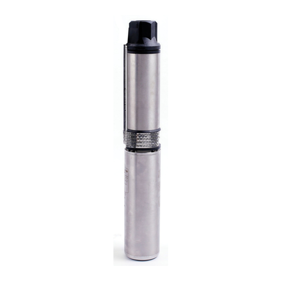
USE AND CARE GUIDE
4 IN. SUBMERSIBLE PUMP
(TWO AND THREE WIRE, ½ - 1HP, 60 HZ)
Questions, problems, missing parts? Before returning to the store,
call Everbilt Customer Service
8 a.m. - 6 p.m., EST, Monday-Friday
1-844-883-1872
HOMEDEPOT.COM
THANK YOU
We appreciate the trust and confidence you have placed in Everbilt through the purchase of this pump. We strive to continually create quality
products designed to enhance your home. Visit us online to see our full line of products available for your home improvement needs. Thank you for
choosing Everbilt!
Advertisement
Chapters
Table of Contents

Related Manuals for Everbilt EFSUB5-122HD


Summary of Contents for Everbilt EFSUB5-122HD
- Page 1 THANK YOU We appreciate the trust and confidence you have placed in Everbilt through the purchase of this pump. We strive to continually create quality products designed to enhance your home. Visit us online to see our full line of products available for your home improvement needs. Thank you for...
-
Page 2: Table Of Contents
Table of Contents Table of Contents ............2 Power Supply Wire INstallation ..........9 Safety Information ............2 Pump Installation ..............10 Warranty ................. 3 Initial Start-Up/New Wells ............10 Pre-Installation .............. 3 Connecting to the Tank/Water System ........11 ... -
Page 3: Safety Information
(i.e. one warranty replacement allowed per purchase). Purchaser pays all removal, installation, labor, shipping, and incidental charges. For parts or troubleshooting assistance, DO NOT return the product to your retail store - contact Everbilt Customer Service at 1-844-883- 1872. - Page 4 Pre-Installation (continued) 4 IN. PUMP DESIGN AND OPTIMUM PERFORMANCE The 4 in. submersible well pumps sold in retail outlets are designed to pump 10 gallons per minute (10 GPM), which is the average size home’s use of water per minute. Larger homes will require larger pumps. 4 in. pumps are built with multiple pumping stages, i.e., 6-10 stages, each lifting water to the next stage and to your application.
-
Page 5: Wiring Connections
Pre-Installation (continued) PLANNING INSTALLATION Inspect the pump and motor for delivery damage. Report any damage immediately to the shipping carrier or to your dealer. The well driller should thoroughly develop the well (that is, pump out all fine sand and foreign matter) before the pump is installed. See the Initial Start-Up section of this document. - Page 6 Wiring Connections (continued) INSTALLATION WIRING - SINGLE PHASE, 3 WIRE WARNING: For motors of 1-1⁄2 HP and above, use a magnetic starter to avoid damage to the pressure switch. Consult factory for wiring information. WARNING: Risk of electric shock. Can shock, burn, or kill. Ensure the ground control box, all metal plumbing, and motor frame with copper wire are in compliance with local codes.
- Page 7 Wiring Connections (continued) Match the motor to the control box as shown below: Voltage Motor No. Control Box No. FM4300531A-01 FM005CB-IR2-01 FM4300731A-01 FM007CB-IR2-01 FM4301031A-01 FM010CB-IR2-01 3-wire quick disconnect box. Follow color coding when Single phase, 2-wire connections. 2-wire pumps have two connecting control box (Yellow to Y, Red to R, Black to B) power supply wire (Black) and one ground wire (Green).
-
Page 8: Installation
Installation WIRE SPLICING Splice wire to motor leads. Use only copper wire for connections to pump motor and control box. TAPED SPLICE (Wire sizes No. 8 (8.4mm ) and larger): Cut off the motor leads. Stagger the lead and wire length so that second lead is 2 in. (50 mm) longer than first lead and third lead is 2 in. -
Page 9: Power Supply Wire Installation
Installation (continued) Center the tubing over the butt connector and apply heat evenly with a torch (a match or lighter will not supply Connector enough heat). Heat Shrink Tubing NOTICE: Keep the torch moving. Too much concentrated heat may damage the tubing. MECHANICAL SPLICE KIT WITH PLASTIC INSULATORS (for 14, 12 and 10 Gauge AWG Wire, or 2, 3 and 5.5 mm wire) Cut off motor leads. -
Page 10: Pump Installation
Installation (continued) PUMP INSTALLATION If a standard air over water pressure tank is used, install two bleeder orifices about 2 ft. (6 M) apart. Orifices will automatically charge the tank with air. NOTICE: If a pre-charged tank is used, DO NOT install bleeder orifices. If the pump and pre-charged tank are replacing a standard tank system, remove bleeder orifices before installing a pump in a well. -
Page 11: Connecting To The Tank/Water System
Installation (continued) Temporary wiring Control center to control center or electrical disconnect box electrical disconnect box Temporary piping Gate valve Pump installation for Pump in well developing a well CONNECTING TO THE TANK/WATER SYSTEM WARNING: Risk of hazardous pressure. Submersible pumps can develop very high pressure in some situations. To prevent tank blowup, install a pressure relief valve able to pass full pump flow at 75 PSI (517kPa) when using an air over water pressure tank. - Page 12 Installation (continued) Control box Electrical (3 wire models only) Disconnect Box Pre-Charged Tank Ground Level Insulated/ Conduit or Sleeve Heated Box Cut-In PSI Cut-Off PSI Pre-charge Well Seal To House Pressure (purchase separately) Service 20 (138 kPa) 40 (276 kPa) 18 PSI Plastic Pipe (124 kPa)
-
Page 13: Troubleshooting
Troubleshooting Symptom Probable Cause Corrective Action The motor will not start but There is no voltage at the fuse box. Replace blown fuses. fuses do not blow. There is no voltage at the pressure switch Replace the faulty pressure switch. There is no voltage at the control box Rewire the supply to the control box. - Page 14 Troubleshooting (continued) The pump starts too There are leaks in the system. Check all tank connections with soapsuds for air leaks. frequently. Check plumbing for leaks. The system must be air and water tight. The pressure switch is defective. Check for a defective switch or switch out of adjustment. Re- adjust or replace the pressure switch.
- Page 15 This page intentionally left blank HOMEDEPOT.COM Please contact 1-844-883-1872 for further assistance.
- Page 16 Questions, problems, missing parts? Before returning to the store, call Everbilt Customer Service 8 a.m. - 6 p.m., EST, Monday-Friday 1-844-883-1872 HOMEDEPOT.COM Retain this manual for future use.
- Page 17 GRACIAS Apreciamos la confianza que ha depositado en Everbilt por la compra de esta bomba. Nos esforzamos por crear continuamente productos de calidad diseñados para mejorar su hogar. Visítenos en internet para ver nuestra línea completa de productos disponibles para sus necesidades de mejorar...
- Page 18 Tabla de contenido Tabla de contenido ............2 Instalación del cable de la fuente de alimentación....9 Información de seguridad ..........2 Instalación de la bomba ............10 Garantía ................3 Arranque inicial/pozos nuevos ..........10 Pre-instalación .............. 3 Conexión al tanque/sistema de agua ........11 Conexiones del cableado ..........
-
Page 19: Información De Seguridad
Para piezas o asistencia de resolución de fallas, NO devuelva el producto a su tienda minorista, póngase en contacto con Servicio al cliente de Everbilt llamando al1-844-883-1872. Los reclamos hechos bajo esta garantía se harán devolviendo el producto (excepto bombas de aguas residuales, ver abajo) a la tienda minorista donde se compró... - Page 20 Pre-instalación (continuación) DISEÑO Y RENDIMIENTO ÓPTIMO DE LA BOMBA DE 4 PULG. Las bombas sumergibles de pozo de 4 plg. que se venden en tiendas minoristas están diseñadas para bombear 10 galones por minuto (10 GPM), que el uso de agua por minuto.de una casa de tamaño promedio. Las casas más grandes requerirán bombas más grandes. Las bombas de 4 plg.
-
Page 21: Conexiones Del Cableado
Pre-instalación (continuación) PLANIFICACIÓN DE LA INSTALACIÓN Inspeccione la bomba y el motor en busca de daños de la descarga. Reporte de inmediato cualquier daño al transportista o a su concesionario. El perforador del pozo debe desarrollar por completo el pozo (o sea, bombear toda la arena fina y el material extraño) antes de instalar la bomba. Consulte la sección Arranque inicial de este documento. - Page 22 Conexiones del cableado (continuación) CABLEADO DE LA INSTALACIÓN - MONOFÁSICO, 3 CABLES ADVERTENCIA: Para motores de 1-1⁄2 HP y mayores, use un arrancador magnético para evitar dañar el interruptor de presión. Consulte con la fábrica para obtener información del cableado. ADVERTENCIA: Riesgo de choque eléctrico.
- Page 23 Conexiones del cableado (continuación) Combine el motor con la caja de control como se muestra a continuación: Voltaje No. de motor No. de caja de control FM4300531A-01 FM005CB-IR2-01 FM4300731A-01 FM007CB-IR2-01 FM4301031A-01 FM010CB-IR2-01 Caja de desconexión rápida de 3 cables Siga la codificación Monofásico, conexiones de 2 cables.
-
Page 24: Instalación
Instalación EMPALME DEL CABLE Empalme el cable a los cables conductores del motor. Use solamente cable de cobre para las conexiones al motor de la bomba y la caja de control. EMPALME CON CINTA (calibres de cable No. 8 (8.4 mm ) y mayores): Corte los cables del motor. -
Page 25: Instalación Del Cable De La Fuente De Alimentación
Instalación (continuación) Centre la tubería sobre el conector de tope y aplique calor uniformemente con una antorcha (un fósforo o encendedor Conector no suministrarán suficiente calor). Tubería del encogimiento del calor AVISO: Mantenga la antorcha en movimiento. Demasiado calor concentrado puede dañar la tubería. JUEGO DE EMPALME MECÁNICO CON AISLANTES PLÁSTICOS (para cables AWG calibre 14, 12 10, o cables de 2, 3 y 5.5 mm Corte los conductores del motor. -
Page 26: Instalación De La Bomba
Instalación (continuación) INSTALACIÓN DE LA BOMBA Si se va a usar un tanque de presión de agua con aire sobre, instale dos orificios de drenado con una separación de 2 pies (6 m) entre sí. Los orificios cargarán automáticamente el tanque con aire. AVISO: Si se usa un tanque precargado, NO instale orificios de drenado. -
Page 27: Conexión Al Tanque/Sistema De Agua
Instalación (continuación) El alambrado provisional para Centro de control centro de control o caja de desconexión eléctrica de la caja de desconexión eléctrica Tuberías temporal Válvula de compuerta Instalación de la bomba para Bomba en el pozo el desarrollo de un pozo CONEXIÓN AL TANQUE/SISTEMA DE AGUA ADVERTENCIA: Riesgo de presión peligrosa. - Page 28 Instalación (continuación) Caja de control Caja de desconexión (Sólo 3 modelos de alambre) eléctrica Pre-cargado el tanque El nivel del suelo Aislado / Conducto o manga caja climatizada Así sello PSI de PSI de corte Presión de Para albergar (se vende por separado) conexión precarga el servicio...
-
Page 29: Resolución De Fallas
Resolución de fallas Síntoma Causa probable Acción correctiva El motor no arranca pero No hay voltaje en la caja de fusibles. Cambie los fusibles explotados. los fusibles no explotan. No hay voltaje en el interruptor de presión. Cambie el interruptor de presión defectuoso. No hay voltaje en la caja de control. - Page 30 Resolución de fallas (Continuación) La bomba arranca con Hay fugas debajo en el sistema. Revise todas las conexiones del tanque con jabonaduras en demasiada frecuencia. busca de fugas de aire. Revise la tubería en busca de fugas. El sistema debe ser a prueba de aire y agua. El interruptor de presión está...
- Page 31 esta página está en blanco HOMEDEPOT.COM Póngase en contacto con el 1-844-883-1872 para asistencia adicional.
- Page 32 ¿Tiene preguntas, problemas o faltan piezas? Antes de regresar a la tienda, ¿Tiene preguntas, problemas o faltan piezas? Antes de regresar a la tienda, llame a Servicio al Cliente de Everbilt llame a Servicio al Cliente de Everbilt de lunes a viernes de 8 a.m. a 6 p.m., hora local del Este de lunes a viernes de 8 a.m.
Need help?
Do you have a question about the EFSUB5-122HD and is the answer not in the manual?
Questions and answers