Panasonic GP-X Series User Manual
Digital displacement sensor
Hide thumbs
Also See for GP-X Series:
- User manual (156 pages) ,
- Specifications (12 pages) ,
- Instruction manual (2 pages)

Related Manuals for Panasonic GP-X Series


Summary of Contents for Panasonic GP-X Series
- Page 1 USER’S MANUAL High-Speed High-Accuracy Eddy Current Digital Displacement Sensor Series ME-GPX(04) No.0031-80V...
- Page 2 Thank you for purchasing Panasonic Industrial Devices SUNX's “GP-X series High-Speed High-Accuracy Eddy Current Digital Displacement Sensor”. Read through this user’s manual for the correct and best operation methods to achieve the optimum performance of our product. Precautions Note that sketches shown in this operation manual may be different from the appearance of the actual product in some respects.
- Page 3 Introduction Precautions and description of notation Chapter 1 Before Starting Operation Chapter 2 Basic Knowledge About Functions Chapter 3 Basic Function Setting Chapter 4 Detail Setting (SET-1) Chapter 5 Special Setting (SET. OP) Chapter 6 RS-232C Communication Function Chapter 7 What to Do Upon an Error Chapter 8 Specifications and Dimensions...
-
Page 4: Table Of Contents
Handling Precautions ................2 Checking the Packaged Components ..........4 Notation ....................4 Chapter 1 Before Starting Operation ............5 1.1 Features of GP-X Series ............... 6 1.2 Basic Configuration ............... 7 1.2.1 Sensor Head ..................7 1.2.2 Controller..................7 1.2.3 Controller Communication Unit and Link Cable... - Page 5 2.2.2 How to Enter a Value ..............31 2.3 Measurement Function ............... 32 2.3.1 Holding Measurement Function ............. 32 2.3.2 Trigger Input ................... 38 2.4 List of Factory Shipment Settings ..........43 Chapter 3 Basic Function Setting ............45 3.1 Memory Selection ............... 46 3.1.1 Memory Number Selection.............
- Page 6 4.6.4 Display Refreshment Period Menu and Display Places Setting ..............89 4.7 Interference Prevention Setting ........... 90 4.8 Memory Switching Method Setting ..........93 4.9 Initialization to Factory Shipment Setting ........94 4.10 Panel Key Lock ................. 95 Chapter 5 Special Setting (SET. OP) ............97 5.1 RS-232C Communication Setting ..........
-
Page 7: Introduction
Introduction Handling Precautions ............2 Checking the Packaged Components .........4 Notation ................4... -
Page 8: Handling Precautions
WARNING Connection ・The GP-X series is configured to satisfy the specification with the combination of the sensor head and the controller. Use the sensor head and controller in combination without fail; with other combinations, not only may the specifications may not be satisfied but also failure may result. - Page 9 <Until June 30 ,2013> Panasonic Electric Works Europe AG Rudolf-Diesel-Ring 2, D-83607 Holzkirchen, Germany <From July 1 ,2013> Panasonic Marketing Europe GmbH Panasonic Testing Center Winsbergring 15, 22525 Hamburg,Germany Conditions Operating Conditions for Compliance with CE ・This is a CE conformity product complying with EMC Directive. The...
-
Page 10: Checking The Packaged Components
Hexagonal nut (For GP-X10M, GP-X12ML and GP-X22KL only) : 2 Toothed washer (For GP-X10M, GP-X12ML and GP-X22KL only) : 1 Instruction manual GP-X GP-X Series CD-ROM Notation Meaning of Symbols Indicates handy points useful for operation. POINT Notice Indicates that care should be taken in regards to operation. -
Page 11: Chapter 1 Before Starting Operation
Chapter 1 Before Starting Operation An outline of the GP-X and mounting, connection and wiring are described. 1.1 Features of GP-X Series ..........6 1.2 Basic Configuration ............7 1.2.1 Sensor Head ............7 1.2.2 Controller .............7 1.2.3 Controller Communication Unit and Link Cable (Optional) .........7 1.2.4 BCD Output Unit (Optional) .........7... -
Page 12: Features Of Gp-X Series
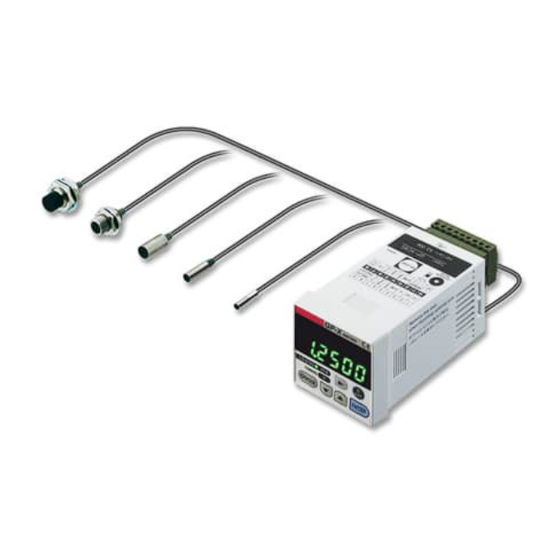
1.1 Features of GP-X Series The GP-X series is a high-speed high-accuracy eddy current digital displacement sensor for measuring the distance to an object. ・Capable of detection of stainless steel (SUS) and iron ・40kHz high-speed sampling ・High resolution and linearity ・Availability of fine 3.8 sensor head... -
Page 13: Basic Configuration
1.2 Basic Configuration 1.2.1 Sensor Head An eddy current flows in the object (metal) to attenuate the amplitude of the coil, as an object (metal) is placed nearer in the high frequency magnetic field generating from the built-in coil. The amount of attenuation is detected and transmitted to the controller. Metal 1.2.2 Controller A sensor head is connected and the displacement between the object (metal) and sensor head is measured and displayed. -
Page 14: Functional Description
1.3 Functional Description 1.3.1 Controller Front panel GP-X series TIMING MODE ENTER Description Function The measurement, calculated value, setting data and so on are displayed. The measurement is displayed in green on Digital display the lower line with the GO judgment, while it is displayed in (green, orange) orange on the upper line with the HI or LO judgment. - Page 15 Rear panel Description Function Upper terminal Connect each terminal to input or output. block Provided with reverse insertion prevention Lower terminal function block Sensor head connection Connect the sensor head. connector Sensor cable Select the cable length of the sensor head cable. length selection Upper side: Standard (3m) extension (7m)
- Page 16 Side view Description Function Connector for Peel the seal off and directly connect the optional unit connection BCD output unit or controller communication unit.
-
Page 17: Bcd Output Unit (Optional)
1.3.2 BCD Output Unit (Optional) Description Function Cable with connector on one end for Connect the BCD output unit. BCD output unit (Optional) Connector for Connect the cable with connector on one end for BCD output BCD output unit Connector for Connect with the side panel of the controller. -
Page 18: Controller Communication Unit (Optional)
1.3.3 Controller Communication Unit (Optional) Description Function Link cable Connects between controller communication (Optional) units. Transmission connector Connect a link cable to communicate with another controller. Reception connector Terminator If only one link cable is connected, turn this switch switch on. (Lower side: ON) Connector for Connect with a controller. -
Page 19: External I/O
1.4 External I/O 1 2 3 4 5 6 7 8 9 10 11 12 13 14 15 16 17 18 Terminal Indication Name Description A signal is output if the measurement LO output is smaller than the lower limit value. A signal is output if the measurement is GO output between the upper and lower limit values. -
Page 20: I/O Circuit Diagrams
1.5 I/O Circuit Diagrams 1.5.1 NPN Output Type (GP-XC S, GP-XC SE, GP-XC M , GP-XC KL) Terminal No. Comparison Load output LO Load 100mA Comparison output GO max. Load Comparison output HI 100mA max. Load 24V DC Load 100mA max. Alarm output 100mA max. -
Page 21: Pnp Output Type
1.5.2 PNP Output Type (GP-XC S-P, GP-XC SE-P, GP-XC M -P, GP-XC KL-P) Terminal No. Output common 100mA max. Comparison output LO 100mA max. 24V DC Comparison output GO 100mA max. Load Comparison output HI 100mA max. Load Alarm output Load 100mA max. -
Page 22: Mounting Method
1.6 Mounting Method The procedure for mounting the GP-X series to a panel is described. 1.6.1 Mounting the Controller 2. Insert the controller into the 1. Cut a mounting hole in the pan- mounting hole from the rear. (unit: mm) +0.6... -
Page 23: Mounting The Sensor Head
1.6.2 Mounting the Sensor Head Tighten the sensor head to the torque specified below. Mounting with set screw Use an M3, or less, cup-point set screw. <Column type> Model A(mm) Tightening torque Set screw (M3 or smaller) (Cup point) GP-X3S 4 to 16 0.1N・m or less GP-X5S 0.44N・m or less 5 to 16 GP-X8S 0.58N・m or less... -
Page 24: Processing And Tightening The Lead Wire
1.6.3 Processing and Tightening the Lead Wire Follow the procedure below to process and tighten lead wires. Lead wire processing size Lead wire Tighten Loosen Dimension A Tightening torque : 0.2N m or less • Recommended tool : Small regular screwdriver (width of 2.5mm or less, thickness 0.5mm or less) -
Page 25: Connection
1.7 Connection 1.7.1 Connecting the Sensor Head and Controller While holding the ring around the connector of the sensor head, insert the connector into the sensor head connector of the controller until it snaps. Controller Sensor head cable length selection switch Sensor head Upper side: Standard (3m) + connection... -
Page 26: Mounting The Option Unit
1.7.2 Mounting the Option Unit Perform mounting after turning the power off. If mounting is performed with the power turned on, failure may result. As well, keep away from mounting brack- ets when the power is on. Mounting of controller communication unit and BCD output unit 1. - Page 27 5. Press portions A of the mounting bracket to snap portions B to fix the fit- ting, as shown in the figure below. 6. Connect the controller communication units as shown in the figure below. Controller communication unit (GP-XCOM) Link cable for controller communication unit (SL-F150/F250/F1000) Terminator switch ON Terminator switch OFF Terminator switch ON 7. Turn the terminator switch ON at the two units located at both ends of the network.
-
Page 28: Flow Of Configuration Until Operation Is Started
1.8 Flow of Configuration Until Operation Is Started 1.8.1 Basic Usage Turn the power on. Refer to section "4.1 Selection of the Object to Select the material of the object to be detected. Be Detected" on page 70. Refer to section "4.2 Three-Point Calibration Adjust linearity. -
Page 29: Chapter 2 Basic Knowledge About Functions
Chapter 2 Basic Knowledge About Functions 2.1 Displaying Operation ............24 2.1.1 Operation Panel ...........24 2.1.2 List of Characters Displayed at Controller ....25 2.2 Operation System ............26 2.2.1 Overview of Operation System ......26 2.2.2 How to Enter a Value ...........31 2.3 Measurement Function ..........32 2.3.1 Holding Measurement Function ......32 2.3.2 Trigger Input ............38 2.4 List of Factory Shipment Settings .........43... -
Page 30: Displaying Operation
2.1 Displaying Operation 2.1.1 Operation Panel GP-X series TIMING MODE ENTER Description Function The measurement, calculated value, setting data and so on are displayed. The measurement is displayed in green on Digital display the lower line with the GO judgment, while it is displayed in (green, orange) orange on the upper line with the HI or LO judgment. -
Page 31: List Of Characters Displayed At Controller
2.1.2 List of Characters Displayed at Controller... -
Page 32: Operation System
2.2 Operation System 2.2.1 Overview of Operation System Display/confirmation Setting mode Detection state Memory number selection (Refer to page 46.) Upper limit value Upper limit value (Refer to page 48.) Lower limit value Lower limit value (Refer to page 48.) Averaging Averaging frequency (Refer to page 51.) - Page 33 Detection Mode When the orange MODE indicator next to the key is not lit, the sensor is in the detection state. Judgment is output in the detection state accord- ing to the upper and lower limit settings. With the GO judgment, a value is displayed in green on the lower line.
- Page 34 Zero Setting Press and hold the key on the panel for longer than two seconds to change the current position of the detected object to the zero (reference) po- sition while the displayed value and analog voltage output are zeroed. Use this key to adjust the reference position according to a slight difference in the detected object or according to the workpiece positions varying as time passes.
- Page 35 Turn on the panel key lock function to protect the memory if zero setting from the external terminal is used frequently. Notice (The maximum memory writing frequency is 100,000 cycles.) *To perform zero setting, set the detection distance within 1/2 F.S. If the de- tection distance between the measurement result and zero setting exceeds 1.5 times F.S., calculation may not be performed correctly.
- Page 36 Setting Mode When the key is pressed, the MODE indicator (orange) lights up to start the setting mode. At this time, the controller continues sampling, measurement and judgment. Press the key to change the setting of major items. Reference Display Name Reference item page...
-
Page 37: How To Enter A Value
2.2.2 How to Enter a Value The value entry method for the upper limit is described as an example. Setting Example Change upper limit setting 2.0000mm to 4.5000mm. 1. In the detection state, press the key. The MODE indicator (orange) next to the key lights up to indicate the setting mode, and the current memory number is displayed. -
Page 38: Measurement Function
2.3 Measurement Function 2.3.1 Holding Measurement Function The holding measurement function includes the following variations. Display Name Description of action The measurement result is displayed and Normal output. The maximum value at the designated Peak hold interval is measured. The minimum value at the designated Bottom hold interval is measured. - Page 39 Peak Hold: The maximum detection value in the interval designated with trigger inputs is held. For the trigger input, the external trigger of timing input, internal trigger with designation of the trigger level, or cyclic trigger with designation of a period can be used.
- Page 40 Bottom Hold: The minimum detection value in the interval designated with trigger inputs is held. For the trigger input, the external trigger of timing input, internal trigger with designation of the trigger level, or cyclic trigger with designation of a period can be used.
- Page 41 Peak-to-Peak Hold: The difference between the maximum and minimum detection values in the interval designated with trigger inputs is held. For the trigger input, the external trigger of timing input, internal trigger with designation of the trigger level, or cyclic trigger with designation of a period can be used.
- Page 42 Sample Hold: The value detected at the time trigger input is held. For the trigger input, the external trigger of timing input, internal trigger with designation of the trigger level, or cyclic trigger with designation of a period can be used. Holding measurement begins with the power on or immediately after reset input is turned on.
- Page 43 Average Hold: The simple mean of detected values in the period designated with trigger in- puts is held. For the trigger input, the external trigger of timing input, internal trigger with designation of the trigger level, or cyclic trigger with designation of a period can be used.
-
Page 44: Trigger Input
2.3.2 Trigger Input When various holding measurement functions are used, the external trigger given at the external terminal (timing input) and internal trigger can be used to take measurements at various timings. In addition, trigger delay and sampling time can be entered and the sampling period can be adjusted. - Page 45 External Trigger Mode Example of peak hold Measured value Output of result of Measurement sampling period 2 Displayed value Output value Output of result of sampling period 4 Displayed value Output of result of sampling period 1 Timing input Reset input Sampling Sampling Internal sampling...
- Page 46 Internal Trigger Mode In the internal trigger mode, sampling begins after the trigger delay (td) since the trigger is generated, and the sampling period is finished after the sam- pling time (ts). The displayed output, analog voltage output and upper/lower limit judgment are updated at the end of the sampling period.
- Page 47 If sampling time (ts) = 0 Measured value Measurement Displayed value Output value End of sampling End of sampling Trigger point Trigger point Trigger hysteresis Trigger level Measured value Displayed value Output of result of sampling period 2 Output of result of sampling period 1 Trigger delay Internal...
- Page 48 Cyclic Trigger Mode In the cyclic trigger mode, the trigger is generated periodically and held in the trigger interval. The trigger is generated for each period. The interval from the trigger point to the next trigger point is the sampling pe- riod.
-
Page 49: List Of Factory Shipment Settings
2.4 List of Factory Shipment Settings Indication on Indication on Factory shipment setting Item upper line lower line Memory number Memory 0 Varies according to each model No. GP-XC3S(-P) 0.6400mm GP-XC5S(-P) 0.8000mm Upper limit value GP-XC8S(-P), GP-XC10M(-P) 1.6000mm GP-XC12ML(-P) 4.0000mm GP-XC22KL(-P) 8.000mm Varies according to each model No. - Page 50 Indication on Indication on Factory shipment setting Item upper line lower line Default Analog voltage output scale At max. detection distance 5.0V Display setting Item displayed in upper line Default Item displayed in lower line Default Displaying unit Power saving mode Invalid Display refresh period 20 cycles/sec.
-
Page 51: Chapter 3 Basic Function Setting
Chapter 3 Basic Function Setting 3.1 Memory Selection ............46 3.1.1 Memory Number Selection ........46 3.1.2 Memory Copy Function ........47 3.2 Upper and Lower Limit Value Settings ......48 3.2.1 Setting the Upper and Lower Limit Value Entry Method ............48 3.2.2 Value Entry Setting (Direct value entry) ....49 3.2.3 Using the Actual Detection Value to Set (Teaching) ............50 3.3 Averaging Frequency Setting ........51... -
Page 52: Memory Selection
3.1 Memory Selection Various conditions are saved in the controller in up to four memories (No. 0 to 3). The memory number can be switched using a panel key or external terminal. Reference For external input/output, refer to section "1.4 External I/O" on page 13. Reference For the selection of the switching method, refer to section "4.8 Memory Switching Method Setting"... -
Page 53: Memory Copy Function
3.1.2 Memory Copy Function With the memory copy function, the settings of the currently selected memory number are duplicated to another memory. Use this function to leave most of the settings unchanged with partial changes and use the memory switching function. -
Page 54: Upper And Lower Limit Value Settings
3.2 Upper and Lower Limit Value Settings Set the upper and lower limit values for the judgment of the measured value. Judgment is made as to the comparison between the value after display scaling and the upper and lower limit settings. Before entering the upper limit value, determine the display scale. -
Page 55: Value Entry Setting (Direct Value Entry)
3.2.2 Value Entry Setting (Direct value entry) Setting example Change the upper limit value from "1.5000" to "1.4000". <Detection state> Press to select "H-thr". Upper limit value setting mode Press to move to another digit. Press to change the number. Press to set. -
Page 56: Using The Actual Detection Value To Set (Teaching)
3.2.3 Using the Actual Detection Value to Set (Teaching) Setting example Change the upper limit value from "1.5000" to "1.7000". <Detected state> Press to select "H-thr". Press and hold for more than two seconds to teach. Upper limit value setting mode The blinking value indicates that the distance between sensor... -
Page 57: Averaging Frequency Setting
3.3 Averaging Frequency Setting Change the averaging frequency to obtain the best relationship between the response time and variation in detection. If high-speed judgment is necessary, set a smaller averaging frequency. For momentary changes or fine judgment, set a larger averaging frequency to suppress any variation in detection. -
Page 58: Setting According To Application (Application Mode)
3.4 Setting According to Application (Application mode) 3.4.1 Selecting the Application Mode In the application mode, setting items change according to each application. Because only the items necessary for the application mode are displayed, data entry is easy. There are the following four variations in the application mode. - Page 59 ・Height detection mode: " " (height) The reverse value change direction is selected. The sample hold and external trigger modes are automatically selected. Displayed value Time Select "Default" for the application mode to restore the factory shipment settings of the application mode. Note that the negative span (inclination) setting of scaling changes to the positive span (inclination) after restoration of default settings.
-
Page 60: Manual Mode
3.4.2 Manual Mode: " " (manual) There are the following variations in the detection function that are available in the manual mode. Indication Name Description of action The measurement result is displayed and Normal output whenever necessary. The maximum value in the designated Peak hold interval is measured. -
Page 61: Press Bdc Detection Mode
Be Detected" on page 70. If the object is made of iron, select "FE". The factory shipment setting of GP-X series is stainless steel (SUS304). 2. At the reference bottom dead center position, adjust so that the distance between the sensor head and the object to be detected becomes the center (halfway position) of the detection range. - Page 62 4) Select the press BDC detection mode. After the bottom dead center (BCD) detection mode is selected, a menu for entering the following settings opens. ・Internal trigger level ・Trigger hysteresis ・Comparison with previous mean valid/invalid <Detection state> Press to select "APPLI". <Application mode>...
-
Page 63: Rotation/Eccentricity Detection Mode
Reference Refer to section "4.1 Selection of Object to Be Detected" on page 70 for selection of the material. If the object to be detected is iron, select "FE". The factory shipment setting of GP-X series is stainless steel (SUS304). - Page 64 2. Adjust so that the distance between the sensor head and the object to be detected is at the center (half the distance) of the detection range. Perform adjustment while observing the distance displayed on the controller. To perform zero setting, set the detection distance within 1/2 F.S. If the de- tection distance between the measurement result and zero setting exceeds Notice 1.5 times F.S., the calculation may not be made correctly.
- Page 65 6) Rotate the detected body to start detection. The peak-to-peak distance is displayed upon a trigger based on the minimum point of the rotating body and judgment is output concerning the displayed value. "-----" is displayed until the first measurement result is obtained. If the deviation is smaller than the hysteresis, no trigger is generated.
-
Page 66: Height Detection Mode
3.4.5 Height Detection Mode: " " (height) This mode is convenient to detect the height of a metallic part such as a screw or rivet etc. After the "height detection mode" is selected, the following measuring conditions are configured. ・Holding measurement mode is fixed at sample hold. ・The trigger condition is fixed at external trigger. - Page 67 4) Select the height detection mode. <Detection state> Press to select "APPLI". <Application mode> <BDC detection mode> <Rotation/eccentricity mode> <Height detection mode> Negative slope End of entry Press the key to return. 5) Set the tolerance judgment value. Enter the upper and lower limit values for GO judgment in respect to the reference position (zero point).
- Page 68 Height detection mode Detected value Upper limit value Lower limit value Timing input HI output GO output LO output Start of measuring mode...
-
Page 69: Trigger Input Setting
3.5 Trigger Input Setting There are the following trigger input types for determining the sampling period. Select the desired trigger mode. ■ External Trigger: " " (Ext) Supply a signal from an external device using the timing input and reset input terminal, to determine the sampling period. -
Page 70: External Trigger Setting
3.5.1 External Trigger Setting The external trigger is selected. However, if the external trigger is selected, the trigger direction, trigger level, trigger hysteresis, trigger delay and sampling entered for the internal trigger are ignored. 3.5.2 Internal Trigger Setting When the internal trigger is entered, the operation menu proceeds accord- ing to the following procedure. -
Page 71: Cyclic Trigger Setting
・Enter the settings so that the trigger level and the sum of the trigger level and trigger hysteresis become within 110% and 120% of the maximum detection distance, respectively. Example: 2mm type sensor head Trigger level: 2.2mm Trigger level + trigger hysteresis: 0 to 2.4mm POINT ・... -
Page 72: Comparison With Previous Mean
3.6 Comparison with Previous Mean With comparison with the previous mean, a moving mean of held values up to the previous cycle is made the reference value (zero) to offset slow changes caused by aging or temperature. This function can only be made effective for the press BDC detection mode. Zero setting is necessary at the reference position. - Page 73 Setting example <Detection state> Press to select "CoMP". Comparison with previous mean Press to select "on".
- Page 74 MEMO...
-
Page 75: Chapter 4 Detail Setting (Set-1)
Chapter 4 Detail Setting (SET-1) 4.1 Selection of Object to Be Detected .......70 4.2 Three-Point Calibration (Linearity adjustment) .....71 4.3 Judgment Output Setting ..........73 4.3.1 Judgment Hysteresis ..........73 4.3.2 Output Style Selection ..........73 4.3.3 Output Delay ............74 4.4 Display Scale ..............76 4.4.1 One-Point Scaling ..........76 4.4.2 Two-Point Scaling ..........78 4.4.3 INV Function ............80... -
Page 76: Selection Of Object To Be Detected
4.1 Selection of Object to Be Detected The GP-X series is configured before shipment from the factory so that lin- ear accuracy is achieved for stainless steel (SUS304). If the material of the object to be detected is other than stainless steel, change the setting. -
Page 77: Three-Point Calibration (Linearity Adjustment)
4.2 Three-Point Calibration (Linearity adjustment) For the GP-X series, linearity adjustment in respect to the distance is made before shipment from the factory with a set of a sensor head and controller. If adjustment is made for the material to be detected and operating environ- ment, linearity with increased accuracy is obtained. - Page 78 Calibration can be made in each memory for each object material. A total 12 sets of calibration data can be stored with a product with four memories and three materials. Select "mEm- " in the calibration menu. " " indicates the current memory number. To perform common calibration for four memories, select "mEm-A", and per- form calibration for the current material.
-
Page 79: Judgment Output Setting
4.3 Judgment Output Setting 4.3.1 Judgment Hysteresis Determine the hysteresis of the upper and lower limit values. Enter the value corresponding to the display. The hysteresis is defined inside the upper or lower limit value (in the GO area). Enter the setting corresponding to the displayed value. Enter the value so that the following equation stands true: Upper limit value (H-thr) - hysteresis width (o-hys) >... -
Page 80: Output Delay
4.3.3 Output Delay Select the off-delay timer setting from the options shown in the table below. Delay Description of action Indication in lower line No delay No delay 100ms 100ms off-delay 200ms 200ms off-delay 400ms 400ms off-delay 800ms 800ms off-delay 1,000ms 1,000ms off-delay Judgment output is held until the reset... - Page 81 Setting example Set the judgment hysteresis at 0.0100mm, output style at normally closed (N.C.), and output delay at 100ms. <Setting 1 mode> Press to select "HGL-o". Judgment output setting <Judgment hysteresis> Press to move to another digit. Press to change the number. <Output style>...
-
Page 82: Display Scale
4.4 Display Scale Define the display range of the detected value. The distance of the detected object from the sensor head is displayed with the factory shipment setting. With the scaling function, you can arbitrarily change the value displayed ac- cording to the detected value. - Page 83 Setting example <Setting 1 mode> Press to select "d-ScL". <Display scale> Press to select "1-ScL". Press to select "SLOPE". Press to move to another digit. <Value entry mode> <Value entry mode> Press change the number. Press and hold <Teaching mode> Press to move to another digit.
-
Page 84: Two-Point Scaling
4.4.2 Two-Point Scaling The span (inclination) and offset of the displayed value can be defined arbi- trarily. Set P1 (0.5mm) at "0.0000" and P2 (2mm) at "3.0000". Display 3.0000 Display 2.0000 2.0000 0.5mm ・Enter the first and second points. ・Enter the detected value on the upper line and the value to be displayed on the lower line. - Page 85 Setting example <Setting 1 mode> Select to select "d-ScL". <Display scale> Press to select "2-ScL". Press to proceed to the second point. Press to move to Press to move to another digit. another digit. <Value entry mode> Press <Value entry mode> Press change the number.
-
Page 86: Inv Function
4.4.3 INV Function With both the one-point and two-point scaling, use the INV function to re- verse the inclination. However, the INV function reverses the inclination around the 1/2 F.S. point, different from "SLOPE" of one-point scaling. 2.0000 2.0000 1.0000 Setting example <Setting 1 mode>... -
Page 87: Analog Voltage Output Scale
4.5 Analog Voltage Output Scale Define an analog voltage output range in proportion to the detected value. The full-scale is set in the range from 0 to 5.0V before shipment from the fac- tory. An analog voltage output range, inclination and other features of the detect- ed value can be entered. - Page 88 Setting example <Setting 1 mode> Press to select "o-ScL". Analog voltage output scale Press to select "1-ScL". Press to select "SLOPE". Press to move to another digit. <Value entry mode> <Value entry mode> Press change the number. Press and hold <Teaching mode>...
-
Page 89: Two-Point Scaling
4.5.2 Two-Point Scaling The span (inclination) and offset of analog voltage output can be set arbi- trarily. Set P1 (0.5mm) at "0.0000" and P2 (2mm) at "3.0000". Voltage 5.0000 Voltage 5.0000 3.0000 0.5mm -1.0000 ・Enter the first and second points. ・Enter the detected value on the upper line and the displayed value on the lower line. - Page 90 Setting example <Setting 1 mode> Press to select "o-ScL". Analog voltage output scale Press to select "2-ScL". Press to proceed to the second point. Press to move to Press to move to another digit. another digit. <Value entry mode> Press Press <Value entry mode>...
-
Page 91: Inv Function
4.5.3 INV Function With both one-point and two-point scaling, use the INV function to reverse inclination. However, the output reverses around the 1/2 F.S. point, different from "SLOPE" of one-point scaling. 2.0000 2.0000 1.0000 Setting example <Setting 1 mode> Press to select "o-ScL". -
Page 92: Display Setting
4.6 Display Setting 4.6.1 Selection of Data Displayed in Upper and Lower Lines The items displayed on the panel in the detection state can be designated. In the factory shipment state, the "HI/LO detected value" is displayed on the upper line (orange) and the "GO detected value" on the lower line (green). Upper line (Orange) Lower line (Green) Setting example... -
Page 93: Selecting The Display Unit
4.6.2 Selecting the Display Unit Distance display (mm) or output voltage display (volt) can be selected. With the distance display (mm), a value after display scaling is displayed. With the voltage output (volt), a voltage output is displayed so that the dis- play scale agrees with the analog voltage output value. -
Page 94: Power Saving Mode Setting
4.6.3 Power Saving Mode Setting After settings are entered, you can turn off the digital display to save power. This function is especially useful to reduce power consumption in a system with multiple controllers. Setting method Press to select "Eco". Press to select "on". -
Page 95: Display Refreshment Period Menu And Display Places Setting
4.6.4 Display Refreshment Period Menu and Display Places Setting The display refreshment period and the number of displayed digits can be changed. 1) Display refreshment period The refreshment period of the displayed value can be changed. Select the refreshment frequency per second. The factory shipment setting is "20". -
Page 96: Interference Prevention Setting
4.7 Interference Prevention Setting Connect the interference prevention output (terminal No. 7) at the external terminal and the interference prevention input (terminal No. 16) to switch the detection action alternately to prevent mutual interference from occurring. Because the detection action switching signal is automatically generated, there is no need to supply pulse signals for switching the action. - Page 97 3) Designate controllers 2 and 3 as slaves. Press to select "slave". (Slave) Timing chart of interference prevention action Oscillation stop (measurement value hold) interval Measurement Measurement Controller 1 (Master) Oscillation stop (measurement value hold) interval Measurement Measurement Controller 2 (Slave) Measurement Controller 3...
- Page 98 Setting items related to time: Trigger delay, sampling time, cyclic trigger, output off-delay For example, with a "1.0 sec." setting of the cyclic trigger in a system con- necting three units, the actual period becomes 4.8 sec. To obtain a 1.0 sec. period, enter "0.2083 sec."...
-
Page 99: Memory Switching Method Setting
4.8 Memory Switching Method Setting To switch the memory number for storage of settings described in sec- tion "3.1 Memory Selection", there are two methods: panel key operation method and external input method. Select the appropriate method otherwise memory switching will not occur. The factory shipment setting is panel key operation. -
Page 100: Initialization To Factory Shipment Setting
4.9 Initialization to Factory Shipment Setting Factory shipment settings other than the calibration and sensor head re- placement mode can be restored. Reference For the initial setting items, refer to section "2.4 List of Factory Shipment Settings" on page 43. Setting example <Setting 1 mode>... -
Page 101: Panel Key Lock
4.10 Panel Key Lock Use this function to prohibit key operation on the front panel. Erroneous operations of operation keys can be avoided. If any key is pressed after the panel key is locked, "KEY LOCK" is displayed for about one second. The panel key can only be locked in the detection state. - Page 102 MEMO...
-
Page 103: Chapter 5 Special Setting (Set. Op)
Chapter 5 Special Setting (SET. OP) 5.1 RS-232C Communication Setting .........98 5.1.1 Communication Specification Item .......98 5.1.2 Setting Procedure ..........98 5.1.3 Connector Pin Layout on Controller Side .....99 5.2 Settings Related to BCD Output Unit (Optional) ..100 5.2.1 Overview of Specifications of BCD Output Unit ............100 5.2.2 BCD Output Selection Procedure ......102 5.3 Settings Related to Controller Communication... -
Page 104: Rs-232C Communication Setting
5.1 RS-232C Communication Setting 5.1.1 Communication Specification Item Function Name Options of mode 115.2k 57,600 38,400 Baud rate 19,200 9,600 4,800 2,400 Parity parity EVEN NONE stopb Stop bits *The data length is fixed at 8 bits and flow control is not made. 5.1.2 Setting Procedure Setting example Change the baud rate from 19,200 bps to 9,600 bps. -
Page 105: Connector Pin Layout On Controller Side
ER (DTR) Applicable connector (Reference): TCP6180 (Hoshiden) Wiring example PC-AT compatible GP-X series Pin No. Signal name Pin No. RS-232C cable (3m): Use ANM81103 Note: "RS" and "CS" are not used for GP-X series. Deselect flow control on the PC side. -
Page 106: Settings Related To Bcd Output Unit (Optional)
5.2 Settings Related to BCD Output Unit (Optional) 5.2.1 Overview of Specifications of BCD Output Unit High-speed digital output can be obtained through connection of a BCD output unit (GP-XBCD) (optional) and a cable with connector on one end for BCD output unit (GP-XBCC3) (optional). - Page 107 The BCD output does not support decimal point shift caused by carry-over. Therefore, select "4" in advance for the number of displayed digits if a deci- mal point shift is foreseen. For the setting method of the number of displayed digits, refer to Section "4.6.4 Display Refreshment Period Menu and Dis- play Places Setting"...
-
Page 108: Bcd Output Selection Procedure
I/O Circuit Output circuit diagram (terminal No. 1 to 22) Positive logic. Nch MOS FET open drain Load 50mA max. DC power supply Users' circuit Internal circuit Input circuit diagram (terminal No. 23) Input Input Non-voltage contact or NPN open-collector transistor Users' circuit Internal circuit 5.2.2 BCD Output Selection Procedure... -
Page 109: Settings Related To Controller Communication Unit (Optional)
5.3 Settings Related to Controller Communication Unit (Optional) 5.3.1 Overview of Controller Communication Unit Using the controller communication unit (GP-XCOM) (optional) and link cable for controller communication unit (SL-F150/F250/F1000) (optional), data communication among multiple controllers becomes possible, and calculation between two units, setting data transfer, multiple settings via RS- 232C can be used. -
Page 110: Connection Of Controller Communication Unit And Address Setting
2) The sampling frequency of the calculation Sampling frequency No. of connected units conducted between two units varies accord- 200 s approx. 400 s approx. ing to the total number of units connected in 600 s approx. the network. 800 s approx. 3) As an analog voltage output, the voltage detected at one unit is output, instead of a value calculated for the two units. - Page 111 4. Turn the controller on and assign an address to each controller according to the following procedure. Select one (master) beyond the connected controllers and perform automatic address assignment. The address of the selected controller becomes "0". <Option> Press to select "com". <Manual setting>...
-
Page 112: Calculation Between Controllers
5.3.3 Calculation Between Controllers Among controllers connected with controller communication unit, designate two units to perform calculation and make judgment according to the result of calculation. Suppose that detected values at two units are "A" and "B". The following cal- culations can be made. - Page 113 <How to cancel calculation setting> After performing calculation between two controllers, reset either the master controller or slave controller to cancel calculation. The resetting method varies between the master and slave. How to cancel master controller after calculation <Option> Press to select "com".
-
Page 114: Sensor Head Replacement Setting
5.4 Sensor Head Replacement Setting 5.4.1 Interchangeability of Sensor Head In case the sensor head is broken, the sensor head replacement is possible with same model. (in the case, enter a characteristics code (ID code) into the controller ) Using the ID type linearity correction function having been developed for the current application, high accuracy identical to that of the factory shipment setting can be maintained. - Page 115 2. Enter the 10-digit number of the desired material specified on the tag. *If a different material code is entered, an error is caused. <Detection state> Press to select "set.op". <Option mode> Press to select "head". "deflt" indicates the characteristics <Characteristics code entry mode>...
-
Page 116: Software Version Display Menu
5.5 Software Version Display Menu The version data of the software built into the controller can be checked. <Detection state> Press to select "set.op". <Option mode> Press to select "SoFt.v". <Software version> For the GP-XC3SE(-P) or GP-XC5SE(-P), the bottom indication is ended by " ". -
Page 117: Chapter 6 Rs-232C Communication Function
Chapter 6 RS-232C Communication Function 6.1 How to Use RS-232C Commands ......112 6.2 Command Lists ............114 6.3 Intelligent Monitor Software (GP-XAiM) (Optional) ..132... -
Page 118: How To Use Rs-232C Commands
6.1 How to Use RS-232C Commands To control the GP-X series via the RS-232C, follow the procedure below. 1. Connect a communication cable between the controller and a host (PC etc.). 2. Maintain consistency in the communication specification between the controller and the host (PC etc.). - Page 119 Response Format Response to loading command The transmission and response format for a value is always "%9.4f". With some types of transmission command, it takes a long time before the response is issued. (Max. approx. 5 sec.) Signed value (Upper/lower limit value, scaling) Header Command Controller...
-
Page 120: Command Lists
6.2 Command Lists Basic control command Controller Command Instruction character Setting Item Outline address string (m) example Loading Writing (n) 1) The measured value is loaded from the controller of the designated address. The response to E # R M D n m Displayed Loading value... - Page 121 Basic control command Controller Command Instruction character Setting Item Outline address string (m) example Loading Writing (n) 1) Load the entered application mode data. The response to E # R A P E $ R A P n m <Response value m> m = 0: Manual mode m = 1: BDC mode m = 2: Eccentricity measurement mode...
- Page 122 Basic control command Controller Command Instruction character Setting Item Outline address example string (m) Loading Writing Upper/lower limit value Load the current lower limit value setting. The response to E # R L T n 0 E $ R L T n + &...
- Page 123 Basic control command Controller Command Instruction character Setting Item Outline address string (m) example Loading Writing (n) 1) Load the current memory number setting. The response to E # R M M n 0 E $ R M M n m Memory switch Enter the memory number of the controller of the designated address.
- Page 124 Command for adjustment Controller Command Instruction character Setting address Item Outline string (m) Loading Writing example (n) 1) Perform or cancel zero setting of the controller of the designated address. The response to Zero setting ON Example 7 Zero setting E # W Z S n m Zero setting OFF E $ W Z S n...
- Page 125 Command for adjustment Controller Command Instruction character Setting Item Outline address string (m) example Loading Writing (n) 1) Scaling The analog voltage output scale is set for the controller at the designated address. There are seven types of setting commands. You can use them according to the 0: X1_Y1 (1st purpose.
- Page 126 Command for adjustment Controller Command Instruction character Setting Item Outline address string (m) example Loading Writing Scaling Load the current scaling data of displayed measurement. The detected distance and the corresponding displayed value are sent back. <Loading the setting of each scaling point> % E E # R S D n m m = 0 or 1 The response to the above command is:...
- Page 127 Command for adjustment Controller Command Instruction character Setting Item Outline address string (m) example Loading Writing (n) 1) Scaling <First point teaching in two-point scaling> With the detection target set to the <Data format> scaling distance, set and send the analog X1 and X2 are voltage output values.
- Page 128 Command for adjustment Controller Command Instruction character Setting Item Outline address string (m) example Loading Writing (n) 1) Sensor head replacement Load the sensor head characteristics ID each material preset designated controller. 0 to 2 The response to Interchange- Stainless steel ability data (SUS) E # R G D n m...
- Page 129 Input/output/trigger Controller Command Instruction character Setting Item Outline address string (m) example Loading Writing Load the internal trigger edge direction data. The response to E # R G n 0 (Internal) E $ R E G n m trigger edge Enter the edge direction of the internal trigger.
- Page 130 Input/output/trigger Controller Command Instruction character Setting Item Outline address string (m) example Loading Writing Load the cyclic trigger time width. The response to E # R T n m E $ R & & & & . & & & &...
- Page 131 Input/output/trigger Controller Command Instruction character Setting Item Outline address string (m) example Loading Writing (n) 1) Load the interference prevention function validity setting. The response to E # R K B n 0 E $ R K B n m <Response value m>...
- Page 132 Display setting Controller Command Instruction character Setting Item address Outline string (m) example Loading Writing (n) 1) Enter the unit of displayed value or display period and number of digits. The response to Distance display % E E # W U T n m Analog voltage % E E # W U T n 2 p q Display unit...
- Page 133 System / Option Controller Command Instruction character Setting Item Outline address string (m) example Loading Writing (n) 1) RS-232C setting Load RS-232C communication specification setting. The response to # R S A n 0 $ R S A n The factory shipment settings of the RS-232C communication conditions are: 19200bps, odd parity, 1 stop bit, and 8 bit data length.
- Page 134 9: Data buffering With data buffering, sample data collected in the GP-X series at high speed temporarily accumulates in the controller in reference to trigger conditions and, upon completion of accumulation, the data is loaded via RS-232C communication. About 120,000 points of data can be accumulated.
- Page 135 Examples of Application of RS-232C Commands Example 1: Load the current displayed value from controller address 0. Transmission: %EE#RMD00 Response: %EE$RMD0+000.4500 The current displayed value is "(+) 0.4500". If holding mea- surement is designated, the hold value is sent back. Example 2: Load the judgment data from controller address 0.
- Page 136 After setting the full-scale distance in the detection range, send. Transmission: %EE#WCG03 Response: %EE$WCG0 Save the offset and start enactment. Transmission: %EE#WCG04 Response: %EE$WCG0 Example 7: Perform zero setting for controller address 0. Transmission: %EE#WZS00 Response: %EE$WZS0 To cancel zero setting, Transmission: %EE#WZS01 Response: %EE$WZS0 Example 8: Load the analog voltage output scaling data from controller ad-...
- Page 137 Application Mode Setting To designate the application mode using RS-232C commands, set each mode, followed by the necessary items. 1) Bottom dead center detection mode Select the BDC detection mode. Transmission: %EE#WAP01 Response: %EE$WAP0 Set the trigger level (WTT). Set the level at "0.8000". Transmission: %EE#WTT0+000.8000 Response: %EE$WTT0 Set the trigger hysteresis (WTH).
-
Page 138: Intelligent Monitor Software (Gp-Xaim) (Optional)
6.3 Intelligent Monitor Software (GP-XAiM) (Optional) With the optional intelligent monitor software (GP-XAiM), the measurement data can be easily analyzed or saved at your PC while conditions can be entered, saved or loaded. Use these features together with the data buffering function of the controller to acquire ready-to-analyze data assuredly. -
Page 139: Chapter 7 What To Do Upon An Error
Chapter 7 What to Do Upon an Error 7.1 Error Indication List .............134 7.2 What to Do? ..............136... -
Page 140: Error Indication List
7.1 Error Indication List Error indication Alarm Resetting key Description of error Remedy output Upper line Lower line Turn the power off then EEPROM data Press and hold on again. If the error loading error persists, initialize settings restore factory Or enter an external EEPROM data... - Page 141 Error indication Resetting key Alarm Description of error Remedy Upper line Lower line output Voltage output scale error. This occurs when same distance value Enter the correct scale. voltage value Distance setting range: entered for the first P r e s s 0mm to 110% of F.S.
-
Page 142: What To Do
7.2 What to Do? When the following phenomenon occurs, check. Reference S y m p t o m Confirmation method and remedy page Check that the cables are connected correctly. P.14 All indicators do not light up. Check that the power saving mode starts without a P.88 trigger in the holding measurement mode. -
Page 143: Chapter 8 Specifications And Dimensions
Chapter 8 Specifications and Dimensions 8.1 Ratings and Performance ...........138 8.1.1 Sensor Head ............138 8.1.2 Controller ............139 8.1.3 BCD Output Unit and Controller Communication Unit ...........141 8.2 Dimensions (Unit: mm) ..........142 8.2.1 Sensor Head ............142 8.2.2 Controller ............145 8.2.3 BCD Output Unit (Optional) ........145 8.2.4 Controller Communication Unit (Optional) ..145... -
Page 144: Ratings And Performance
8.1 Ratings and Performance 8.1.1 Sensor Head 3.8mm type 5.4mm type 8mm type M10 type M12 type 22 type Type GP-X3S(E) GP-X5S(E) GP-X8S GP-X10M GP-X12ML GP-X22KL Item Model No.(Note1) Sensing range (Note 2) 0 to 0.8mm 0 to 1mm 0 to 2mm 0 to 5mm 0 to 10mm Standard sensing object... -
Page 145: Controller
8.1.2 Controller Set model name NPN output GP-XC3S GP-XC5S GP-XC8S GP-XC10M GP-XC12ML GP-XC22KL GP-XC3SE GP-XC5SE (Note 1) PNP output GP-XC3S-P GP-XC5S-P GP-XC8S-P GP-XC10M-P GP-XC12ML-P GP-XC22KL-P GP-XC3SE-P GP-XC5SE-P Item Supply voltage 24V DC 10% Ripple P-P 10% or less Current consumption 150mA or less Output voltage: 5 to... - Page 146 When a different power supply is used for 2, or more, controllers, be sure to connect either 0 V lines or +V lines of the controllers each other. Other- Notice wise, the transmission by GP-XCOM and the interference prevention func- tion are not properly operated.
-
Page 147: Bcd Output Unit And Controller Communication Unit
8.1.3 BCD Output Unit and Controller Communication Unit Designation BCD output unit Controller communication unit Item Model No. GP-XBCD GP-XCOM Model of combination set GP-XC , GP-XC Current consumption 20mA or less 5mA or less (mounting to GP-XC N channel MOS FET open drain Output Maximum sink current: 50mA 5-digit BCD... -
Page 148: Dimensions (Unit: Mm)
8.2 Dimensions (Unit: mm) 8.2.1 Sensor Head GP-X3S / 3.8mm type 2.5 high frequency coaxial cable 3m Coaxial connector for connection of controller ( 6.4) (25.7) GP-X5S / 5.4mm type 2.5 high frequency coaxial cable 3m Coaxial connector for connection of controller (6.2) 6.4) (25.7) - Page 149 GP-X8S / 8mm type 2.5 high frequency coaxial cable 3m Coaxial connector for connection of controller (6.2) 6.4) (25.7) GP-X10M / M10 type 2.5 high frequency coaxial cable 3m (6.2) Coaxial connector for connection of controller ( 6.4) (25.7) Toothed washer (teeth inside)
- Page 150 GP-X12ML / M12 type 2.5 high frequency coaxial cable 3m (6.2) Coaxial connector for connection of controller ( 6.4) (25.7) 10.1 Toothed washer (teeth inside) GP-X22KL / 22 type 2.5 high frequency coaxial cable 3m Coaxial connector for connection of controller 25.7 Diameter of toothed washer...
-
Page 151: Controller
8.2.2 Controller GP-XC (-P) (16.7) GP-X series 44.5 TIMING MODE ENTER 8.2.3 BCD Output Unit (Optional) (8.5) 8.2.4 Controller Communication Unit (Optional) (8.5) - Page 152 MEMO...
- Page 153 Revision History First edition April 2003 Second edition November 2008 Third edition February 2011 Fourth edition Novenber 2012...
- Page 154 [Scope of Warranty] During the above mentioned period, if a failure of the product occurs under normal use and operation, and if Panasonic Industrial Devices SUNX deter- mines that it is responsible for the failure, it shall repair the defect or re- place the product.
Need help?
Do you have a question about the GP-X Series and is the answer not in the manual?
Questions and answers