Advertisement
Quick Links
*911000-00*
911000-00
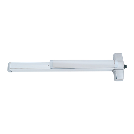
Rim Exit Device
Please give these instructions to building owner after device is installed
XP98/XP99
Devices covered by these instructions:
XP98/XP99 Rim Exit Device
XP98-F/XP99-F (Fire) Rim Exit Device
CDXP98/CDXP99 (Cylinder Dogging) Rim Exit Device
Special tools needed:
Taps: #10-24, 1/4"-20
Drill bits: #7, #25, 1/8", 1/4",
5/16", 3/8", 13/32"
Index:
• Screw chart ............................ 2
• Preparation chart .................... 3
• Device installation ................ 4-6
• Retrofit installation .................. 7
• Hex dogging information ......... 8
• CD (cylinder dogging) ............. 9
• 954 strike installation ............ 10
Installation Instructions
.............. 10
Advertisement

Related Manuals for Von Duprin XP98


Summary of Contents for Von Duprin XP98
-
Page 1: Table Of Contents
Rim Exit Device Installation Instructions Devices covered by these instructions: XP98/XP99 Rim Exit Device XP98-F/XP99-F (Fire) Rim Exit Device CDXP98/CDXP99 (Cylinder Dogging) Rim Exit Device Please give these instructions to building owner after device is installed Index: Special tools needed: •... -
Page 2: Screw Chart
SCREW CHART 909 Strike 1/4”-20 X 3/4” (3 qty) Metal frame Wood frame #14 X 1-1/2” Wood screw (3 qty) SCREW CHART 954 Strike Metal frame 1/4”-20 X 3/4” (6 qty) Surface mount or #10-24 X 1” (4 qty) Sex bolts (1-3/4” door) Sex bolts (2-1/4”... -
Page 3: Preparation Chart
Center case - 2 support holes #25 Drill #10-24 tap RHR shown (LHR opposite) 1/8” Drill pilot 1” deep For XP98-F/XP99-F (fire) wood door #825 Sex bolts (2) required Door cut-outs 1/16” 3/8” Drill thru Outside cylinder applications:... -
Page 4: Device Installation
DEVICE INSTALLATION Note: For retrofit applications where an existing 98/99 Rim device is being replaced, see “Retrofit Installation” on page 7. Draw horizontal device and Align strike on C and mark strike center line (C ). the two outer slots. 909 Strike RHR Shown (LHR opposite) - Page 5 Prepare lock side of door If Necessary, Remove NL Drive Screw for device and trim. NL drive screw See “Preparation Chart” on page 3 for Factory installed on drill, tap, and cut-out information back of center case See trim instructions for pull side door preparation.
- Page 6 IMPORTANT! When properly adjusted, secure Verify gap between latch bolt and strike with additional screw(s). strike and adjust strike as needed. 909 Strike Strike MUST have some gap #7 Drill 1/4”-20 tap Locate hole at center of slot Strike plate 954 Strike (no more than 3/16”) #7 Drill...
-
Page 7: Retrofit Installation
C. Mark and prepare 2 outer holes for 1/4”-20 and install screws. CAUTION 909 strike Locking Old 299/299F or 499F strike cannot be used plate with XP98/99 device. Strike must be removed and replaced with new strike. Old strike Replace with 299/299F 499F 954*... -
Page 8: Hex Dogging Information
HEX DOGGING INFORMATION To undog exit device: To dog exit device: Note: Panic devices are shipped dogged Note: Dogging is recommended during times of (pushbar down). high traffic through door. 1. To undog device, place hex key in hole as 1. -
Page 9: Cd (Cylinder Dogging)
CD (CYLINDER DOGGING) (DO NOT USE ON FIRE RATED DEVICE) 1. Remove mortise cylinder cam and reinstall in reverse (Figure 1). Std. mortise cylinder 2. Insert key and rotate cam to install the cylinder to the cover plate (Figure 2). 3. -
Page 10: Cut Device
CUT DEVICE Measure amount to cut off device. Tape and mark area being cut. Remove anti-rattle clip 1-1/2” minimum clearance (with endcap removed) Tape Cover plate (flush to end of channel) Note If 5/8” diameter wire access hole Pushbar has been predrilled in door, cut device 5/16”... - Page 12 © Allegion 2016 Customer Service Printed in U.S.A. 911000-00 Rev. 05/16-e 1-877-671-7011 www.allegion.com/us...
Need help?
Do you have a question about the XP98 and is the answer not in the manual?
Questions and answers