Table of Contents
Advertisement
Advertisement
Table of Contents

Related Manuals for ABB REF615 ANSI 5.0 FP1


Summary of Contents for ABB REF615 ANSI 5.0 FP1
- Page 1 — P R O D U C T G U I D E REF615 ANSI 5.0 FP1 Feeder protection and control...
-
Page 2: Table Of Contents
19. Inputs and outputs 2. Standard configurations 20. Station communication 3. Protection functions 20. Technical data 4. Application 21. Local HMI 5. Supported ABB 22. Mounting methods solutions 23. Relay case and plug-in 6. Control unit 7. Measurements 24. Selection and ordering data 8. -
Page 3: Description
Control Relay Manager PCM600. Further, or without distributed power generation. REF615 is the application configuration functionality of a member of ABB’s Relion® product family and part PCM600 supports the creation of multi-layer logic of its 615 protection and control product series. - Page 4 R E F 6 1 5 A N S I 5 . 0 F P 1 F E E D E R P R OT E C T I O N A N D C O N T R O L —...
- Page 5 — Figure 2. Functionality overview for standard configuration F Δ Υ or Δ REF615 V5.0 FP1 ANSI Func Appl F 50P-3 46-1 46-2 46PD 49F-1 INR-1 BF-1 51P-1 51P-2 50P-1 27-1 59-1 51N-1 51N-1 51N-2 50N-1 59-2 27-2 21YN- 21YN- 21YN- 50G-1 67NIEF...
- Page 6 R E F 6 1 5 A N S I 5 . 0 F P 1 F E E D E R P R OT E C T I O N A N D C O N T R O L —...
- Page 7 — Figure 4. Functionality overview for standard configuration N Δ Υ or Δ REF615 V5.0 FP1 ANSI Func Appl N 50P-3 51P-1 46-1 46-2 46PD 49F-1 INR-1 27-1 32Q- 32U-1 32U-2 51P-2 50P-1 50P-2 BF-1 27-2 78V-1 32R/ 32R/ 59-1 27-3 32O-1 32O-2...
- Page 8 R E F 6 1 5 A N S I 5 . 0 F P 1 F E E D E R P R OT E C T I O N A N D C O N T R O L —...
- Page 9 — Table 1. Standard configurations Description Std. conf. Non-directional overcurrent and ground fault protection and circuit-breaker condition monitoring (RTD option) Directional overcurrent and ground fault protection, voltage-based protection and measurements, and circuitbreaker condition monitoring (RTD option), and voltage remanent protection Directional and non-directional overcurrent and ground fault protection with multifrequency neutral admittance, voltage, frequency and power based protection and measurements, and circuit-breaker condition monitoring (sensor inputs, optional power quality, fault locator, interconnetion protection and synchro-check and voltage remanent protection with IEC 61850-9-2 LE)
- Page 10 R E F 6 1 5 A N S I 5 . 0 F P 1 F E E D E R P R OT E C T I O N A N D C O N T R O L —...
- Page 11 — Table 2. Supported functions, continued Function IEC 61850 ANSI High-impedance differential protection for phase C HICPDIF (19) Circuit breaker failure (B1) protection CCBRBRF 50BF (B2) Three-phase inrush detector INRPHAR Switch onto fault CBPSOF SOTF Master trip TRPPTRC 86/94 (22) (22) (22) (22)
- Page 12 R E F 6 1 5 A N S I 5 . 0 F P 1 F E E D E R P R OT E C T I O N A N D C O N T R O L —...
- Page 13 — Table 2. Supported functions, continued () = optional 1) One of the following can be ordered as an option; Admittance based E/F, Wattmetric based E/F or Harmonics based E/F. The option is an addition to the existing E/F of the original configuration.
- Page 14 R E F 6 1 5 A N S I 5 . 0 F P 1 F E E D E R P R OT E C T I O N A N D C O N T R O L 3.
-
Page 15: Application
The sensor inputs also enable the use of the relay in compact medium voltage switchgears, such The standard configuration D offer non-directional as ABB’s ReliaGear® ND Digital, Advance® Digital, ground-fault protection for outgoing feeders and SafeGear® Digital, eliminating the need of ded- equipped with phase current transformers. - Page 16 R E F 6 1 5 A N S I 5 . 0 F P 1 F E E D E R P R OT E C T I O N A N D C O N T R O L Completed with the optional synchrocheck func- In addition to directional ground-fault protection, tion, voltage remant protection, and process bus...
- Page 17 — Figure 6 shows a substation example with overcur- Figure 6. Substation example with overcur- rent and ground-fault protection using the stan- rent and ground-fault dard configuration D. Additionally voltage and fre- protection using the standard configuration D quency based protection is used with standard configuration F.
- Page 18 R E F 6 1 5 A N S I 5 . 0 F P 1 F E E D E R P R OT E C T I O N A N D C O N T R O L —...
- Page 19 — Application example with single busbar switchgear Figure 8. Application ex- ample with single busbar arrangement is shown in Figure 8. Current sensors switchgear arrangement (Rogowski coil) and voltage sensors (voltage di- vider) are used for the measurements in standard configurations L.
- Page 20 R E F 6 1 5 A N S I 5 . 0 F P 1 F E E D E R P R OT E C T I O N A N D C O N T R O L —...
- Page 21 — Figure 10 illustrates an application example of sin- cables. Additionally, an optional autoreclosing Figure 10. Application example of single busbar gle busbar switchgear using the most comprehen- function is used for the feeders with overhead line. switchgear using the sive standard configuration N and P.
- Page 22 R E F 6 1 5 A N S I 5 . 0 F P 1 F E E D E R P R OT E C T I O N A N D C O N T R O L —...
- Page 23 — In the application example in Figure 12, single bus- Figure 12. Application example of busbar bar switchgear has been arranged into two bus differential protection sections separated with bus coupler. Standard con- covering two zones using standard configuration N figuration N is used with high-impedance differen- tial protection for busbar and covering two zones with two protection relays.
-
Page 24: Supported Abb Solutions
To on both real-time and historical values. A better un- facilitate the system engineering, ABB's relays are derstanding of the process dynamics is achieved by supplied with connectivity packages. The connec-... -
Page 25: Control
— Figure 13. ABB power system example using Relion relays, COM600S and MicroSCADA Pro/ System 800xA MicroSCADA Pro/ System 800xA Utility: IEC 60870-5-104 Industry: OPC COM600F COM600F Web HMI Web HMI Ethernet switch PCM600 Ethernet switch PCM600 Analog and binary horizontal... -
Page 26: Measurements
R E F 6 1 5 A N S I 5 . 0 F P 1 F E E D E R P R OT E C T I O N A N D C O N T R O L 7. -
Page 27: Event Log
11. Event log 13. Condition monitoring To collect sequence-of-events information, the re- The condition monitoring functions of the relay lay has a nonvolatile memory capable of storing constantly monitor the performance and the condi- 1024 events with the associated time stamps. The tion of the circuit breaker. -
Page 28: Self-Supervision
R E F 6 1 5 A N S I 5 . 0 F P 1 F E E D E R P R OT E C T I O N A N D C O N T R O L 15. - Page 29 — Table 4. Input/output overview Std. Conf. Order code digit Analog channels Binary channels Combi- sensor BI 4 PO + 9 SO AC/AD 4 PO + 5 SO + 3 HSO 4 PO + 6 SO FC/FD 4 PO + 2 SO + 3 HSO 4 PO + 6 SO AE/AF...
-
Page 30: Station Communication
R E F 6 1 5 A N S I 5 . 0 F P 1 F E E D E R P R OT E C T I O N A N D C O N T R O L 20. - Page 31 — HSR applies the PRP principle of parallel operation frame it sent, the sender node discards the frame Figure 15. Parallel redundancy proto- to a single ring. For each message sent, the node to avoid loops. The HSR ring with 615 series relays col (PRP) solution sends two frames, one through each port.
- Page 32 R E F 6 1 5 A N S I 5 . 0 F P 1 F E E D E R P R OT E C T I O N A N D C O N T R O L —...
- Page 33 All communication connectors, except for the front When the relay uses the RS-485 bus for the serial port connector, are placed on integrated optional communication, both two- and four wire connec- communication modules. The relay can be con- tions are supported. Termination and pull-up/down nected to Ethernet-based communication systems resistors can be configured with jumpers on the via the RJ-45 connector (100Base-TX) or the fiber...
- Page 34 R E F 6 1 5 A N S I 5 . 0 F P 1 F E E D E R P R OT E C T I O N A N D C O N T R O L Required accuracy of grandmaster clock is +/-1 μs.
-
Page 35: Technical Data
20. Technical data — Table 6. Dimensions Description Value frame 177 mm Width case 164 mm frame 177 mm (4U) Height case 160 mm Depth case 201 mm (153 + 48mm) complete protection relay 4.1 kg Weight plug-in unit only 2.1 kg —... - Page 36 R E F 6 1 5 A N S I 5 . 0 F P 1 F E E D E R P R OT E C T I O N A N D C O N T R O L —...
- Page 37 — Table 14. Double-pole power output relays with TCS function Description Value Rated voltage 250 V AC/DC Continuous contact carry Make and carry for 3.0 s 15 A Make and carry for 0.5 s 30 A Breaking capacity when the control-circuit time constant L/R<40 ms, at 48/110/220 V DC (two contacts connected in series) 5 A/3 A/1 A Minimum contact load...
- Page 38 R E F 6 1 5 A N S I 5 . 0 F P 1 F E E D E R P R OT E C T I O N A N D C O N T R O L —...
- Page 39 — Table 23. Electromagnetic compatibility tests (continued) Description Type test value Reference Radio frequency interference test 10 V (rms) IEC 61000-4-6 f = 150 kHz...80 MHz IEC 60255-26, class III 10 V/m (rms) IEC 61000-4-3 f = 80...2700 MHz IEC 60255-26, class III 10 V/m ENV 50204 f = 900 MHz...
- Page 40 R E F 6 1 5 A N S I 5 . 0 F P 1 F E E D E R P R OT E C T I O N A N D C O N T R O L —...
- Page 41 Protection functions — Table 30. Three-phase non-directional overcurrent protection (PHxPTOC) Characteristic Value Depending on the frequency of the measured current: fn ±2 Hz PHLPTOC ±1.5% of the set value or ±0.002 x I ±1.5% of set value or ±0.002 x I Operation accuracy PHHPTOC (at currents in the range of 0.1…10 x I...
- Page 42 R E F 6 1 5 A N S I 5 . 0 F P 1 F E E D E R P R OT E C T I O N A N D C O N T R O L —...
- Page 43 — Table 34. Three-phase non-directional overcurrent protection (PHxPTOC) Characteristic Value Depending on the frequency of the measured current: fn ±2 Hz EFLPTOC ±1.5% of the set value or ±0.002 x I ±1.5% of set value or ±0.002 x I Operation accuracy EFHPTOC (at currents in the range of 0.1…10 x I ±5.0% of the set value...
- Page 44 R E F 6 1 5 A N S I 5 . 0 F P 1 F E E D E R P R OT E C T I O N A N D C O N T R O L —...
- Page 45 — Table 38. Admittance-based earth-fault protection (EFPADM) Characteristic Value At the frequency f = f Operation accuracy ±1.0% or ±0.01 mS (In range of 0.5...100 mS) Minimum Typical Maximum Start time 1) 2) 56 ms 60 ms 64 ms Reset time 40 ms Operate time accuracy i ±1.0% of the set value or ±20 ms...
- Page 46 R E F 6 1 5 A N S I 5 . 0 F P 1 F E E D E R P R OT E C T I O N A N D C O N T R O L —...
- Page 47 — Table 45. Harmonics-based earth-fault protection (HAEFPTOC) main settings Parameter Function Value (range) Step Start value HAEFPTOC 0.05...5.00 × I 0.01 HAEFPTOC Time multiplier 0.05...15.00 0.01 Operate delay time HAEFPTOC 100...200000 ms Definite or inverse time Operating curve type HAEFPTOC Curve type: 1, 2, 3, 4, 5, 6, 7, 8, 9, 10, 11, 12, 13, 14, 15, 17, 18, 19 Minimum operate time HAEFPTOC...
- Page 48 R E F 6 1 5 A N S I 5 . 0 F P 1 F E E D E R P R OT E C T I O N A N D C O N T R O L —...
- Page 49 — Table 53. Three-phase undervoltage protection (PHPTUV) Characteristic Value Depending on the frequency of the measured current: f ±2 Hz Operation accuracy ±1.5% of the set value or ±0.002 x U Minimum Typical Maximum Start time 1) 2) = 0.9 x set Start value 62 ms 66 ms 70 ms...
- Page 50 R E F 6 1 5 A N S I 5 . 0 F P 1 F E E D E R P R OT E C T I O N A N D C O N T R O L —...
- Page 51 — Table 62. Frequency protection (FRPFRQ) main settings Parameter Function Value (range) Step 1 = Freq< 2 = Freq> 3 = df/dt Operation mode FRPFRQ 4 = Freq< + df/dt 5 = Freq> + df/dt 6 = Freq< OR df/dt 7 = Freq>...
- Page 52 R E F 6 1 5 A N S I 5 . 0 F P 1 F E E D E R P R OT E C T I O N A N D C O N T R O L —...
- Page 53 — Table 72. Switch onto fault (CBPSOF) main settings Parameter Function Value (range) Step SOTF reset time CBPSOF 0...60000 ms — Table 73. Arc protection (ARCSARC) Characteristic Value Operation accuracy Depending on the frequency of the measured current: f ±2 Hz Minimum Typical Maximum...
- Page 54 R E F 6 1 5 A N S I 5 . 0 F P 1 F E E D E R P R OT E C T I O N A N D C O N T R O L —...
- Page 55 — Table 83. Multifrequency admittance-based earth-fault protection (MFADPSDE) Characteristic Value Depending on the frequency of the measured voltage: ±2 Hz Operation accuracy ±1.5% of the set value or ±0.002 × U Start time Typically 35 ms Reset time Typically 40 ms Operate time accuracy ±1.0% of the set value of ±20 ms 1) Includes the delay of the signal output contact, results based on statistical distribution of 1000 measurements...
- Page 56 R E F 6 1 5 A N S I 5 . 0 F P 1 F E E D E R P R OT E C T I O N A N D C O N T R O L Interconnection functions —...
- Page 57 — Table 89. Low-voltage ride-through protection (LVRTPTUV) main settings Parameter Function Value (range) Step Voltage start value LVRTPTUV 0.05...1.20 × U 0.01 4 = Exactly 1 of 3 Num of start phases LVRTPTUV 5 = Exactly 2 of 3 6 = Exactly 3 of 3 1 = Highest Ph-to-E 2 = Lowest Ph-to-E Voltage selection...
- Page 58 R E F 6 1 5 A N S I 5 . 0 F P 1 F E E D E R P R OT E C T I O N A N D C O N T R O L Power quality functions —...
- Page 59 Control functions — Table 94. Autoreclosing (DARREC) Characteristic Value Operate time accuracy ±1.0% of the set value or ±20 ms — Table 95. Synchronism and energizing check (SECRSYN) Characteristic Value Depending on the frequency of the voltage measured: f ±1 Hz Voltage: ±3.0% of the set value or ±0.01 ×...
- Page 60 R E F 6 1 5 A N S I 5 . 0 F P 1 F E E D E R P R OT E C T I O N A N D C O N T R O L Condition monitoring and supervision functions —...
- Page 61 — Table 102. Fuse failure supervision (SEQSPVC) Characteristic Value Operate time1) NPS function = 1.1 × set Neg Seq voltage <33 ms Fault = 5.0 × set Neg Seq voltage <18 ms Fault Delta function ΔU = 1.1 × set Voltage change rate <33 ms ΔU = 2.0 ×...
- Page 62 R E F 6 1 5 A N S I 5 . 0 F P 1 F E E D E R P R OT E C T I O N A N D C O N T R O L Measurement functions —...
- Page 63 — Table 110. Three-page power and energy measurements (SPEMMXU and PEMMXU) Characteristic Value At all three currents in range 0.10…1.20 × I At all three voltages in range 0.50…1.15 × U At the frequency f ±1 Hz Operation accuracy ±1.5% for apparent power S ±1.5% for active power P and active energy ±1.5% for reactive power Q and reactive energy ±0.015 for power factor...
- Page 64 R E F 6 1 5 A N S I 5 . 0 F P 1 F E E D E R P R OT E C T I O N A N D C O N T R O L Other functions —...
-
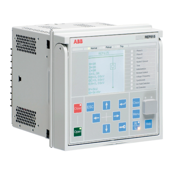
Page 65: Local Hmi
21. Local HMI diagram. The SLD view can also be accessed using The relay is available with two optional displays, a the Web browser-based user interface. The default large one and a small one. The large display is SLD can be modified according to user require- suited for relay installations where the front panel ments by using the Graphical Display Editor in user interface is frequently used and a single line... -
Page 66: Mounting Methods
CT secondary circuits when a relay unit is with- Order Number Tool, supports order code creation drawn from its case. The relay case is further pro- for ABB Distribution Automation IEC products with vided with a mechanical coding system preventing emphasis on, but not exclusively for, the Relion the current measuring relay units from being in- product family. -
Page 67: 25. Accessories And Ordering Data
25. Accessories and ordering data — Table 115. Cables Item Order number Optical sensor for arc protection, cable length 1.5 m 1MRS120534-1.5 Optical sensor for arc protection, cable length 3.0 m 1MRS120534-3 Optical sensor for arc protection, cable length 5.0 m 1MRS120534-5 Optical sensor for arc protection, cable length 7.0 m 1MRS120534-7... -
Page 68: Tools
R E F 6 1 5 A N S I 5 . 0 F P 1 F E E D E R P R OT E C T I O N A N D C O N T R O L 26. -
Page 69: Cyber Security
— Table 118. Supported functions Function Web HMI PCM600 Relay parameter setting • • Saving of relay parameter settings in the relay • • Signal monitoring • • Disturbance recorder handling • • Alarm LED viewing • • Access control management •... -
Page 70: Terminal Diagrams
R E F 6 1 5 A N S I 5 . 0 F P 1 F E E D E R P R OT E C T I O N A N D C O N T R O L 28. - Page 71 — Figure 23. Terminal diagram of standard configuration F...
- Page 72 R E F 6 1 5 A N S I 5 . 0 F P 1 F E E D E R P R OT E C T I O N A N D C O N T R O L —...
- Page 73 — Figure 25. Terminal diagram of standard configuration N The protection relay features an automatic mechanism in the CT connector when plug-in unit is detached...
- Page 74 R E F 6 1 5 A N S I 5 . 0 F P 1 F E E D E R P R OT E C T I O N A N D C O N T R O L —...
-
Page 75: Certificates
1A “Trip” for distribution bays (transfer time <10 msec) as defined in IEC 61850-5”. 31. References The www.abb.com/substationautomation portal provides information on the entire range of distri- bution automation products and services. The latest relevant information on the REF615 pro- tection and control relay is found on the product page. -
Page 76: Functions, Codes And Symbols
R E F 6 1 5 A N S I 5 . 0 F P 1 F E E D E R P R OT E C T I O N A N D C O N T R O L 32. - Page 77 — Table 119. Functions included in the relay (continued) Function IEC 61850 ANSI FRPFRQ1 81 (1) FRPFRQ2 81 (2) FRPFRQ3 81 (3) Frequency protection FRPFRQ4 81 (4) FRPFRQ5 81 (5) FRPFRQ6 81 (6) Three-phase thermal protection for feeders, cables and distribution transformers T1PTTR1 49F (1)
- Page 78 R E F 6 1 5 A N S I 5 . 0 F P 1 F E E D E R P R OT E C T I O N A N D C O N T R O L —...
-
Page 79: Document Revision History
Function IEC 61850 ANSI Measurement IEC 61850-9-2 LE sampled value receiving (voltage sharing) SMVRCV SMVRCV Other TPGAPC1 TP (1) TPGAPC2 TP (2) Minimum pulse timer (2 pcs) TPGAPC3 TP (3) TPGAPC4 TP (4) Minimum pulse timer (2 pcs, second resolution) TPSGAPC1 TPS (1) Minimum pulse timer (2 pcs, minute resolution) - Page 80 — ABB Inc. 4300 Coral Ridge Drive Coral Springs, Florida 33065 Phone: +1 954 752 6700 abb.com/mediumvoltage abb.com/substationautomation © Copyright 2017 ABB. All rights reserved. Specifications subject to change without notice.
Need help?
Do you have a question about the REF615 ANSI 5.0 FP1 and is the answer not in the manual?
Questions and answers