Advertisement
Table of Contents
- 1 Table of Contents
- 2 Instrument Care
- 3 Features
- 4 Measurement Parameters
- 5 Specifications
- 6 Controls and Functions
- 7 Lcd Display Description
- 8 Preparation for Use
- 9 Calibration Procedure
- 10 Measurement Procedure
- 11 Setting the Current Time and Date
- 12 Store Record Data Operation
- 13 Output Connectors
- 14 Software Installation and Operation
- Download this manual
Advertisement
Table of Contents

Subscribe to Our Youtube Channel
Related Manuals for TES TES-1353S


Summary of Contents for TES TES-1353S
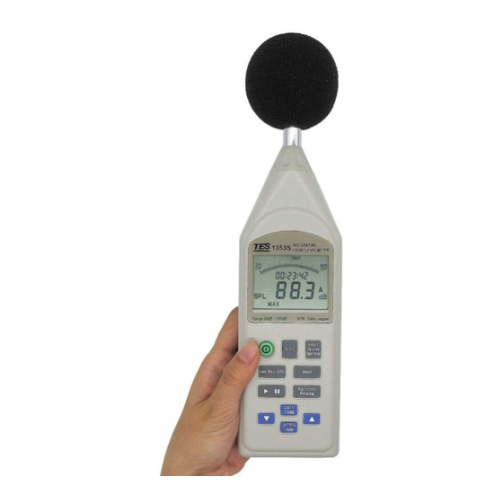
- Page 1 INTEGRATING Sound Level Meter TES-1353S INSTRUCTION MANUAL ※ Enclosed CD : Software & Protocol Inside. Leq SEL SPL RECORD ERASE DATE TIME INTEG TIME TES ELECTRICAL ELECTRONIC CORP.
-
Page 2: Table Of Contents
9. MEASUREMENT PROCEDURE..........15 10. SETTING THE CURRENT TIME AND DATE....... 17 11. STORE RECORD DATA OPERATION......... 18 12. OUTPUT CONNECTORS ............ 22 13. SOFTWARE INSTALLATION AND OPERATION ....23 ※ Copyright © 2013 TES Electrical Electronic Corp. All rights reserved. -
Page 3: Instrument Care
1. INSTRUMENT CARE Do not attempt to remove the mesh cover from the microphone as this will cause damage and affect the accuracy of the instrument. Protect the instrument from impact. Do not drop it or subject it to rough handling. Transport it in the supplied carrying case. -
Page 4: Measurement Parameters
3. MEASUREMENT PARAMETERS The following parameters are used on the instrument. A → “A” frequency weighting sound pressure level C → “C” frequency weighting sound pressure level FAST → Fast time weighting SLOW → Slow time weighting IMP → Impulse time weighting SPL →... - Page 5 Peak Hold sound level PH A or PH C Percentile sound level L : 05 A or L : 05 C L : 10 A or L : 10 C L : 50 A or L : 50 C L : 90 A or L : 90 C L : 95 A or L : 95 C •...
- Page 6 RANGE: 40 – 100 dB. Test starting point 74 dB for all weightings and frequencies except 31.5Hz A-weighted, for which the starting point is 54 dB. FREQUENCY L.O.R. L.O.R WEIGHTING WEIGHTING 31.5 40.0 – 60.6 40.0 – 97.0 1000 40.0 – 100.0 40.0 –...
- Page 7 Reference incidence direction: Perpendicular to the front of the microphone diaphragm. • Calibration: Acoustic using calibrator TES-1356 or equivalent. Calibration check frequency is 1000Hz. Nominal calibration level for the free field: 94.1dB Nominal calibration level for the diffuse field: 94.0dB •...
- Page 8 Outputs • AC output (using selected frequency weighting) Output voltage: 2Vrms (at full-scale of the range) Output impedance: 5k Ω Load impedance: ≧ 1M Ω • DC output Output voltage: 10mV/dB Output impedance: 5k Ω Load impedance: ≧ 1M Ω •...
- Page 9 Weight (including battery): Approx. 380g Supplied accessories: Instruction manual, Batteries, Adjustment screwdriver, CD software, Windscreen, USB connecting cable, 3.5φ plug, Carrying case. Optional equipment (Not supplied): AC adaptor, Sound calibrator TES-1356, Portable thermal printer, Thermal printer connecting cable, Microphone extension cable.
-
Page 10: Controls And Functions
5. CONTROLS AND FUNCTIONS 1/2-inch microphone 2. Display: The LCD shows the sound level as a numeric value and a bar graph. The display also shows the operation mode of the instrument, the selected measurement parameters and warning indications. Button: Press to turn the instrument on and off. Leq SEL SPL button : Press this button the following parameters are monitored during integrating measurement and can be viewed selectively :... - Page 11 button : Press to start ( “ ” measurement symbol) or pause ( “ ” pause symbol) the integrating sound level measurement (including the various processing functions) or the data recording. When the measurement period is completed, the ( “ ” end symbol) indication is shown on the display.
-
Page 12: Lcd Display Description
INTEG TIME button : Select the default measurement time : Press this button one time enter to integrating measurement time select mode, use “ ” buttons to select →1sec→3sec→10sec new manual setting time→ --:--:-- the measurement time, →30sec→1min→5min →8min→10min→15min→30min→1hour→8hour→24hour. Setting to desired measurement time : Press this button 2 seconds enter to other desired integrating measurement time setting mode, the setting range from 1 second to 100 hours. - Page 13 Sound level range indicator (5 ranges): 30–90dB, 40–100dB, 50–110dB, 60–120dB and 70–130dB Bar graph shows the current sound level (1dB resolution). Date/time and elapsed time indicator : During integrating this indicator shows the elapsed time in seconds. During viewed the peak hold sound level this indicator the “PH”. During viewed the percentile tile sound level this indicator shows the L:05, L:10, L:50, L:90 and L:95 parameters.
-
Page 14: Preparation For Use
7. PREPARATION FOR USE Power Supply The instrument can be powered by internal batteries, or for extended operation by an optional external 6V DC supply such as a suitable AC mains adapter or battery pack. Rechargeable batteries may be used in the instrument, but cannot be recharged when fitted as the instrument is not designed to recharge batteries. - Page 15 3. Windscreen When making measurements outdoors in strong winds or when measuring air conditioning equipment or similar, wind noise and strong air movements at the microphone can cause measurement errors. Such effect can be reduced by using the windscreen. 4. Tripod Mounting For long-term measurements, the instrument may be mounted on a standard camera tripod using the integral ¼”...
-
Page 16: Calibration Procedure
Most national standards recommend that you calibrate your sound level meter before each set of measurements and check the calibration after each set. The procedure to check/adjust the displayed sound level in response to acoustic calibrator types TES-1356 or equivalent is as follows: 1. Turn off the sound calibrator. 94dB... -
Page 17: Measurement Procedure
9. MEASUREMENT PROCEDURE 9-1 Sound level measurement 1. Press the button to turn on the instrument. The initial state depends on the condition the instrument was in before it was last turned off. A / C 2. Press the “ ”... - Page 18 4. Press buttons to select desired level range. Choose a setting in which the bar graph indication registers to about the middle of the range. If the “OVER” or “UNDER” indicators light up frequently, change the level range setting. 5. Setting the integrating measurement time. INTEG TIME Press...
-
Page 19: Setting The Current Time And Date
Leq SEL SPL 7. When the measurement is pause or completed, press button to cycle switch displaying the following measurement result. Leq : Equivalent continuous sound level with start measurement time. SEL : Sound exposure level with terminate measurement time. SPL MAX : Maximum sound level with time. -
Page 20: Store Record Data Operation
11. STORE RECORD DATA OPERATION The meter incorporates a memory which can be used to store measurement data. The maximum has 200M data capacity can be split up to 255 blocks record. The record sampling interval time has been fixed at 1 second. The record data has two method, with or without preset start time for record data. - Page 21 2. During measurement, press button can be used to pause and resume the measurement. During pause the pause symbol “ ” is shown and the “ REC ” symbol stop flash. When wishing to terminate the measurement earlier, press enter to pause mode.
- Page 22 In the pause mode, press button 2 seconds the recorded blocks number (1 to 255) display one time and exit record mode, the pause symbol “ ” and “ REC ” symbol are disappeared. 5. When memory is filled (200M data or 255 blocks is full used), the “ REC FULL” symbol is displayed.
- Page 23 SPL MAX : Maximum sound level with time. SPL MIN : Minimum sound level with time. L:05 : 5% percentile sound level L:10 : 10% percentile sound level L:50 : 50% percentile sound level L:90 : 90% percentile sound level L:95 : 95% percentile sound level SPL : Current sound level with current time.
-
Page 24: Output Connectors
12. PRINTING DATA (OPTIONAL – PROVA 300XP PRINTER) 1. Using thermal printer cable connecting the meter and the printer. 2. Turn on the printer. 3. Setting the meter printing interval time. Press button turn off the meter. INTEG TIME Press and hold down button then turn on the meter, enter to sampling interval time setting mode, the “... -
Page 25: Software Installation And Operation
13-3 Alarm output Setting the sound level alarm high limit 1. Press button turn off the meter. Leq SEL SPL 2. Press and hold down button then turn on the meter, enter to sound level high limit setting mode, the “ALARM” symbol is displayed. 3. - Page 26 TES ELECTRICAL ELECTRONIC CORP. 7F, No. 31, Lane 513, Rui Guang Road, Neihu Dist. Taipei. Taiwan, R. O. C. Tel : (02) 2799-3660 Fax : 886-2-2799-5099 E-Mail : tes@ms9.hinet.net http://www.tes.com.tw Mar-2013...
Need help?
Do you have a question about the TES-1353S and is the answer not in the manual?
Questions and answers
I don't have the Cd to download measurements of TES TES-1353S