
Subscribe to Our Youtube Channel
Related Manuals for TES TES-133


Summary of Contents for TES TES-133
- Page 1 Luminous Flux Meter TES-133 INSTRUCTION MANUAL ※ ※ ※ ※ Enclosed CD : Software & Protocol Inside. ZERO RATIO ZERO MAX MIN TES ELECTRICAL ELECTRONIC CORP.
-
Page 2: Table Of Contents
5-14 To Disable Auto Power off Function ........21 6. BATTERY CHECK-UP & & & & REPLACEMENT ........21 7. SPECTRAL SENSITIVITY CHARACTERISTIC......21 8. MAINTENANCE................22 9. RS-232 INTERFACE, SOFTWARE INSTALLATION AND OPERATION...................22 ※ ※ ※ ※ Copyright © 2009 TES Electrical Electronic Corp. All rights reserved. -
Page 3: Introduction
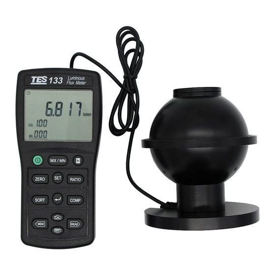
1. INTRODUCTION The meter is an easy-to-use, precision photometric meter designed for use in the field, laboratory, or production floor. The meter measures luminous flux from source such as LED’s, small lamps, and fibre-illuminators. The meter features a 75mm diameter integrating shpere that collects the total light entering the sphere measurement port. -
Page 4: Features
2. FEATURES Easy-to-read 4 digit LCD display. Spectral Sensitivity close to CIE photopic Curve. Measuring Level Range: 0.05 to 7000 lumens, Autoranging 4 steps. Accurate and Instant response. Data Hold function. Auto Data Hold function. Data memory and read function. Maximum / Minimum function. - Page 5 • Spectral Accuracy : CIE Vλ function f ’ ≦ 6% • Integrating Sphere : Diameter : 75 mm Material : BaSO Sample Port : 25 mm dia. • Photo Detector : One silicone photo diode and spectral response filter. •...
-
Page 6: Parts & Controls
4. PARTS & CONTROLS 4-1 Description of Parts & Control keys ZERO RATIO ZERO MAX MIN 1. LCD Display : 4 digit display with a maximum of 9999 readings and the indicating signs of measured values, unit function symbols and decimal points etc. are displayed. Power Control key :... - Page 7 Data-Hold key : 1 Press key to hold data, the D-H annunciator is displayed, press this key again to exit this mode. 2 Press key for 3 seconds to enter the auto hold mode, the A-H annunciator is displayed, press key for 3 seconds to exit this mode.
- Page 8 2 Press key first then press key to enter the sort tolerance limits setting mode. key : 1 Exit a setting mode or store the displayed setting. 2 Exit the READ and Auto datalogging mode. key : 1 Press key to enter the comparator mode, the COMP annunciator is displayed, press this key again to exit this mode.
- Page 9 2 Press key for 3 seconds to turn on the RS232 interface. 3 In the reference value setting mode and the comprator value setting mode, press key to move the decimal point right to the desired position. key : 1 In the setting mode press key to increase the setting value.
-
Page 10: Description Of Display
4-2 Description of Display ZERO ZERO RATIO : Auto power off indication. ZERO : Zero mode indication ( φ = φ – φ ZERO RATIO : Zero – Ratio mode indication [RATIO = ( φ – φ )/ ( φ –... - Page 11 SET CAL 1. : Calibration factor setting mode indication (0.01 to 9.99). SET REF 1. lumen : Reference value setting mode indication. MAX : Maximum reading display. MIN : Minimum reading display. MAX MIN : Current reading display. AVG : Manual data memory average value display. COMP : Comparator function on indication.
-
Page 12: Operating Instructions
5. OPERATING INSTRUCTIONS When press key to trun on the meter, the various settings depend on the condition the meter was in before it was last turned off. 5-1 Setting the Calibration Factor Because the meter of the photopic filter is not perfect and small adjustments to the collected radiation profile are needed to improve the meter accuracy when measuring LED’s. -
Page 13: Luminous Flux Measurement
5-2 luminous Flux Measurement 1. Determine an appropriate entry sample port from the port adaptor kit. 2. Press key to turn on the meter. 3. Position the light source at the sample port. If you are measuring LEDs and the meter includes a port adaptor, insert the lens into the aperture as far as it will go. -
Page 14: Maximum & Minimum Recording Measurement
5-3 Maximum & Minimum Recording Measurement 1. Press key to enter the recording mode, the auto power off function will be auto cancelled. 2. Press key to display the Maximum (MAX), Minimum (MIN) and Current (MAX MIN) measured values. 3. Press this key for 3 seconds exit this mode. 5-4 Hold Function Operation A. -
Page 15: Zero Iunction Operation
5-5 Zero Function Operation Used to offset a dark current reading. 1. Press key to store the dark current reading and enter the ZERO mode, the “ZERO” annunciator is displayed. 2. All subsequent reading on the LCD are relative to the previous reading, the LCD will read : φ... - Page 16 B. Use the setting value as the reference value. 1. Setting the reference value. a. Press key first then press key to enter the reference value setting mode, the “ SET REF ” annunciator and the previous reference value are displayed. b.
-
Page 17: Zero-Ratio Function Operation
5-7 ZERO-Ratio Function Operation A. Use the current measured value as the reference value. 1. Press key to store the dark current ( φ ), and subsequently takes a measurement ( φ ), the LCD will read : φ = φ - φ... -
Page 18: Sort Function Operation
B. Use the current reference value 1. Press key to display the reference value ( φ φ φ 2. Press key, the LCD will read : RATIO = φ φ − 3. Press key, the LCD will read : RATIO = φ... -
Page 19: Comparator Setting And Operation
C. Sort Operation 1. Press key to enter the SORT mode, the reference value and the sort tolerance limits is displayed. 2. The sort tolerance limits is divided into ten classes from -10 to -1 and +1 to +10 classes. If the measured value over the tolerance limits, the +OL or -OL will be display. -
Page 20: Manual Data Memory And Read Mode
3. Press ⊳ keys to select the desired decimal point position. 4. Press keys to set the desired High limit value. 5. Press key to enter the comparator Low limit value setting mode. 6. Press ⊳ keys to select the desired decimal point position. 7. -
Page 21: Auto Datalogging Function
3. Press key to display the manual memorized data value of Maximum (MAX), Minimum (MIN) and Average (AVG), if the manual memorized data all are measured in the same mode. 4. Press key to exit this mode. C. To clear the manual memorized data 1. -
Page 22: Rs232 Communication
B. To Enter Auto Datalogging mode 1. Press key until the beeper sound to enter this mode. The “A-M INTV” marks are displayed, when the “A-M” mark is disappear one time, one set of reading is stored to the memory. 2. -
Page 23: To Disable Auto Power Off Function
5-14 To Disable Auto Power off Function The meter enters sleep mode if no key is pressed for approx. 15 minutes. 1. Press key to turn off the meter. 2. Press and hold down key then press key to turn on the meter and the auto power off function will be disabled. -
Page 24: Maintenance
8. MAINTENANCE 1. Do not store the instrument where temperature or humidity is excessively high. 2. Cleaning : Periodically wipe the case with a damp cloth and mild detergent. Do not use abrasives or solvents. Clean and dry as required. 9. - Page 25 TES ELECTRICAL ELECTRONIC CORP. 7F, No. 31, Lane 513, Rui Guang Road, Neihu Dist. Taipei. Taiwan, R. O. C. Tel : (02) 2799-3660 Fax : 886-2-2799-5099 E-Mail : tes@ms9.hinet.net http://www.tes.com.tw Jan-2011-3...
Need help?
Do you have a question about the TES-133 and is the answer not in the manual?
Questions and answers