
Subscribe to Our Youtube Channel
Related Manuals for TES TES-1304


Summary of Contents for TES TES-1304
- Page 1 TYPE - K.J.E.T. PRINTING THERMOMETER TES - 1304 INSTRUCTION MANUAL TES ELECTRICAL ELECTRONIC CORP.
-
Page 2: Table Of Contents
CONTENTS Title Page SAFETY INFORMATION ............1 II. SPECIFICATIONS ..............2 2-1 General Information.............. 2 2-2 Electrical Specifications ............4 III. NAME OF PARTS AND POSITION........5 PRECAUTIONS AND PREPARATIONS FOR MEASUREMENT.. 10 V. OPERATIONAL GUIDE ............11 VI. HOW TO SETUP INTERVAL PRINT........18 VII. -
Page 3: Safety Information
SAFETY INFORMATION Read the following safety information carefully before attempting to operate or service the meter. Use the meter only as specified in this manual; otherwise, the protection provided by the meter may be impaired. Caution when working with voltages above 60V or 24V RMS. -
Page 4: Specifications
II. SPECIFICATIONS 2-1 General Information Display :4 1/2 LCD. LCD Annunciator : Fig-1 T1-T2 , T2 , T1 : Indicating function at channel. MAX, MIN, AVG : Maximum or Minimum or Average of reading Average=1/2(Previous reading+Current reading) K J E T :... - Page 5 or - Over Range Indication : appears. Low Battery Indication : shows up when the battery’s voltage below the operating voltage. Sampling Rate : about 1 time per second Power Requirement : 6pcs 1.5V size AAA alkaline batteries or 9V DC Adaptor /500mA minimum.
-
Page 6: Electrical Specifications
Printer : Thermo-printing type with 16 characters per line using 38mm width plain thermo-paper. Instant printing : press-on printing anytime with 2 line of printing. Interval printing : range from 00:00:03 to 23:59:59, according to interval time, continuous printing, can be set in two ways, stopped in three ways. -
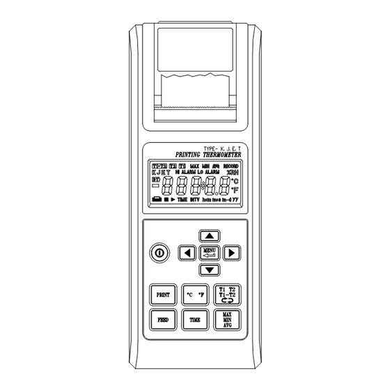
Page 7: Name Of Parts And Position
III. NAME OF PARTS AND POSITION Fig-2 1. LCD : Measured values, unit ,symbols, and decimal points are displayed. 2. POWER : Button for power on/off 3. UNIT : Button for exchanging temperature unit ℃ and ℉ . - Page 8 4. PRINT : Button for start printing currently. The format as below: 1 0 : 5 1 : 1 2 1 1 - 0 2 LINE 1 K - 0 0 2 3 . 0 LINE 2 Line 1 printing time hour: minute: second, month- day, line 2 printing measuring channel, type, value and unit.
- Page 9 9. Hi/ Low Alarm output connector : Fig-4 Pin 1: GND ( external supply low voltage ) Pin 2: VCC ( external supply high voltage ) Pin 3: SYNC( external trigger signal ) Pin4 (HiAlarm) and pin5 (LowAlarm) signals have to be synchronized with pin3.
- Page 10 Note: voltage VCC to GND is 16V Maximum, 5V Minimum. GND ≦ SYNC ≦ VCC Example : Hi Alarm= 1300.5 ℃ Lo Alarm= -50.5 ℃ If LCD reading ≧ 1300.5 ℃ Result : Hi Alarm output reading approx 5V Lo Alarm output reading approx 0V If LCD reading ≦...
- Page 11 10. T measuring : Button for select display methods, T , cycle and normal cycle mode means it will perform T measuring circularly. 11. MENU : Button for start/stop set-up parameters mode. The value will be increased much fast if user do not release the key. 12.
-
Page 12: Precautions And Preparations For Measurement
IV. PRECAUTIONS AND PREPARATIONS FOR MEASUREMENT 1. Before getting use of this instrument, examine it to make sure no shipping damage occurring. Otherwise notify your dealer. 2. Save all packing materials until you are sure that this unit can normally operate. 3. -
Page 13: Operational Guide
V. OPERATIONAL GUIDE A. This meter can be supplied with batteries or 9V Adaptor, If using batteries : Remove the rear cover, and install batteries, pay attention to the polarity of battery socket. If using 9V Adaptor, make sure that it is in good connection to the Adaptor socket of the meter. - Page 14 3. ALARM UNIT ( ℃ / ℉ ):LCD displays as Fig-7 Fig-7 4. FIRST THREE DIGITS IN HI ALARM (-399 〜 399): LCD displays as Fig-8 Example : Hi Alarm = 1234.5℃ Fig-8 5. LAST TWO DIGITS IN HI ALARM (00 〜 99): LCD displays as Fig-9 Fig-9 6.
- Page 15 HOUR OF INTERVAL PRINTING (00 〜 23): LCD displays as Fig-12 Fig-12 9. MINUTE OF INTERVAL PRINTING (00 〜 59): LCD displays as Fig-13 Fig-13 10. SECOND OF INTERVAL PRINTING (00 〜 59): LCD displays as Fig-14 Fig-14 11. HOUR OF START INTERVAL PRINTING TIME (00 〜 23): LCD displays as Fig-15 Fig-15 12.
- Page 16 13. HOUR OF STOP INTERVAL PRINTING TIME (00 〜 23) : LCD displays as Fig-17 Fig-17 14. MINUTE OF STOP INTERVAL PRINTING TIME (00 〜 59): LCD displays as Fig-18 Fig-18 15. FIRST TWO DIGITS OF CALENDAR YEAR (19 〜 29): LCD displays as Fig-19 Fig-19 16.
- Page 17 18. DAY DIGITS OF CALENDAR MONTH-DAY (01 〜 31): LCD displays as Fig-22 Fig-22 19. HOUR DIGITS OF CALENDAR HOUR-MINUTE (00 〜 23): LCD displays as Fig-23 Fig-23 20. MINUTE DIGITS OF CALENDAR HOUR-MINUTE (00 〜 59): LCD displays as Fig-24 Fig-24 21.
- Page 18 If interval printing is enabled by setup parameters, then the printer will action as below : 11 : 54 : 00 11-02 INTV : 00 : 00 : 10 First two lines: Line1: hour:minute:second month-day (start printing time) Line2: interval printing time hour:minute:second Following two lines: Line1: hour:minute:second month-day (interval printing time)
- Page 19 If print button is hold for 2 seconds, it will perform as the following : 12 : 58 : 18 11-02 INTV : 00 : 00 : 10 12 : 58 : 28 11-02 K – 0039.5 ℃ 12 : 58 : 38 11-02 K –...
-
Page 20: How To Setup Interval Print
VI. HOW TO SETUP INTERVAL PRINT 1. Setup interval print with 24 hours limitation. Entering menu mode by pressing MENU button. Enable interval print bit as described in page 11 fig-5 by pressing button. to change menu function to interval print function as described in page 13 fig-12. -
Page 21: Battery Repalcement
4. Sample printing normal printing T1 status : 11 : 53 : 32 02-17 0020.7 ℃ normal printing T2 status : 11 : 54 : 00 02-17 -0020.0 ℃ normal printing T1-T2 status : 11 : 54 : 09 02-17 T12K OL. -
Page 22: Optional Accessory
VIII. OPTIONAL ACCESSORY Type K thermocouple Model Range Tolerances Description 100cm length with tape in -50 ℃ to 200 ℃ ± 2.2 ℃ or ± 0.75 % salvation. TP-K01 Maximum insulating Bead probe -58 ℉ to 392 ℉ ± 3.6 ℉ or ± 0.75 % temperature : 260 ℃... - Page 23 Gamle Drammensvei 107 1363 HØVIK Tel. 22 32 77 20 info@impex.no www.impex.no TES ELECTRICAL ELECTRONIC CORP. 7F, No. 31, Lane 513, Rui Guang Road, Neihu Dist. Taipei, Taiwan, R. O. C. Tel : (02) 2799-3660 Fax : 886-2-2799-5099 E-Mail Address : tes@ms9.hinet.net Home page: http://www.tes.com.tw...
Need help?
Do you have a question about the TES-1304 and is the answer not in the manual?
Questions and answers