Table of Contents
Advertisement
Quick Links
INSTRUCTION MANUAL AND PARTS LIST
DESCRIPTION
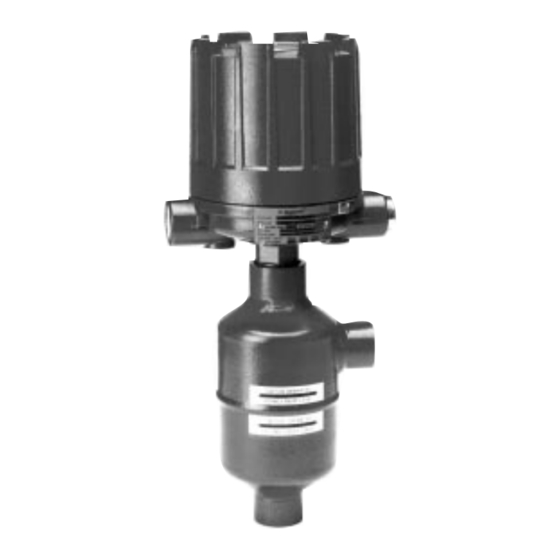
B73 instruments are float operated liquid level controls
designed for external float cage mounting.
These instruments are ideally used for off-on liquid level
control, alarm and safety shut-down service in a wide vari-
ety of applications including large steam-electric generating
stations, oil refineries and chemical processing operations.
The B73 is available with either a carbon steel or stainless
steel float cage and is suitable for service pressure ratings
up to 20.7 bar (300 PSIG) and specific gravity ratings down
to 0.60.
OPERATING PRINCIPLE
A permanent magnet is attached to a pivoted switch mech-
anism. As the float rises following the liquid level, it raises
the magnet attractor into the field of the magnet, which in
turn snaps against the non-magnetic barrier tube, tilting the
switch mechanism. The barrier tube provides a static seal
between the switch mechanism and the float.
Switch
mechanism
Magnet
Enclosing tube
(non-magnetic)
Return spring
Attraction
Swing in
sleeve
position
HL
Figure 1
Switch Tripped
OPERATING CYCLE
As the liquid level rises in the chamber, refer to Figure 1,
the float moves the magnetic attraction sleeve up within the
enclosing tube and into the field of the switch mechanism
magnet. As a result, the magnet is drawn in tightly to the
enclosing tube causing the switch to trip, making or break-
ing an electrical circuit. As the liquid level falls, the float
drops and moves the attraction sleeve out of the magnetic
field, releasing the switch at a predetermined low level.
Refer to Figure 2. The tension spring ensures the return of
the switch in a snap action.
®
Swing out
position
LL
Figure 2
Switch Released
B73 External Cage
Liquid Level Switches
AGENCY APPROVALS
Agency
Approval
CENELEC
EEx d IIC T6, explosion proof
EEx ia IIC T6, intrinsically safe
BASEEFA
Ex d IIC T6
CSA
Non-Hazardous CSA Type 4X
Class I, Div. 2, Groups B, C & D
Class I, Div. 1, Groups C & D
Class II, Div. 1, Groups E, F & G
Class I, Div. 1, Groups B, C & D
Class II, Div. 1, Groups E, F & G
FM
Non-Hazardous NEMA 4X
Class I, Div. 1, Groups C & D
Class II, Div. 1, Groups E, F & G
Class I, Div. 1, Groups B, C & D,
Class II, Div. 1, Groups E, F & G
SAA
Ex d IIC T6 (IP65)
Not available with all switches; Consult factory for proper
model numbers.
Consult factory for proper model numbers.
Advertisement
Table of Contents

Subscribe to Our Youtube Channel
Related Manuals for Magnetrol B73


Summary of Contents for Magnetrol B73
- Page 1 The B73 is available with either a carbon steel or stainless steel float cage and is suitable for service pressure ratings up to 20.7 bar (300 PSIG) and specific gravity ratings down to 0.60.
- Page 2 MODEL IDENTIFICATION A complete B73 switch, consists of 1 code: MATERIALS OF CONSTRUCTION Carbon steel cage with 316 SST float and 400 SST magnetic sleeve. Carbon steel cage with 316 SST float, magnetic sleeve with 316 SST jacket. 316 SST cage and trim and float.
- Page 3 Shutoff PIPING valve Figure 3 shows a typical piping installation of a Magnetrol level switch to a pressure vessel. Reference mark on float chamber should be aligned to correspond with liquid level 305 mm Drain in vessel at which switch control is desired.
- Page 4 Figure 4b PREVENTIVE MAINTENANCE Periodic inspections are a necessary means to keep your Magnetrol level control in good working order. This control is, in reality, a safety device to protect the valuable equipment it serves. Therefore, a systematic program of “Preventive Maintenance”...
- Page 5 3. NEVER attempt to make adjustments or replace switch- es without reading instructions carefully. Certain adjust- ments provided for in Magnetrol controls should not be attempted in the field. When in doubt, consult the facto- 1. NEVER leave switch housing cover off the control ry or your local Magnetrol representative.
- Page 6 Chamber Assembly under items 4 trough 9 assembled. Standard construction kit includes attraction sleeve of IMPORTANT: Many B73 controls are specially tailored type 400 series stainless steel. Stainless steel construc- to meet specific customer specifications and therefore tion kit includes sheathed attraction sleeve used on may contain special parts.
- Page 7 DIMENSIONAL SPECIFICATIONS in mm (inches) OUTLINE DIMENSIONS IN mm (inches) Housing Entry C max D IP 65 (NEMA 4x) 151 (5.93) 109 (4.29) 1" NPT, M20 x 1.5 or PG16 (2 entries - 1 plugged) 459 (18.07) NEMA 7/9 (IP 65) 143 (5.63) 100 (3.94) 1"...
- Page 8 SERVICE POLICY Owners of Magnetrol products may request the return of a control; or, any part of a control for complete rebuilding or replacement. They will be rebuilt or replaced promptly. Magnetrol International will repair or replace the control, at no cost to the purchaser, (or owner) other than transportation cost if: a.
Need help?
Do you have a question about the B73 and is the answer not in the manual?
Questions and answers