Table of Contents
Advertisement
Advertisement
Table of Contents

Subscribe to Our Youtube Channel
Related Manuals for Esse 990 ELX


Summary of Contents for Esse 990 ELX
-
Page 2: Table Of Contents
P.11 STATUTORY WARNINGS. Please read these operating instructions carefully for full information on the safe installation, use and care of your new Esse appliance. This appliance must be correctly installed in accordance with these instructions by a suitably qualified person. - Page 3 Due to our policy of continuous innovation, we reserve the right to adjust or modify our product without prior notification. Do not let children near the oven during use to avoid the danger of burns or injury. Use of the appliance by the elderly or infirm should be supervised.
- Page 4 If the Induction zone glass is cracked or broken the cooker MUST NOT BE CONNECTED and no part of it may be used. Switch off and unplug the appliance to avoid possibility of electric shock. Metallic objects such as knives, forks, spoons and lids should not be placed on the hob surface since they can get hot.
-
Page 5: Technical Data
The cooker data plate is located on the inner door panel of the control compartment. UNPACKAGING YOUR NEW COOKER. Unpack your new Esse Cooker, removing all of the outer packing and accessories from the top and bottom ovens, including protective film on the door liners. At this time please examine the cooker for any damage to the enamel finish and hob glass. -
Page 6: Connecting Cooker
The cooker must be installed in accordance with: All relevant British Standards / Codes of Practice and the relevant Building / IEE regulations Location of the Oven This appliance is designed for domestic cooking only. Use for any other purpose could invalidate any warranty or liability claim. CONNECTING YOUR COOKER For your own safety we recommend that a competent person installs your cooker. - Page 7 Ensure that the power to your ESSE 990 ELX is switched off at the wall. 2. Turn the power to your ESSE 990 ELX on at the wall. The induction hob will run through a start-up routine for a few seconds, during which time all the numerical LEDs will show ‘8’.
-
Page 8: Your Cooker
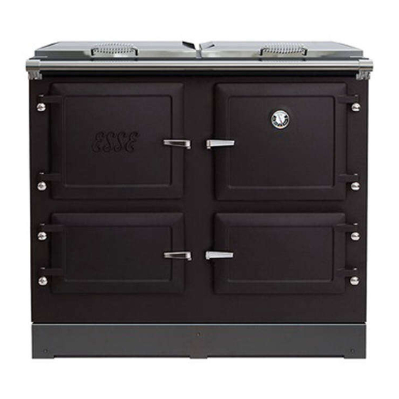
YOUR COOKER. Fig.2 990ELX Cooker SLOW COOK OVEN. CONTROL COMPARTMENT. 3 ZONE INDUCTION. HEAT CONSERVING BOLSTER LIDS. HOTPLATE. TOP OVEN & GRILL. BOTTOM OVEN. Page 8 990ELX-I02-220319... -
Page 9: Spacing & Dimensions
SPACING AND DIMENSIONS. Fig. 3 990ELX Cooker Dimensions All dimensions are in mm Page 9 990ELX-I02-220319... - Page 10 Fig. 4 990ELX Flex Reach The above diagram shows the possible locations where the Flex of the cooker reaches, the plug sockets for the cooker must be within this arc. The cooker is not to be grouted or sealed at the back or sides of the worktop as if any maintenance is required the cooker will have to be pulled away from the wall at the rear.
- Page 11 It is not recommended that any wall cupboards are fitted above the cooker as steam may cause damage. Due to the hand crafted nature of the cooker all dimensions may be ±2mm. Before using your cooker remove plastic protective covers from inner door panels; lift up lids and hinge covers.
-
Page 12: Commissioning Checklist
COMMISSIONING CHECKLIST To assist with any potential guarantee claim please complete the following information:- To be completed by the installer. Dealer the appliance was purchased from: Name: Address: Telephone No: ESSENTIAL information: Date Installed Model Description: Serial No: Installation Engineer: Company Name: Address: Telephone No:... -
Page 13: Control Panel
CONTROL PANEL Fig.5: 990ELX Cooker control panel. Page 13 990ELX-I02-220319... -
Page 14: Timer
TIMER Fig.5a: Timer controls Set Time Oven on Time Oven Off Time Countdown Timer Control Dial Setting the time To set the time on the timer unit hold down button 1. and rotate the control dial until the correct time is reached. Oven control features The timer allows the oven to rise to set cooking temperatures from slumber at a pre-set time, and also to return to slumber at a second... -
Page 15: Ovens, Grill & Slow Cook Oven
1. Set the desired cooking temperatures using the cooker controls as normal. 2. Hold button 2. and rotate control dial until desired time is selected (remember to allow for oven warm up from slumber). The oven will remain at slumber until the desired time is reached. - Page 16 When tested at the factory over a 24 hour period the cooker consumed less than 0.5kwh per hour in slumber mode at a room temperature of 18°C. The top and bottom oven are controlled thermostatically and the temperature markings on the controls are in °C. To switch one of the ovens on, turn the corresponding knob clockwise to the desired temperature.
- Page 17 Fig 6: Fitting an oven shelf Top oven: This oven has a patented 3kW wrap around element and a 3kW grill element. The grill is a full width grill and takes priority over the top oven control. The Top oven and grill can never be on together, if the grill control is on at any position, then the top oven will not work until it the grill is switched off.
- Page 18 Grill: The grill has a 3kW element fixed in the top of the top oven. The grill is programmed to take priority when turned on. As such other zones will take longer to heat up and react when the grill is activated.
- Page 19 Ensure the oven shelf height is correctly positioned before placing the grill pan on it. The towel rail may become HOT after long periods of using the grill. Do not place towels or any other items over the towel rail when grilling.
-
Page 20: Induction Zone
You can cook a fruitcake in the slow cook oven (if perhaps your other ovens are in use). You can also produce crisp, white meringues cooked in the slow cook oven. Timings for cooking in the slow cook oven will depend upon the quantity and type of dish you are cooking. - Page 21 Some aluminium pans available have a magnetic core inserted in the base which will make them suitable. Esse do not recommend these pans as they have been known to cause issues with induction hobs. Pans should have a thick flat base. Do not use cookware with jagged edges or a curved base Fig.
- Page 22 Make sure that the base of your pan is smooth, sits flat against the glass, and is the same size as the cooking zone. Pots less than Ø145 mm could be undetected by the hob. You can use multiple pans on the induction zone, but one pan must always be covering the centre of the glass.
- Page 23 Fig. 14 The induction is controlled via User Interface (UI) shown in Fig 15. The set power level, any error codes and any selected functions are displayed on the induction status display, shown Fig 15. Each induction zone has 9 power settings, a timed full power boost setting (P) and a timer function.
- Page 24 Fig. 15 Level Coil 210 Coil 145 Booster “P” 2000W 1600W 1500W 1200W 1300W 1000W 1100W 800W 900W 600W 700W 500W 500W 400W 300W 300W 200W 150W 100W User interface initial calibration. The User Interface has implemented an initial keyboard calibration focused to adapt the sensibility of the keys, to the final mechanical, environmental and user conditions.
- Page 25 Initial Light Conditions When power is initially applied to the Cooktop, the touch control conducts a calibration process for the touch keys, which requires a low level of ambient light in the area of the touch keys. If during this calibration process excessive ambient lighting is detected the User Interface displays "FL"...
- Page 26 Switching On/Off the Cooktop The cooktop is switched ON by touching the [ON/OFF] key for 1 sec. A beep sounds and all the zone displays show the digit point. Fig. 17 ON/OFF If the selection of a zone is not done in 10 seconds, the cooktop will be turned off automatically.
- Page 27 Switching On a Zone To switch on a zone it is necessary to actuate the desired cooking zone or zones. Once the KEY LOCK is disabled and the hob turned ON, this is done by means of selecting the zone and then selecting the required power level.
- Page 28 When the zone selection finishes, if all the zones are off, all the zone displays will show the digit point, waiting a zone selection. Fig. 19 Selecting a power level for a zone Once the zone is selected, the power level can be selected by touching the –...
- Page 29 With the zone at power level 9, the + key raises the cooking level to Booster level a beep sounds and the zone display shows “P” With the zone at Booster level, if the + key is Touched an error beep sounds and the cooking level doesn’t change.
- Page 30 Switching Off a Zone Once the zone is selected, the zone can be switched off by touching the - and + keys simultaneously. A beep sounds and the corresponding display shows “0”. Fig. 22 PRESS SIMULTANEOUSLY Key Lock Touching the KEYLOCK key for 1 second, the key lock function is activated and deactivated.
- Page 31 Fig. 23 KEY LOCK AND LED Automatic Safety Shut Off If the power level is not changed during a pre-set time, the corresponding zone turns off automatically. The maximum time a zone can stay on, depends on the selected cooking level Power Level Maximum Time ON (hours) Operating the timer...
- Page 32 To activate a timer for any zone, first of all this zone must be selected (touch the ZONE SELECTION key). Then, using + or - keys a power level must be decided (for example power level 2). Timer option is not operational if power level value is ‘0’. When required power level is selected, touching again ZONE SELECTION key, a beep sounds and a letter T with a dot point appears on the zone display.
- Page 33 Starting Timer Countdown The countdown starts when the timer visualization is finished touching any ZONE_SELECTION key or automatically 10 seconds after the last touch of the + or - keys. A beep sounds and the zone display will show the power level and the dot point showing that the zone is timed.
- Page 34 Fig 27.Accept the time PRESS Residual Heat Display: After turning off the induction unit, the residual heat on the cooking element is displayed as an H. Pot Detection: If cookware is not detected, the ‘suspended pot’ is shown on the Induction status display.
- Page 35 Most errors are recoverable. That is, when the cause of the error disappears all displays are deactivated and the cooktop returns to normal operation. If this actions does not clear the error please contact your ESSE dealer. Page 35 990ELX-I02-220319...
- Page 36 Page 36 990ELX-I02-220319...
- Page 37 INDUCTION SAFETY POINTS: Page 37 990ELX-I02-220319...
-
Page 38: Hotplate
If the Induction zone glass is cracked or broken the cooker MUST NOT BE CONNECTED and no part of it may be used. Switch off and unplug the appliance to avoid possibility of electric shock. Do not place or leave any magnetisable objects (e.g. credit cards, memory cards) or electronic devices (e.g. -
Page 39: Vents
OVEN STEAM VENTS The 990ELX cooker incorporates oven steam vents in both the top and bottom oven. The top and bottom oven steam vents are linked together and can be adjusted by either opening or closing the top steam vent on the top of the cooker. -
Page 40: Caring For Your Esse Cooker
CARING FOR YOUR ESSE COOKER. Your Esse cooker is very easy to keep clean. The hotplate helps to keep itself clean, by carbonising cooking spills and splashes. Just brush off the carbon dust. For stubborn stains, don’t be afraid to use a wire brush on the cast iron hotplate and inside the ovens. -
Page 41: Extraction
The door handles can be adjusted using the adjustment screw on the lift up latch part of the handle. A video on how to adjust the door handle is on the Esse TV section of www.esse.com. Replacement door ropes can also be purchased form www.esse.com. - Page 42 ‘caring for your Esse cooker’ instructions. CUSTOMER CARE...
- Page 43 the visit and any new parts required, even during the warranty period. Home visits are made between 08.30-1700 hrs. Monday to Friday, and are arranged for either a morning or afternoon appointment. Page 43 990ELX-I02-220319...
- Page 44 ESSE Engineering Limited, Ouzledale Foundry, Long Ing, Barnoldswick, Lancashire BB18 6BJ Tel. 01282 813 235, Fax: 01282 816 876 Website and On-line Store http://www.esse.com...
Need help?
Do you have a question about the 990 ELX and is the answer not in the manual?
Questions and answers