Table of Contents
Advertisement
Advertisement
Table of Contents

Related Manuals for iDM iPump A 3-11


Summary of Contents for iDM iPump A 3-11
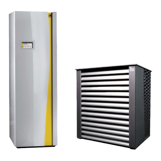
- Page 1 M O D E L : 4 0 0 V 2 3 0 V W I T H N AV I G AT O R 2 . 0 AIR HEAT PUMP WITH INVERTER-TECHNOLOGY iDM iPump A/T HEAT PUMPS FROM AUSTRIA www.idm-energie.at...
-
Page 2: Table Of Contents
3.4. Connections indoor unit 3.5. Dimensions Outdoor unit 3.6. Connections Outdoor unit 3.7. Technical data 3.8. Performance data according to EN 14511 3.9. Cooling data detailed iPump A 3-11 3.10. Filling quantity refrigerant 3.11. Maximum heigth difference 3.12. Limits of use 4. T RANSPORT 5. - Page 3 11. H YDRAULIC DIAGRAMS 11.1. iPump A 3-11 with direct heating circuit and hot water circulation 11.2. iPump A 3-11 with direct heating circuit, cooling, hot water circulation and one mixer heating circuit 12. H EATING SIDE INSTALLATION 13. D...
-
Page 4: General Information
1. 4 . I ns t al la t io n r o o m The internal unit of the iPump A 3-11 should be ins- Please read through this documentation carefully. talled in a frost-proof room. The Room temperature It contains important information for correct should be between 5°C and 25°C. -
Page 5: Sound Emission
1 . 5. S o un d em i ss ion 1. 1 0. S e r v ic i ng a nd mai nt e nanc e The iPump A 3-11 outdoor unit is very quiet in opera- Regular maintenance control and servicing of all tion thanks to the design. -
Page 6: Acoustic Evaluation
The sound power be calculated with the iDM-sound calculator. can only be determined via mathematical calculation The calculation of the sound pressure level shall be... - Page 7 Finally, the determined rating level can be compared with legal limit values (e.g. „TA Lärm“). (C) IDM ENERGIESYSTEME GMBH Installation instructions iPump A 3-11...
-
Page 8: Description
400 V or 230 V power supply. For monovalent heating and cooling of single- and The Indoor unit of the iPump A 3-11 includes the con- multiple dwellings with the heat source air. In this denser, a high effi ciency loading pump, the switching... -
Page 9: Dimensions Indoor Unit
5Inlet cables of sensors 6 LAN-Connection 7 Circulation connection 3/4“ 8 Cable inlet main current 9 Refrigerant pipe - liquid line 12 mm 10 Refrigerant pipe - hot gas line 16 mm Front view (C) IDM ENERGIESYSTEME GMBH Installation instructions iPump A 3-11... -
Page 10: Dimensions Outdoor Unit
3 .5. Di me n si on s Ou t d oor u n it Side view / left Front view Outlet side Inlet side 3 .6. Co n n ections O ut d oor un i t View from below Outlet side Inlet side (C) IDM ENERGIESYSTEME GMBH Installation instructions iPump A 3-11... -
Page 11: Technical Data
Sound power level maximum according to EN 12102 outdoor unit dB(A) Sound reduced night operation dB(A) The sound pressure level can be calculated with the iDM-sound calculation tool Dimensions indoor unit Height / Width / Depth 1950 / 600 / 786... - Page 12 12°C cold water temperature / 58°C buffer temperature 12°C cold water temperature / 75°C buffer temperature Oil elevation arcs must be installed according to regulation (see page 15)! at 80% pump capacity (C) IDM ENERGIESYSTEME GMBH Installation instructions iPump A 3-11...
-
Page 13: Performance Data According To En 14511
2,12 2,02 Heat output Power intake 4,26 3,89 3,55 3,34 3,10 2,71 2,20 1,98 Heat output Power intake Air-inlet temperature [°C] Heat output Power intake 3,55 3,18 2,80 2,62 2,39 2,12 (C) IDM ENERGIESYSTEME GMBH Installation instructions iPump A 3-11... -
Page 14: Cooling Data Detailed Ipump A
All 3 points must be fulfi lled independently. This is possible via the Navigator Pro. The entire distribution system has to fulfi ll the 3 mentioned points. To ensure a large cooling demand, the cooling limit has to be set as high as possible. (C) IDM ENERGIESYSTEME GMBH Installation instructions iPump A 3-11... - Page 15 Heat output at fl ow temperature 35°C NOMINAL Air-inlet temperature [°C] Heat output at fl ow temperature 45°C NOMINAL Air-inlet temperature [°C] (C) IDM ENERGIESYSTEME GMBH Installation instructions iPump A 3-11...
- Page 16 3. Description Description Heat output at fl ow temperature 55°C NOMINAL Air-inlet temperature [°C] Heat output at nominal speed Air-inlet temperature [°C] (C) IDM ENERGIESYSTEME GMBH Installation instructions iPump A 3-11...
-
Page 17: Filling Quantity Refrigerant
3 . 10. Fi ll in g q ua n t it y re f rig e ran t The iPump A 3-11 is pre-fi lled with refrigerant. Up to a distance of 6 m between indoor unit and outdoor unit no refrigerant no additional needs to be refi... -
Page 18: Limits Of Use
3 .12. Li mits of u se The heating of other fl uids as heating water is not permitted with the iPump A 3-11 (for heating water quality, see page 45). Heat pumps are by nature subjects to limits of use regarding of pressure and temperature (see diagram). -
Page 19: Transport
The device must be lifted and secured with a corresponding number of people. Sack barrow Transport over stairs for the iPump When transporting, the iPump A 3-11 may not be tilted more than 45 °. (C) IDM ENERGIESYSTEME GMBH Installation instructions iPump A 3-11... -
Page 20: Disassamble The Ipump
5. Disassamble the iPump 5. Disassamble the iPump disassemble the ipump The indoor unit of the iPump A 3-11 can be disassem- bled for the transport to the boiler room. To remove the front panel, the interlocking device must be opened with a screw driver or a pointed object. - Page 21 The electrical pan is secured by a safety rope against unintentional hinge down. Anyway, ensure that the electrical pan does not fall down when loosing the fi xing screws. Loos the fi xing screws Safety rope Locking nut (C) IDM ENERGIESYSTEME GMBH Installation instructions iPump A 3-11...
- Page 22 The insulation must be restored correctly after assembly. When opening the fi ttings, please ensure that no electrical cables are not beeing damaged. Armafl ex insulation (C) IDM ENERGIESYSTEME GMBH Installation instructions iPump A 3-11...
- Page 23 All described sensors above must be installed in the immersion sleeves. LAN connection Hot water sensor B48 Hot water sensor B41 bottom area Flow rate transmitter B2 Heat pump fl ow sensor Plug for switching valve (C) IDM ENERGIESYSTEME GMBH Installation instructions iPump A 3-11...
- Page 24 Also it is recommended to use safety shoes with corresponding protective caps. Refrigeration equipment Hot water tank After the iPump has been brought into the boiler room, the assembly takes place in reverse order. Timber beams (C) IDM ENERGIESYSTEME GMBH Installation instructions iPump A 3-11...
-
Page 25: Connecting The Control Unit
(C) IDM ENERGIESYSTEME GMBH Installation instructions iPump A 3-11... -
Page 26: Assembly And Hydraulic Installation
View from above 6 .1. A sse mb ly of t h e in d oor u n it The iPump A 3-11 must be installed in a frost- protected room by an approved specialist. The room temperature must be between 5°C and 25°C. -
Page 27: Assembly Of The Outdoor Unit
Suction side Condensate run-off In this variant, the outdoor unit of the iPump A 3-11 is mounted on two bases. The refrigerant lines and the condenser run-off are routed between the two bases and must be connected to the outdoor unit. The load capacity of the base must be given. -
Page 28: Place Of Installation
This could be 6 liters per defrost cycle within 2 minutes. The condensate run-off must be frost-proof. To avoid damages caused by animals, such as rodents or insects, all cable- and pipe openings have to be closed. (C) IDM ENERGIESYSTEME GMBH Installation instructions iPump A 3-11... -
Page 29: Assembling Of The Outdoor Unit On The Concrete Base
For this see the scope of earthed. After maintenance work, make sure that the delivery for iPump A 3-11 on page 8. equipotential bonding is properly restored. For the outdoor unit, a 10 mm hole is provided for connecting the equipotential bonding or lightning protection. -
Page 30: Condensation Run-Off
The heating band (2 m) will be placed in the drain hose. The condensation bin and the run- off have to be checked for soiling regularly . The minimum distances must be maintained due to perform maintenance. (C) IDM ENERGIESYSTEME GMBH Installation instructions iPump A 3-11... - Page 31 No tes: (C) IDM ENERGIESYSTEME GMBH Installation instructions iPump A 3-11...
-
Page 32: Connection Of The Refrigerant Circuit
Liquid line 12 mm Hot gas line 16 mm On the refrigerant side the indoor unit and the outdoor unit of the iPump A 3-11 are „hermetically tight“. Open refrigerant pipes must be protected against moisture and dirth with caps or tapes. -
Page 33: Connection Of The Indoor Unit On Refrigerant Side
Energiesysteme GmbH. The connections for the refrigerant pipes are optional on the right or left side of the iPump A 3-11 indoor unit. To connect the refrigerant pipes, the protecting caps must be cut. -
Page 34: Wall Opening
Only tools recommended for use in refrigeration may be used. (For example: bending wrench, pipe cutter, deburrer and fl anging tool). Refrigerant pipes may not be sawn. It must be ensured during all work that dirt, shavings, water, etc. do not enter the refrigerant pipes. (C) IDM ENERGIESYSTEME GMBH Installation instructions iPump A 3-11... -
Page 35: Electrical Power Supply
8. 3 . E le c t r i ca l c o nne c t i o n i ndo o r u nit The electrical connection must be made by a qualifi ed For the iPump A 3-11, separate cable entries for the person and must be registered with the local electri- main power supply and for the sensors have been city company. -
Page 36: Electrical Connection Of The Outdoor Unit
If the iPump should be connected to my- iDM (Network), the network cable must be provided on site. Electrical connection box for the ventilator The wiring may only be done by a qualifi... -
Page 37: Connection Diagram Of The Electrical Module
113 114 115 116 117 118 119 120 121 122 123 Analog inputs Mains Impuls counter 230V/50Hz Digital input SD - Card RS232 X36 132 131 130 - SH EEV2 X4 EEV1 X2 LAN X33 (C) IDM ENERGIESYSTEME GMBH Installation instructions iPump A 3-11... -
Page 38: Connection Of The Central Unit
Sensor design NAVIGATOR Pro additional board The sensor positions are shown in the relevant To use the iDM single-room control, an additional installation diagram. Reliable functioning can only board must be connected to the touch display of NA- be ensured by correct positioning and a good heat VIGATOR 2.0. -
Page 39: Commissioning
- The heat pump may only be commissioned by a 9. 3 . Fau lt s customer service engineer specially trained by iDM The iPump A 3-11 is fi tted with various safety devices Energiesysteme GmbH. to ensure that no damage can be caused to the - The heating and any storage tank must be fi... -
Page 40: Magnesium Protection Anode
The magnesium protection anode which is integrated Anode testing in the buffer of the iPump A 3-11 must be checked An instruction to testing the anode can be seen under acc. to DIN 4753-3 for the fi rst time after two years... -
Page 41: Exchange Of The Magnesium Protection Anode
The new anode will be screwed fi rmly and the black connection cable between the anode and the buffer must be pluged. After refi lling the buffer, it must be checked for leaks in the area of the protective anode. (C) IDM ENERGIESYSTEME GMBH Installation instructions iPump A 3-11... - Page 42 10. Magnesium protection anode magnesium protection anode No tes: (C) IDM ENERGIESYSTEME GMBH Installation instructions iPump A 3-11...
-
Page 43: Hydraulic Diagrams
1 1 .1. i Pump A 3 - 11 w it h dire c t h e at ing cir c u i t and ho t w at e r c i r c u l at i o n The iPump A 3-11 is a heat pump with inverter technology for continous power control. Therefore it is possible to provide direct heating circuits. -
Page 44: Ipump A 3-11 With Direct Heating Circuit, Cooling, Hot Water Circulation And One Mixer Heating Circuit
The iPump A 3-11 is a heat pump with inverter technology for continous power control. Therefore it is possible to provide direct heating circuits. An overfl ow valve must be installed in the direct heating circuit to guarantee a minimum fl... -
Page 45: Heating Side Installation
In case of repairs avoided. If it is necessary to empty the storage vessel of the iPump A 3-11 due to repair work, the system must be refi lled with treated water. Heating water quality Depending on the quality of the heating water, lime... -
Page 46: Declaration Of Confirmity, Product Fiche
13. Declaration of confirmity, product fiche 13. Declaration of confirmity, product fiche declaration of confirmity, product fiche (C) IDM ENERGIESYSTEME GMBH Installation instructions iPump A 3-11... - Page 47 IDM-Energiesysteme GmbH A-9971 Matrei i.O., Seblas 16 – 18, Telefon +43 (0)4875 6172-0 Firmenbuch.Nr. 44919h, LG Innsbruck, Firmensitz: 9971 Matrei i.O., UID-Nr.: ATU 433 604 02 (C) IDM ENERGIESYSTEME GMBH Installation instructions iPump A 3-11...
- Page 48 PRACTICAL KNOWLEDGE FOR SALES AND TECHNOLOGY The comprehensive range of seminars for sp ecialists at the IDM POWER FA MILY is available to you any time on our website. We look for ward to re ceiving your re gist ration.
Need help?
Do you have a question about the iPump A 3-11 and is the answer not in the manual?
Questions and answers