
Related Manuals for Flexim FLUXUS F808 A1 Series


Summary of Contents for Flexim FLUXUS F808 A1 Series
- Page 1 User Manual UMFLUXUS_F808_809V1-2-1EN Ultrasonic flowmeter for liquids in explosive atmospheres FLUXUS F808**-A1 FLUXUS F808**-F1 FLUXUS F808**-F2 FLUXUS F809**-A1 FLUXUS F809**-F1...
- Page 2 FLUXUS is a registered trademark of FLEXIM GmbH. FLEXIM GmbH Boxberger Straße 4 12681 Berlin Germany Phone: +49 (30) 936 67 660 Fax: +49 (30) 936 67 680 E-mail: info@flexim.de www.flexim.com User manual for FLUXUS F808, F809 UMFLUXUS_F808_8091V1-2-1EN, 2019-08-23 Copyright (©) FLEXIM GmbH 2019...
- Page 3 FLUXUS F808, F809 Die Sprache, in der die Anzeigen auf dem Messumformer erscheinen, kann eingestellt werden (siehe Abschnitt 9.6). The transmitter can be operated in the language of your choice (see section 9.6). Il est possible de sélectionner la langue utilisée par le transmetteur à l'écran (voir section 9.6). El caudalímetro puede ser manejado en el idioma de su elección (ver sección 9.6).
- Page 4 FLUXUS F808, F809 UMFLUXUS_F808_8091V1-2EN, 2016-09-26...
-
Page 5: Table Of Contents
Table of Contents FLUXUS F808, F809 Table of Contents Introduction ................9 Regarding this user manual. - Page 6 FLUXUS F808, F809 Table of Contents Installation of the transducers ............77 Pipe preparation .
- Page 7 Table of Contents FLUXUS F808, F809 Libraries ................132 14.1 Partitioning of the coefficient memory .
- Page 8 FLUXUS F808, F809 Table of Contents UMFLUXUS_F808_8091V1-2-1EN, 2019-08-23...
-
Page 9: Introduction
• unsuitable or insufficient maintenance • repair of FLUXUS by unauthorized personnel FLEXIM assumes no responsibility for injury to the customer or third persons proximately caused by the material owing to defects in the product which were not predictable or for any indirect damages. -
Page 10: Handling
FLUXUS F808, F809 2 Handling Handling First inspection The measuring instrument has already been tested thoroughly at factory. At delivery, proceed to a visual control to make sure that no damage has occurred during transportation. Check that the specifications of the measuring instrument delivered correspond to the specifications given on the pur- chase order. -
Page 11: General Principles
3 General principles FLUXUS F808, F809 General principles For the ultrasonic measurement of the flow rate, the flow velocity of the fluid flowing in a pipe is determined. Further phys- ical quantities (e.g., volumetric flow rate, mass flow rate) are derived from the flow velocity and from additional physical quantities, if necessary. - Page 12 FLUXUS F808, F809 3 General principles Sound speed c Speed of the propagating sound. The sound speed depends on the mechanical properties of the fluid or the pipe material. In pipe materials and other solid materials, a distinction is made between the longitudinal and transversal sound speed. For the sound speed of some fluids and materials see annex C.1.
- Page 13 3 General principles FLUXUS F808, F809 transducer (emitter) transducer (receiver) reduction in distance in the transducer α α α pipe wall β β γ flow direction γ of the fluid sound path without flow sound path with flow Fig. 3.2: Sound path of the signal in the flow direction transducer (receiver) transducer (emitter) increase in distance...
- Page 14 FLUXUS F808, F809 3 General principles 3.2.3 Measurement of the flow velocity in the NoiseTrek mode When fluids with a high proportion of gas bubbles or solid particles are measured, the attenuation of the ultrasonic signal increases and can inhibit the propagation of the signal in the fluid. A measurement in the TransitTime mode is no longer possible.
-
Page 15: Measurement Arrangements
3 General principles FLUXUS F808, F809 NoiseTrek parallel beam For small pipes or highly damping fluids, the transit time of measuring signals can be very small due to scattering bodies and bubbles. This leads to a deterioration of the signal quality. The NoiseTrek parallel beam mode works the same way the NoiseTrek mode does, the only difference is that the sending and receiving process do not occur in the same transducer. - Page 16 FLUXUS F808, F809 3 General principles Beam The path covered by the ultrasonic signal between the transducers: the transducer emitting the ultrasonic signal and the transducer receiving it. A beam consists of 1 or several sound paths (see Fig. 3.9 or Fig. 3.10). Fig.
- Page 17 3 General principles FLUXUS F808, F809 3.3.2 Examples diagonal arrangement with 1 beam reflection arrangement with 1 beam 1 transducer pair 1 transducer pair 1 sound path 2 sound paths 1 beam 1 beam 1 plane 1 plane diagonal arrangement with 2 beams reflection arrangement with 2 beams and 2 planes 2 transducer pairs 2 transducer pairs...
-
Page 18: Description Of The Transmitter
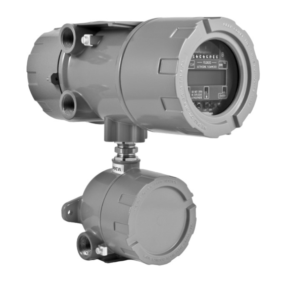
FLUXUS F808, F809 4 Description of the transmitter Description of the transmitter FLUXUS F808 The transmitter consists of 1 housing (see Fig. 4.1). The command panel is on the front side of the housing. The keys are operated by a magnetic pen with closed housing. The terminals for the connection of transducers, outputs and power supply are on the back side of the housing. -
Page 19: Keyboard
4 Description of the transmitter FLUXUS F808, F809 Keyboard The keyboard consists of 5 keys. Tab. 4.1: General functions ENTER confirmation of selection or input BRK + CLR + ENTER RESET: Press these 3 keys simultaneously to correct a malfunction. The reset has the same effect as restarting the transmitter. -
Page 20: Selection Of The Measuring Point
FLUXUS F808, F809 5 Selection of the measuring point Selection of the measuring point Attention! Observe the "Safety instructions for the use in explosive atmospheres" (see document SIFLUXUS, SIFLUXUS_808_FM,SIFLUXUS_808_F2 and SIFLUXUS_1N62). The correct selection of the measuring point is crucial for achieving reliable measurement results and a high measurement accuracy. - Page 21 5 Selection of the measuring point FLUXUS F808, F809 Observe the notes in the following table: Tab. 5.1: Recommended transducer position horizontal pipe Select a measuring point where the transducers can be mounted on the side of the pipe, allowing the sound waves to propagate in the pipe horizontally.
-
Page 22: Undisturbed Flow Profile
FLUXUS F808, F809 5 Selection of the measuring point Undisturbed flow profile Some flow elements (e. g., elbows, slide valves, valves, control valves, pumps, reducers, diffusers, etc.) distort the flow profile in their vicinity. The axisymmetrical flow profile needed for correct measurement is no longer given. A careful selec- tion of the measuring point helps to reduce the impact of disturbance sources. - Page 23 5 Selection of the measuring point FLUXUS F808, F809 Tab. 5.2: Recommended distance from disturbance sources; D - nominal pipe diameter at the measuring point, l - recommended distance between disturbance source and transducer position disturbance source: reducer supply line: l ≥ 10 D return line: l ≥...
-
Page 24: Selection Of The Measurement Arrangement Taking Into Account The Measuring Range And The Measuring Conditions
FLUXUS F808, F809 5 Selection of the measuring point Selection of the measurement arrangement taking into account the measuring range and the measuring conditions Diagonal arrangement with 1 beam Reflection arrangement with 1 beam • wider flow velocity and sound speed range compared to •... - Page 25 5 Selection of the measuring point FLUXUS F808, F809 Selection of the sound beam plane near an elbow Vertical pipes Horizontal pipes flow direction elbow plane elbow plane flow direction • The sound beam plane (see section 3.3.1) has an angle •...
-
Page 26: Installation Of Fluxus F808
FLUXUS F808, F809 6 Installation of FLUXUS F808 Installation of FLUXUS F808 Attention! Observe the "Safety instructions for the use in explosive atmospheres" (see document SIFLUXUS, SIFLUXUS_808_FM,SIFLUXUS_808_F2 and SIFLUXUS_1N62). Location • Select the measuring point according to the recommendations in chapter 3 and 5. •... - Page 27 6 Installation of FLUXUS F808 FLUXUS F808, F809 6.3.2 Pipe installation Installation on a 2" pipe The instrument mounting plate (2) is fixed to the pipe using a shackle (1) (see Fig. 6.3). • Fix the transmitter to the instrument mounting plate. •...
-
Page 28: Connection Of The Transmitter
FLUXUS F808, F809 6 Installation of FLUXUS F808 Connection of the transmitter Attention! Observe the Safety Instructions for the Use in Explosive Atmosphere (see document SIFLUXUS, SIFLUXUS_808_FM,SIFLUXUS_808_F2 and SIFLUXUS_1N62). Attention! The degree of protection of the transmitter will only be ensured if the cable glands are firmly tightened and the housing covers are tightly screwed to the housing. -
Page 29: Connection Of The Transducers To The Transmitter F808**-A1
6 Installation of FLUXUS F808 FLUXUS F808, F809 6Installation of FLUXUS F808 Connection of the transducers to the transmitter F808**-A1 Note! If transducers are replaced or added, the sensor module also has be replaced or added (see section 6.11). It is recommended to run the cables from the measuring point to the transmitter before connecting the transducers to avoid load on the connectors. - Page 30 FLUXUS F808, F809 6 Installation of FLUXUS F808 6.5.1.2 Transducer cable with plastic cable jacket and stripped cable ends Attention! Observe the "Safety instructions for the use in explosive atmospheres" (see document SIFLUXUS). • The transmitter has 1 cable gland for the connection of the transducers. •...
- Page 31 6 Installation of FLUXUS F808 FLUXUS F808, F809 6.5.2 Connection of the extension cable to the transmitter Attention! Observe the "Safety instructions for the use in explosive atmospheres" (see document SIFLUXUS). • The transmitter has 1 cable gland for the connection of the transducers. •...
- Page 32 FLUXUS F808, F809 6 Installation of FLUXUS F808 6.5.3 Connection of the transducer cable to the junction box 6.5.3.1 Transducer cable with plastic cable jacket and stripped cable ends Attention! Observe the "Safety instructions for the use in explosive atmospheres" (see document SIFLUXUS). •...
- Page 33 6 Installation of FLUXUS F808 FLUXUS F808, F809 6.5.3.2 Transducer cable with stainless steel conduit and stripped cable ends Attention! Observe the "Safety instructions for the use in explosive atmospheres" (see document SIFLUXUS). • Remove the right blind plug for the connection of the transducer cable (see Fig. 6.10). •...
- Page 34 FLUXUS F808, F809 6 Installation of FLUXUS F808 6.5.4 Connection of the extension cable to the junction box 6.5.4.1 Without potential separation (standard) The connection of an extension cables to a junction box without potential separation ensures that transducer, junction box and transmitter are on the same potential.
- Page 35 6 Installation of FLUXUS F808 FLUXUS F808, F809 Tab. 6.6: Terminal assignment (junction box, KL2) terminal connection (extension cable) white or marked cable (core) white or marked cable (internal shield) brown cable (internal shield) brown cable (core) cable gland external shield 6.5.4.2 Connection with potential separation If earthing on the same potential cannot be ensured e.g., in measurement arrangements with long extension cables, ex-...
- Page 36 FLUXUS F808, F809 6 Installation of FLUXUS F808 K L 2 K L 1 shield terminal extension cable transducer cable external shield extension cable compression part basic part cap nut cable gland Fig. 6.12: Connection of the extension cable to the junction box Tab.
-
Page 37: Connection Of The Transducers To The Transmitter F808**-F1
6 Installation of FLUXUS F808 FLUXUS F808, F809 6Installation of FLUXUS F808 Connection of the transducers to the transmitter F808**-F1 Note! If transducers are replaced or added, the sensor module also has to be replaced or added (see section 6.11). It is recommended to run the cables from the measuring point to the transmitter before connecting the transducers to avoid load on the connectors. - Page 38 FLUXUS F808, F809 6 Installation of FLUXUS F808 external shield 70 mm transducers 20 mm 10 mm extension cable equipotential bonding terminal (transducers) Fig. 6.14: Connection of the extension cable Tab. 6.9: Terminal assignment (transmitter, KL 4) terminal connection (extension cable) white or marked cable (core) white or marked cable (internal shield) brown cable (internal shield)
- Page 39 6 Installation of FLUXUS F808 FLUXUS F808, F809 Tab. 6.11: Terminal assignment (terminal board KFM1) terminal connection (extension cable) terminal strip KL3 signal internal shield external shield internal shield signal UMFLUXUS_F808_8091V1-2-1EN, 2019-08-23...
-
Page 40: Connection Of The Transducers To The Transmitter F808**-F2
FLUXUS F808, F809 6 Installation of FLUXUS F808 6Installation of FLUXUS F808 Connection of the transducers to the transmitter F808**-F2 Note! If transducers are replaced or added, the sensor module also has to be replaced or added (see section 6.11). It is recommended to run the cables from the measuring point to the transmitter before connecting the transducers to avoid load on the connectors. - Page 41 6 Installation of FLUXUS F808 FLUXUS F808, F809 6.7.1.2 Transducer cable with SMB connectors Attention! Observe the "Safety instructions for the use in explosive atmospheres" (see document SIFLUXUS_808_F2). For the installation of transducers with SMB connectors a SMB adapter is required. •...
- Page 42 FLUXUS F808, F809 6 Installation of FLUXUS F808 6.7.2 Connection of the extension cable to the transmitter Attention! Observe the "Safety instructions for the use in explosive atmospheres" (see document SIFLUXUS_808_F2). • The transmitter has 1 cable gland for the connection of the transducers. •...
- Page 43 6 Installation of FLUXUS F808 FLUXUS F808, F809 6.7.3 Connection of the transducer cable to the junction box 6.7.3.1 Transducer cable with SMB connectors Attention! Observe the "Safety instructions for the use in explosive atmospheres" (see document SIFLUXUS_808_F2). The transducer cable with SMB connectors and the extension cable are connected via the junction box JB04. •...
- Page 44 FLUXUS F808, F809 6 Installation of FLUXUS F808 6.7.4 Connection of the extension cable to the junction box 6.7.4.1 Connection without potential separation (standard) The connection of an extension cables to a junction box without potential separation ensures that transducer, junction box and transmitter are on the same potential.
- Page 45 6 Installation of FLUXUS F808 FLUXUS F808, F809 Tab. 6.16: Terminal assignment (junction box JB04, KL2) terminal connection (extension cable) white or marked cable (core) white or marked cable (internal shield) brown cable (internal shield) brown cable (core) cable gland external shield 6.7.4.2 Connection with potential separation...
- Page 46 FLUXUS F808, F809 6 Installation of FLUXUS F808 K L 2 shield terminal extension cable transducer cable external shield extension cable compression part basic part cap nut cable gland Fig. 6.21: Connection of the extension cable to the junction box Tab.
-
Page 47: Power Supply
6 Installation of FLUXUS F808 FLUXUS F808, F809 6Installation of FLUXUS F808 Power supply Attention! According to IEC 61010-1:2010, a switch has to be provided near the measuring instrument in the building installation, easily accessible for the user and marked as a disconnection device for the mea- suring instrument. - Page 48 FLUXUS F808, F809 6 Installation of FLUXUS F808 Tab. 6.18: Connection of the power supply (KL2) terminal connection terminal connection phase neutral earth earth 6.8.2 FLUXUS F808**-F1 Attention! Observe the "Safety instructions for the use in explosive atmospheres" (see document SIFLUXUS_808_FM and SIFLUXUS_1N62).
-
Page 49: Outputs
6 Installation of FLUXUS F808 FLUXUS F808, F809 6Installation of FLUXUS F808 Outputs Attention! Observe the "Safety instructions for the use in explosive atmospheres" (see document SIFLUXUS, SIFLUXUS_808_FM,SIFLUXUS_808_F2 and SIFLUXUS_1N62). Attention! The outputs may only be connected to a low voltage circuit (max. 30 V AC or 42 V DC against earth). For the connection of the output cable to the transmitter, see box "Cable connection", p. - Page 50 FLUXUS F808, F809 6 Installation of FLUXUS F808 Tab. 6.20: Circuits of the outputs output transmitter remark internal circuit connection external circuit active current current loop < 500 Ω loop/HART = 24 V F808**-A1 I1: 2 (+) F808**-F1 I1: 1 (-) HART mode ƒ...
- Page 51 6 Installation of FLUXUS F808 FLUXUS F808, F809 Tab. 6.20: Circuits of the outputs output transmitter remark internal circuit connection external circuit binary output = 8.2 V (open collector) B1: 6 (+) = 1 kΩ NAMUR DIN EN 60947-5-6 (NAMUR) B1: 5 (-) RS485 120 Ω...
-
Page 52: Serial Interface
FLUXUS F808, F809 6 Installation of FLUXUS F808 6Installation of FLUXUS F808 6.10 Serial interface Attention! Observe the "Safety instructions for the use in explosive atmospheres" (see document SIFLUXUS, SIFLUXUS_808_FM,SIFLUXUS_808_F2 and SIFLUXUS_1N62). 6.10.1 RS232 interface The RS232 interface can only be connected outside of an explosive atmosphere because the housing has to be opened (see Fig. -
Page 53: Sensor Module (Sensprom)
6 Installation of FLUXUS F808 FLUXUS F808, F809 6Installation of FLUXUS F808 6.11 Sensor module (SENSPROM) Attention! Observe the "Safety instructions for the use in explosive atmospheres" (see document SIFLUXUS, SIFLUXUS_808_FM,SIFLUXUS_808_F2 and SIFLUXUS_1N62). The sensor module contains important transducer data for the operation of the transmitter with the transducers. It is con-- nected to the connector strips above the display of the transmitter. -
Page 54: Installation Of Fluxus F809
FLUXUS F808, F809 7 Installation of FLUXUS F809 Installation of FLUXUS F809 Attention! Observe the "Safety instructions for the use in explosive atmospheres" (see document SIFLUXUS, SIFLUXUS_808_FM and SIFLUXUS_1N62). Location • Select the measuring point according to the recommendations in chapter 3 and 5. •... -
Page 55: Installation
7 Installation of FLUXUS F809 FLUXUS F808, F809 Installation 7.3.1 Wall installation • Fix the housing to the instrument mounting plate (2) (see Fig. 7.2). • Fix the transmitter to the wall. Fig. 7.2: Wall installation UMFLUXUS_F808_8091V1-2-1EN, 2019-08-23... - Page 56 FLUXUS F808, F809 7 Installation of FLUXUS F809 7.3.2 Pipe Installation Installation on a 2" pipe The instrument mounting plate (2) is fixed to the pipe using a shackle (1) (see Fig. 7.3). • Fix the transmitter to the instrument mounting plate. •...
-
Page 57: Connection Of The Transmitter
7 Installation of FLUXUS F809 FLUXUS F808, F809 Connection of the transmitter Attention! Observe the "Safety instructions for the use in explosive atmospheres" (see document SIFLUXUS, SIFLUXUS_808_FM and SIFLUXUS_1N62). Attention! The degree of protection of the transmitter will only be ensured if the cable glands are firmly tightened and the housing covers are tightly screwed to the housing. -
Page 58: Connection Of The Transducers To The Transmitter F809**-A1
FLUXUS F808, F809 7 Installation of FLUXUS F809 7Installation of FLUXUS F809 Connection of the transducers to the transmitter F809**-A1 Note! If transducers are replaced or added, the sensor module also has to be replaced or added (see section 7.10). It is recommended to run the cables from the measuring point to the transmitter before connecting the transducers to avoid load on the connectors. - Page 59 7 Installation of FLUXUS F809 FLUXUS F808, F809 7.5.1.2 Transducer cable with plastic cable jacket and stripped cable ends Attention! Observe the "Safety instructions for the use in explosive atmospheres" (see document SIFLUXUS). • The transmitter has 2 cable glands for the connection of the transducers. •...
- Page 60 FLUXUS F808, F809 7 Installation of FLUXUS F809 7.5.2 Connection of the extension cable to the transmitter Attention! Observe the "Safety instructions for the use in explosive atmospheres" (see document SIFLUXUS). • The transmitter has 2 cable glands for the connection of the transducers. •...
- Page 61 7 Installation of FLUXUS F809 FLUXUS F808, F809 7.5.3 Connection of the transducer cable to the junction box 7.5.3.1 Transducer cable with plastic cable jacket and stripped cable ends Attention! Observe the "Safety instructions for the use in explosive atmospheres" (see document SIFLUXUS). •...
- Page 62 FLUXUS F808, F809 7 Installation of FLUXUS F809 7.5.3.2 Transducer cable with stainless steel conduit and stripped cable ends Attention! Observe the "Safety instructions for the use in explosive atmospheres" (see document SIFLUXUS). • Remove the right blind plug for the connection of the transducer cable (see Fig. 7.10). •...
- Page 63 7 Installation of FLUXUS F809 FLUXUS F808, F809 7.5.4 Connection of the extension cable to the junction box 7.5.4.1 Connection without potential separation (standard) The connection of the extension cable to a junction box without potential separation ensures that transducer, junction box and transmitter are on the same potential.
- Page 64 FLUXUS F808, F809 7 Installation of FLUXUS F809 Tab. 7.6: Terminal assignment (junction box, KL2) terminal connection (extension cable) white or marked cable (core) white or marked cable (internal shield) brown cable (internal shield) brown cable (core) cable gland external shield 7.5.4.2 Connection with potential separation If earthing on the same potential cannot be ensured e.g., in measurement arrangements with long extension cables, ex-...
- Page 65 7 Installation of FLUXUS F809 FLUXUS F808, F809 K L 2 K L 1 shield terminal extension cable transducer cable external shield extension cable compression part basic part cap nut cable gland Fig. 7.12: Connection of the extension cable to the junction box Tab.
-
Page 66: Connection Of The Transducers To The Transmitter F809**-F1
FLUXUS F808, F809 7 Installation of FLUXUS F809 7Installation of FLUXUS F809 Connection of the transducers to the transmitter F809**-F1 Note! If transducers are replaced or added, the sensor module also has to be replaced or added (see section 7.10). It is recommended to run the cables from the measuring point to the transmitter before connecting the transducers to avoid load on the connectors. - Page 67 7 Installation of FLUXUS F809 FLUXUS F808, F809 external shield 70 mm equipotential bonding terminal equipotential bonding terminal (transducers) (transducers) 20 mm 10 mm transducers transducers extension cable Fig. 7.14: Connection of the extension cable Tab. 7.9: Terminal assignment (transmitter) terminal connection (extension cable) white or marked cable (core)
- Page 68 FLUXUS F808, F809 7 Installation of FLUXUS F809 Tab. 7.11: Terminal assignment (terminal board KFM1, KL3) terminal connection (extension cable) signal internal shield external shield internal shield signal UMFLUXUS_F808_8091V1-2-1EN, 2019-08-23...
-
Page 69: Power Supply
7 Installation of FLUXUS F809 FLUXUS F808, F809 7Installation of FLUXUS F809 Power supply Attention! According to IEC 61010-1:2010, a switch must be provided near the measuring instrument, easily ac- cessible and marked as a disconnection device for the measuring instrument. If the measuring instrument is used in an explosive atmosphere, the switch should be installed out- side the explosive atmosphere. - Page 70 FLUXUS F808, F809 7 Installation of FLUXUS F809 Tab. 7.12: Connection of the power supply AC (F809**-A1) terminal connection terminal connection phase neutral earth earth 7.7.2 FLUXUS F809**-F1 Attention! Observe the "Safety instructions for the use in explosive atmospheres" (see document SIFLUXUS_808_FM and SIFLUXUS_1N62).
-
Page 71: Outputs
7 Installation of FLUXUS F809 FLUXUS F808, F809 7Installation of FLUXUS F809 Outputs Attention! Observe the "Safety instructions for the use in explosive atmospheres" (see document SIFLUXUS, SIFLUXUS_808_FM and SIFLUXUS_1N62). Attention! The outputs may only be connected to a low voltage circuit (max. 30 V AC or 42 V DC against earth). For the connection of the output cable to the transmitter, see box "Cable connection", p. - Page 72 FLUXUS F808, F809 7 Installation of FLUXUS F809 Tab. 7.14: Circuits of the outputs output transmitter external circuit remark internal circuit connection active current loop/HART current loop F809**-A1 < 500 Ω F809**-F1 I1/I2: 2/4 (+) I1/I2: 1/3 (-) HART mode = 24 V ƒ...
- Page 73 7 Installation of FLUXUS F809 FLUXUS F808, F809 Tab. 7.14: Circuits of the outputs output transmitter external circuit remark internal circuit connection frequency output = 5...30 V (open collector) F1: 2 (+) [kΩ] = U [mA] F809**-A1 = 2...100 mA F809**-F1 ≤...
- Page 74 FLUXUS F808, F809 7 Installation of FLUXUS F809 Tab. 7.14: Circuits of the outputs output transmitter external circuit remark internal circuit connection RS485 120 Ω termination resistor F809**-A1 F809**-F1 shield S The number, type and connections of the outputs are customized. is the sum of all ohmic resistances in the circuit (e.g.
-
Page 75: Serial Interface
7 Installation of FLUXUS F809 FLUXUS F808, F809 7Installation of FLUXUS F809 Serial interface Attention! Observe the "Safety instructions for the use in explosive atmospheres" (see document SIFLUXUS, SIFLUXUS_808_FM and SIFLUXUS_1N62). 7.9.1 RS232 interface The RS232 interface can only be connected outside of an explosive atmosphere because the housing has to be opened (see Fig. -
Page 76: Sensor Module (Sensprom)
FLUXUS F808, F809 7 Installation of FLUXUS F809 7Installation of FLUXUS F809 7.10 Sensor module (SENSPROM) Attention! Observe the "Safety instructions for the use in explosive atmospheres" (see document SIFLUXUS, SIFLUXUS_808_FM and SIFLUXUS_1N62). The sensor module contains important transducer data for the operation of the transmitter with the transducers. It is con-- nected to the connector strips above the display of the transmitter. -
Page 77: Installation Of The Transducers
8 Installation of the transducers FLUXUS F808, F809 Installation of the transducers Attention! Observe the Safety Instructions for the Use in Explosive Atmosphere (see document SIFLUXUS, SIFLUXUS_808_FM,SIFLUXUS_808_F2 and SIFLUXUS_1N62). Pipe preparation • The pipe has to be stable. It has to be able to withstand the pressure exerted by the transducer mounting fixture. Rust, paint or deposits on the pipe absorb the sound signal. -
Page 78: Transducer Mounting Fixture Variofix L (Permarail)
FLUXUS F808, F809 8 Installation of the Transducers 8Installation of the Transduc ers Transducer mounting fixture Variofix L (PermaRail) When measuring in reflection arrangement, the transducer mounting fixtures are mounted on the same side of the pipe (see Fig. 8.2). When measuring in diagonal arrangement, the transducer mounting fixtures are mounted on the opposite sides of the pipe (see Fig. - Page 79 8 Installation of the Transducers FLUXUS F808, F809 Tab. 8.1: Approximate values for the mounting of a Variofix L transducer frequency length of the rail length of the transducer (third character of the technical type) [mm] [mm] < 69 M, P <...
- Page 80 FLUXUS F808, F809 8 Installation of the Transducers Ratchet clasp • Cut the tension strap to length (pipe circumference + at least 120 mm). Attention! The edge of the tension strap is very sharp, leading to risk of injury. Debur sharp edges. •...
- Page 81 8 Installation of the Transducers FLUXUS F808, F809 metal spring tension strap clamp Fig. 8.10: Tension strap with tension strap clamp Fig. 8.11: Tension strap with metal spring screw of the clasp screw of the clasp Fig. 8.12: Band clamp clasp with tension strap Fig.
- Page 82 FLUXUS F808, F809 8 Installation of the Transducers 8.3.4 Fixing the rail to the pipe • Place one tension strap clamp in the rail (see tension strap clamp 1 in Fig. 8.16). Observe the orientation of the tension strap clamp. •...
- Page 83 8 Installation of the Transducers FLUXUS F808, F809 Quick release clasp • Insert the tension strap into tension strap clamp 1 and the metal spring (see Fig. 8.20 and Fig. 8.18). • Place the tension strap around the pipe and insert it into the clasp. •...
- Page 84 FLUXUS F808, F809 8 Installation of the Transducers • Repeat the steps to fix the second rail (see Fig. 8.23). Fig. 8.23: Pipe with 2 rails 8.3.5 Installation of the transducers in Variofix L • Press the transducers firmly into the transducer clamping fixtures of the covers until the transducers are tightly fixed (one transducer in each cover).
- Page 85 8 Installation of the Transducers FLUXUS F808, F809 • Put the covers with the transducers on the rail. • Correct the transducer distance, if necessary (see section 10.6.1 and 10.6.2). Note! Make sure that the coupling foil remains on the contact surface of the transducers. •...
-
Page 86: Transducer Mounting Fixture Variofix C
FLUXUS F808, F809 8 Installation of the Transducers 8Installation of the Transduc ers Transducer mounting fixture Variofix C When measuring in reflection arrangement, 1 transducer mounting fixture is mounted on the side of the pipe (see Fig. 8.27). When measuring in diagonal arrangement, 2 transducer mounting fixtures are mounted on the opposite sides of the pipe (see Fig. - Page 87 8 Installation of the Transducers FLUXUS F808, F809 8.4.1 Disassembly of Variofix C • Disassemble the transducer mounting fixture Variofix C. In order to remove the cover from the rail, bend the outer sides of the cover outwards (see Fig. 8.30). In order to remove the spring clip from the rail, slide it over the indentation on the rail and lift it off (see Fig.
- Page 88 FLUXUS F808, F809 8 Installation of the Transducers • Place the tension strap around the pipe (see Fig. 8.34). tension strap clamp Fig. 8.32: Tension strap with tension strap clamp tension strap clamp metal spring metal spring Fig. 8.33: Tension strap with metal spring and tension strap clamp •...
- Page 89 8 Installation of the Transducers FLUXUS F808, F809 screws Fig. 8.35: Rail on the pipe Installation of the rail with ratchet clasp • Cut the tension strap to length (pipe circumference + at least 120 mm). Note! The edge of the tension strap is very sharp, leading to risk of injury. Debur sharp edges. •...
- Page 90 FLUXUS F808, F809 8 Installation of the Transducers • Repeat the steps for the second tension strap. metal spring ratchet clasp tension strap clamp Fig. 8.38: Tension strap with metal spring, the ratchet clasp and tension strap clamp on the pipe lever screw of the clasp sense of rotation...
- Page 91 8 Installation of the Transducers FLUXUS F808, F809 8.4.3 Installation of the transducers in Variofix C • Put coupling foil (or some coupling compound for a short-term installation) on the contact surface of the transducers. The coupling foil can be fixed to the contact surface with a small amount of coupling compound. Note! If coupling foil is used: If the signal is not sufficient for the measurement, use coupling compound in- stead of coupling foil.
- Page 92 FLUXUS F808, F809 8 Installation of the Transducers The cover can be removed from the mounted transducer mounting Variofix C fixture as follows: • Use a lever tool to remove the cover. • Insert the lever tool in one of the 4 openings of the cover (see Fig. 8.44). •...
-
Page 93: Transducer Mounting Fixture Permafix
8 Installation of the Transducers FLUXUS F808, F809 8Installation of the Transducers Transducer mounting fixture PermaFiX Attention! Observe the "Safety and installation instructions for the use in hazardous (classified) locations" (see documents SIFLUXUS_808_FM and SIFLUXUS_1N62). For measurements in Class I, Division 1 hazardous locations, the transducer mounting fixture PermaFiX (see Fig. 7.1) has to be used for the installation of the transducers. - Page 94 FLUXUS F808, F809 8 Installation of the Transducers 8.5.3 Installation of the rail with bolts The number and arrangement of PermaFiX rails depends on the required transducer arrangement and transducer dis- tance. See Fig. 8.47 for an overview of possible arrangements. Fig.
- Page 95 8 Installation of the Transducers FLUXUS F808, F809 8.5.4 Installation of the rail with tension straps The number and arrangement of PermaFiX rails depends on the required transducer arrangement and transducer dis- tance. See Fig. 8.49 for an overview of possible arrangements. Fig.
- Page 96 FLUXUS F808, F809 8 Installation of the Transducers screw of the clasp lever sense of rotation Fig. 8.51: Ratchet clasp with tension strap rail tension straps Fig. 8.52: Installation of the rail with tension straps (diagonal arrangement, small transducer distance) 8.5.5 Installation of the transducers Mount the transducers into the rail in such way that the engravings on the transducers form an arrow (see Fig.
- Page 97 8 Installation of the Transducers FLUXUS F808, F809 bolts conduit sealing fitting flexible conduit (approved for FM Class I, PermaFiX Division 1) Fig. 8.54: PermaFiX on the pipe (example: diagonal arrangement with bolts) tension straps PermaFiX conduit sealing fitting flexible conduit (approved for FM Class I, Division 1) Fig.
-
Page 98: Start-Up Of The Transmitter
Press ENTER. >OK< Switching on As soon as the transmitter is connected to the power supply, the serial number of the trans- FLEXIM FLUXUS mitter is displayed for a short time. F80X -XXXXXXXX No data can be entered while the serial number is displayed. -
Page 99: Initialization
9 Start-up of the transmitter FLUXUS F808, F809 Initialization During an initialization (INIT) of the transmitter, the settings in the program branches Parameter and Output Options and some of the settings in the program branch Special Funct. are reset to the default settings of the manufacturer. For INIT-resistant settings, see annex A. - Page 100 FLUXUS F808, F809 9 Start-up of the transmitter 9.4.2 Program branches • Program branch Parameter input of pipe and fluid parameters • Program branch Measuring execution of measurement steps • Program branch Output Options setting of the physical quantity, the unit of measurement and the parameters for the measured values transmission •...
-
Page 101: Hotcodes
9 Start-up of the transmitter FLUXUS F808, F809 9.4.3 Navigation A vertical arrow (↕) will be displayed if the menu item contains a scroll list. The current list item will be displayed in the lower line. Use key to select a list item in the lower line. Press ENTER. Parameter ↕... -
Page 102: Language Selection
As soon as the measurement begins, all current measuring parameters will be stored in a non-volatile INIT-resistant EPROM. The measurement will be interrupted if the power supply fails. All input data will remain stored. After the return of the power supply, the serial number is displayed for a few seconds. FLEXIM FLUXUS F80X -XXXXXXXX The interrupted measurement is continued. -
Page 103: Basic Measurement
10 Basic measurement FLUXUS F808, F809 Basic measurement Attention! Observe the "Safety instructions for the use in explosive atmospheres" (see document SIFLUXUS, SIFLUXUS_808_FM, SIFLUXUS_808_F2 and SIFLUXUS_1N62). The pipe and fluid parameters are entered for the selected measuring point (see chapter 5). The parameter ranges are limited by the technical characteristics of the transducers and the transmitter. -
Page 104: Input Of Fluid Parameters
FLUXUS F808, F809 10 Basic measurement When the pipe material has been selected, the corresponding sound speed is set automatically. If Other Material has been selected, the sound speed has to be entered. Enter the sound speed of the pipe material. Press ENTER. c-Material 3230.0 Note! - Page 105 10 Basic measurement FLUXUS F808, F809 If Other Medium is selected or no data set for the selected fluid is stored in the transmitter, the fluid parameters have to be entered first: • average sound speed of the fluid • range around the average sound speed of the fluid •...
-
Page 106: Other Parameters
Press ENTER. Note! When Special Version is selected and standard transducer parameters are used, FLEXIM can- not guarantee for the precision of the measured values. A measurement might even be impossible. If Special Version has been selected, enter the 6 transducer parameters specified by Transd. -
Page 107: Input Of The Sound Path Number
10 Basic measurement FLUXUS F808, F809 10.5 Input of the sound path number A number of sound paths is recommended according to the connected transducers and the A: Sound Path entered parameters. Change the value, if necessary. Press ENTER. 2 NUM For the determination of the number of sound paths, see section 3.3. - Page 108 FLUXUS F808, F809 10 Basic measurement 10.6.2 Consistency check If a wide range for the sound speed has been entered in the program branch Parameter or the exact parameters of the fluid are not known, a consistency check is recommended. The transducer distance can be displayed during measurement by pressing key The optimum transducer distance (here: 50.0 mm) is displayed in the upper line in paren- L=(50.0) 54.0 mm...
-
Page 109: Start Of Measurement
10 Basic measurement FLUXUS F808, F809 10.7 Start of measurement The measured values are displayed in the lower line. Press ENTER to return to the fine ad- A:Volume flow justment of the transducer distance (see section 10.6.1). 31.82 m3/h If more than one measuring channel is available/activated, the transmitter works with an integrated multiplexer providing simultaneous measurement on the different measuring channels. -
Page 110: Displaying Measured Values
FLUXUS F808, F809 11 Displaying measured values Displaying measured values The physical quantity is set in the program branch Output Options (see section 11.1). During the measurement, the designation of the physical quantity is displayed in the upper line, the measured value in the lower line. -
Page 111: Adjustment Of The Display
11 Displaying measured values FLUXUS F808, F809 11.2.2 HumanMux mode In the HumanMux mode, the measured values of one channel are displayed. The measurement on the other channels is continued, but not displayed. The selected channel is displayed left in the upper line. B:Flow Velocity 1.25 Select the command →Mux:Nextchan.to display the next activated channel. -
Page 112: Status Line
FLUXUS F808, F809 11 Displaying measured values 11.4 Status line Important data concerning the ongoing measurement are displayed in the status line. The quality and precision of the on- going measurement can be estimated. Press key during the measurement to scroll through the upper line to the status line. A:S3 Q9 c... -
Page 113: Advanced Measuring Functions
12 Advanced measuring functions FLUXUS F808, F809 Advanced measuring functions 12.1 Command execution during measurement Commands that can be executed during a measurement are displayed in the upper line. A command begins with an arrow →. If programmed, a program code has to be entered first (see section 12.13). Press key until the command is displayed. - Page 114 FLUXUS F808, F809 12 Advanced measuring functions The values of the totalizers can be displayed with up to 11 places, e.g., 74890046.03. For the adjustment of the number of decimal places (max. 4 places) see section 16.7. Press key to scroll through the upper line to the display of the totalizers. A:Volume flow 54.5 m3/h...
-
Page 115: Settings Of The Noisetrek Parallel Beam Mode
12 Advanced measuring functions FLUXUS F808, F809 12.4 Settings of the NoiseTrek parallel beam mode The NoiseTrek parallel beam mode works using parallel mounted transducers. It improves the signal quality when mea- suring on small pipes or strongly attenuating fluids. Select Special Funct.\SYSTEM settings\Measuring. -
Page 116: Upper Limit Of The Flow Velocity
FLUXUS F808, F809 12 Advanced measuring functions example: TT-Failed NoiseTrek: After 40s NT-Failed TransTime: After 60s NT-Ok,but check TT: Each 300s Keep TT checking: For 5s If no measurement is possible in the TransitTime mode for the duration of 40 s, the transmitter tog- gles to the NoiseTrek mode. -
Page 117: Uncorrected Flow Velocity
12 Advanced measuring functions FLUXUS F808, F809 If Cut-off Flow\sign and user are selected, 2 values will have to be entered: Enter the cut-off flow. Press ENTER. +Cut-off Flow All positive values of the flow velocity that are lower than this limit will be set to zero. cm/s Enter the cut-off flow. -
Page 118: Calculation Channels
FLUXUS F808, F809 12 Advanced measuring functions 12.9.1 Enabling/disabling the FastFood mode Enter HotCode 007022 (see section 9.5). Select yes to enable the FastFood Mode, no to disable it. Enable FastFood >YES< If the FastFood mode is enabled, a time t has to be entered. When the FastFood mode is FF-check (0=OFF) started a search run will always be started after expiration of time t. - Page 119 12 Advanced measuring functions FLUXUS F808, F809 12.10.2 Parametrization of a calculation channel Select a calculation channel (Y or Z) in the program branch Parameter. Press ENTER. Parameter ↕ for Channel The current calculation function is displayed. Press ENTER to edit the function. Calculation: Y= A - B Three scroll lists are displayed in the upper line:...
- Page 120 FLUXUS F808, F809 12 Advanced measuring functions Tab. 12.2: Physical quantity of the calculation channel physical quantity of the possible physical quantity of the possible physical quantity of the calculation channel first measuring channel (ch1) second measuring channel (ch2) flow velocity volumetric flow rate mass flow rate example:...
-
Page 121: Change Of The Limit For The Inner Pipe Diameter
12 Advanced measuring functions FLUXUS F808, F809 If a calculation channel is activated, the HumanMux mode (see section 11.2.2) will be se- Y:Flow Velocity lected at the beginning of the measurement and the values of the calculation channel will 53.41 be displayed. -
Page 122: Program Code
FLUXUS F808, F809 12 Advanced measuring functions 12.13 Program code An ongoing measurement can be protected from an inadvertent intervention by means of a program code. If a program code has been defined, it will be requested when there is an intervention in the measurement (by means of a command or key BRK). -
Page 123: Data Logger And Transmission Of Data
13 Data logger and transmission of data FLUXUS F808, F809 Data logger and transmission of data The transmitter has a data logger in which the measured values are stored during the measurement (see section 13.1). In addition, the measured values can be transmitted to a PC (see section 13.2). For the connection of the serial interface see section 6.10 (FLUXUS F808) or 7.9 (FLUXUS F809). - Page 124 FLUXUS F808, F809 13 Data logger and transmission of data 13.1.3 Settings of the data logger Select program branch Special Funct.\SYSTEM settings\Storing. It contains the following menu items: • start of the storing • ringbuffer • storage mode • storing of the totalizers •...
- Page 125 13 Data logger and transmission of data FLUXUS F808, F809 Storing of the signal amplitude If on is selected and the data logger is activated, the amplitude of the measured signal will Store Amplitude be stored together with the measured values. Press ENTER. >ON<...
-
Page 126: Transmission Of Data
FLUXUS F808, F809 13 Data logger and transmission of data The time at which the data logger will be full can be displayed during the measurement. All activated channels, totalizers and other values will be considered. Press key during the measurement to scroll through the displays of the upper line. full= 26.01/07:39 54.5 m3/h... - Page 127 13 Data logger and transmission of data FLUXUS F808, F809 13.2.4 Transmission parameters • the transmitter sends CRLF-terminated ASCII • max. line length: 255 digits RS232 • default: 9 600 bits/s, 8 data bits, even parity, 2 stop bits, protocol RTS/CTS (hardware, handshake) The transmission parameters of the RS232 interface can be changed: Enter HotCode 232-0- (see section 9.5).
- Page 128 Print Meas.Val. 13.2.7 Offline transmission of data with the program FluxData The measurement data in the data logger are transmitted to a PC via the serial interface RS232 with the FLEXIM program FluxData. Program settings Start the program FluxData V3.0 or higher on the PC.
- Page 129 13 Data logger and transmission of data FLUXUS F808, F809 transmission of data Select the menu: DUT > Receive measuring values. Wait until the data is transmitted. stop of the transmission of data Select the menu: File > Save. Select the series of measurement to be stored. Click on OK. Select the path on which the data should be stored.
- Page 130 FLUXUS F808, F809 13 Data logger and transmission of data 13.2.8 Structure of the data First, the header is transmitted. The first 4 lines contain general information about the transmitter and the measurement. The following lines contain the parameters of each channel. example: \DEVICE : F80X-XXXXXXXX...
- Page 131 13 Data logger and transmission of data FLUXUS F808, F809 Online transmission of data Columns will be created for all quantities that appear during the measurement. As the totalizers cannot be activated for the physical quantity "flow velocity", these columns will not be created. Offline transmission of data During the offline output, columns will only be created if at least one measured value is stored in the series of measured values.
-
Page 132: Libraries
FLUXUS F808, F809 14 Libraries Libraries The internal material database of the transmitter contains parameters for pipe and lining materials as well as for fluids. It can be extended with user defined materials or fluids. User defined materials and fluids will always be displayed in the scroll lists of the program branch Parameter. -
Page 133: Input Of Material/Fluid Parameters Without Extended Library
14 Libraries FLUXUS F808, F809 14.1.1 Data retention during the partitioning of the coefficient memory When the coefficient memory is repartitioned, max. 8 data sets of each type can be retained. example 1: The number of user defined materials is reduced from 5 to 3. The data sets #01...#03 are retained. The data sets #04 and #05 are deleted. -
Page 134: Extended Library
If, however, the process conditions fluctuate strongly and the fluid parameters depend strongly on the temperature (e.g., viscosity of a hydraulic oil), polynomials or customized interpolation functions should be used. Contact FLEXIM to find the best solution for the measuring task. - Page 135 FLUXUS F808, F809 Special interpolation functions Some dependencies are only approximated insufficiently by polynomials. A number of special interpolation functions Ba- sics: Y=F(X,Z) are available to interpolate multidimensional dependencies y = f(T, p). Contact FLEXIM for more information. 14.3.2 Activation of the extended library Select Special Funct.\SYSTEM...
-
Page 136: Deleting A User Defined Material/Fluid
FLUXUS F808, F809 14 Libraries Select yes to store the entered parameters or no to quit the menu item without storing. Save changes Press ENTER. >YES< Fluid parameters Enter the fluid's: • longitudinal sound speed • kinematic viscosity • density Depending on the selected function, 1...5 values have to be entered. - Page 137 14 Libraries FLUXUS F808, F809 Select End of Edit to stop editing. Press ENTER. Material list ↕ >End of Edit Select yes to store all changes of the scroll list or no to quit the menu item without storing. Save List Press ENTER.
-
Page 138: Settings
FLUXUS F808, F809 15 Settings Settings 15.1 Time and date The transmitter has a battery-powered clock. Measured values are automatically stored with date and time. 15.1.1 Time Select Special Funct.\SYSTEM settings\Set Clock. Press ENTER. SYSTEM settings↕ Set Clock The current time is displayed. Select ok to confirm the time or new to set the time. TIME 11:00 Press ENTER. - Page 139 15 Settings FLUXUS F808, F809 During the next scroll through the program branch Parameter, the outer pipe diameter Outer Diameter that corresponds to the entered pipe circumference will be displayed. 57.3 example: 180 mm : π = 57.3 mm Note! The pipe circumference is only edited temporarily.
- Page 140 FLUXUS F808, F809 15 Settings 15.2.7 Units of measurement It is possible to set the units of measurement for the length, temperature, pressure, density, kinematic viscosity, and sound speed: Select mm or inch as the unit of measurement for the length. Press ENTER. Length unit >[mm]<...
-
Page 141: Measurement Settings
15 Settings FLUXUS F808, F809 15.3 Measurement settings Select Special Funct.\SYSTEM settings\Measuring. Press ENTER. SYSTEM settings↕ Measuring Note! The settings will be stored at the end of the dialog. If the menu item is quit before the end of the dia- log, the settings will not be stored. -
Page 142: Contrast Settings
FLUXUS F808, F809 15 Settings 15.4 Contrast settings Select Special Funct.\SYSTEM settings\Miscellaneous to set the contrast of SYSTEM settings↕ the display of the transmitter. Press ENTER. Miscellaneous The contrast of the display is adjusted with the following keys: SETUP DISPLAY increases the contrast ←... -
Page 143: Superuser Mode
16 SuperUser mode FLUXUS F808, F809 SuperUser mode The SuperUser mode offers the possibility of an advanced analysis of the signal and the measured values as well as the definition of additional parameters adapted to the measuring point, in order to achieve better measuring values or for ex- perimental work. - Page 144 FLUXUS F808, F809 16 SuperUser mode 16.3.1 Profile bounds Select user if the profile bounds are to be defined. If factory is selected, the default pro- A:Profile bounds file bounds will be used and the menu item Calibration will be displayed (see section factory >USER<...
-
Page 145: Limit Of The Signal Amplification
16 SuperUser mode FLUXUS F808, F809 example 1: Slope: 1.1 Offset: -10.0 cm/s = -0.1 m/s If a flow velocity v = 5 m/s is measured it will be corrected as follows: = 1.1 5 m/s – 0.1 m/s = 5.4 m/s, before the calculation of the derived quantities. example 2: Slope: -1.0 Offset: 0.0... -
Page 146: Detection Of Long Measurement Failures
FLUXUS F808, F809 16 SuperUser mode example: fixed upper value of the sound speed thresh.: 2 007 m/s offset: 600 m/s value of the sound speed curve at the operating point: 1 546 m/s As 1 546 m/s + 600 m/s = 2 146 m/s is greater than the fixed upper value of 2 007, this value will be used as the upper limit of the sound speed when the plausibility of the signal is evaluated. -
Page 147: Manual Reset Of The Totalizers
16 SuperUser mode FLUXUS F808, F809 Note! The number of decimal places and the max. value defined here only affect the display of the totalizers. For setting the behavior of the totalizers when the max. value is reached see section 12.3.1. 16.8 Manual reset of the totalizers If the manual reset of the totalizers is activated, the totalizers can be reset to zero during the measurement by pressing 3... -
Page 148: Outputs
FLUXUS F808, F809 17 Outputs Outputs If the transmitter is equipped with outputs, they have to be installed and activated before they can be used: • assignment of a measuring channel (source channel) to the output (if the transmitter has more than one measuring channel) •... - Page 149 17 Outputs FLUXUS F808, F809 Tab. 17.1: Configuration of the outputs source item list item output Miscellaneous c-Medium sound speed of the fluid SCNR ratio useful signal to correlated disturbance signal Signal signal amplitude of a measuring channel VariAmp standard deviation of the signal amplitude Density density of the fluid Pressure...
- Page 150 FLUXUS F808, F809 17 Outputs example: source item: volumetric flow rate output: current output output range: 4…20 mA error value delay t (see section 17.2): > 0 The volumetric flow rate cannot be measured during the time interval t ...t (see Fig.
-
Page 151: Error Value Delay
17 Outputs FLUXUS F808, F809 Select a list item for the error output. Press ENTER. Error-value ↕ Minimum (4.0mA) If Other value has been selected, enter an error value. It has to be within the limits of the Error-value output. Press ENTER. -
Page 152: Activation Of An Analog Output
FLUXUS F808, F809 17 Outputs 17.3 Activation of an analog output Note! An output can only be activated in the program branch Output Options if it has previously been in- stalled. Select the channel for which an output is to be activated in the program branch Output Output Options ↕... -
Page 153: Configuration Of A Frequency Output As A Pulse Output
17 Outputs FLUXUS F808, F809 17.4 Configuration of a frequency output as a pulse output A frequency output sends a signal with a frequency that depends on the volume flow rate. The frequency output can be configured in such way that the source item can be totalized by using each period of the output signal as the increment. 17.4.1 Installation of a frequency output (optional) Select Frequency F1 in Special Funct.\SYSTEM settings\Proc. -
Page 154: Activation Of A Binary Output As An Alarm Output
FLUXUS F808, F809 17 Outputs Press ENTER until the menu item Pulse Output is displayed. Select yes to activate the Pulse Output output. Press ENTER. B1: no >YES< This error message will be displayed if the flow velocity has been selected as the physical Pulse Output quantity. - Page 155 17 Outputs FLUXUS F808, F809 Tab. 17.4: Alarm properties alarm property setting description func The alarm will switch if the measured value exceeds the upper limit. (switching condition) The alarm will switch if the measured value falls below the lower limit. +→- -→+ The alarm will switch if the flow direction changes (sign change of measured value).
-
Page 156: Behavior Of The Alarm Outputs
FLUXUS F808, F809 17 Outputs is selected in the scroll list func, the limit of the output will have to be defined: If the switching condition QUANT. switching condition: QUANT. Quantity Limit: Enter the limit of the totalizer. Press ENTER. 1.00 The alarm will switch when the measured value reaches the limit. - Page 157 17 Outputs FLUXUS F808, F809 17.7.2 Reset and initialization of the alarms After an initialization, all alarm outputs will be initialized as follows: Tab. 17.5: Alarm state after an initialization func NON-HOLD mode NO Cont. Limit 0.00 Press key CLR three times during the measurement to set all alarm outputs to the idle state. Alarm outputs whose switch- ing condition is still met will be activated again after 1 s.
-
Page 158: Deactivation Of The Outputs
FLUXUS F808, F809 17 Outputs 17.7.5 Alarm state indication Note! There is neither a visual nor an acoustic indication of alarm output switching. The alarm state can be displayed after the configuration of the alarm outputs and during the measurement. This function is activated in the program branch Special Funct.\SYSTEM settings\Dialogs/Menus. -
Page 159: Troubleshooting
A program code has been defined. Press key CLR and enter the program code. The backlight of the display does not work, but all other functions are available. The backlight is defective. This problem does not affect the other functions of the display. Send the transmitter to FLEXIM for repair. -
Page 160: Selection Of The Measuring Point
Loss of signal during the measurement • If there is no measuring signal after the pipe had been run empty and refilled, contact FLEXIM. • Wait briefly until acoustic contact is reestablished. The measurement can be interrupted by a temporarily higher propor- tion of gas bubbles and solids in the fluid. -
Page 161: Large Deviations Of The Measured Values
18 Troubleshooting FLUXUS F808, F809 18.5 Large deviations of the measured values The entered sound speed of the fluid is wrong A wrong sound speed can result in the ultrasonic signal that is reflected directly on the pipe wall being mistaken for the measuring signal that has passed through the fluid. -
Page 162: Maintenance
19.2 Examination of the O-ring Attention! O-rings on increased safety housings may only be replaced by trained FLEXIM personnel. • Check the O-ring when opening the housing (FLUXUS F808, see Fig. 19.1, FLUXUS F809, see Fig. 19.2). Flameproof enclosure housing •... - Page 163 19 Maintenance FLUXUS F808, F809 Tab. 19.1 transmitter O-ring FLUXUS F808 O-ring-116x4 mm FLUXUS F809, upper housing O-ring-116x4 mm FLUXUS F809, lower housing O-ring-97x3.5 mm UMFLUXUS_F808_8091V1-2-1EN, 2019-08-23...
-
Page 164: A Menu Structure
FLUXUS F808, F809 A Menu structure Menu structure INIT- resistant Program branch Parameter main menu: selection of the program branch Parameter >PAR< mea opt sf Parameter selection of a measuring channel (A, B) or a calculation channel (Y, Z) Parameter ↕... - Page 165 A Menu structure FLUXUS F808, F809 INIT- resistant selection of the range of the sound speed c-Medium range auto: The area around the average sound speed is defined by the transmitter. auto >USER< user: The area around the average sound speed has to be entered. input of the range around the average sound speed of the fluid c-Medium=1500m/s This display will only be indicated if user has been selected.
- Page 166 FLUXUS F808, F809 A Menu structure INIT- resistant input of the number of sound paths A:Sound Path display of the transducer distance to be adjusted between the inner edges of the Transd. Distance transducers A:54 mm Reflex Program branch Output Options main menu: selection of the program branch Output Options par mea >OPT<...
- Page 167 A Menu structure FLUXUS F808, F809 INIT- resistant input of the error value delay, i.e. of the time interval after which the value en- Error-val. delay tered for the error output will be transmitted to the output if no valid measured values are available This display will only be indicated if Special Funct.\SYSTEM settings\ Dialogs/Menus\Error-val.
- Page 168 FLUXUS F808, F809 A Menu structure INIT- resistant SYSTEM settings\Set Clock selection of the displays for the input of the date and the time SYSTEM settings↕ Set Clock SYSTEM settings\Libraries selection of the displays for the management of the material and fluid scroll lists SYSTEM settings↕...
- Page 169 A Menu structure FLUXUS F808, F809 INIT- resistant activation of the menu item for the input of the pipe circumference in the pro- Pipe Circumfer. gram branch Parameter >ON< activation of the menu item for the input of the fluid pressure in the program Fluid pressure branch Parameter >ON<...
- Page 170 FLUXUS F808, F809 A Menu structure INIT- resistant SYSTEM settings\Measuring selection of the displays for the settings of the measurement SYSTEM settings↕ Measuring activation of the WaveInjector (optional) WaveInjector >ON< enabling of the NoiseTrek mode Enable NoiseTrek >ON< selection if the toggling between the TransitTime and the NoiseTrek mode has Auto NoiseTrek ? to be carried out manually or automatically >YES<...
- Page 171 A Menu structure FLUXUS F808, F809 INIT- resistant activation of the input of a lower limit of the flow velocity: Cut-off Flow • factory: the default limit of 2.5 cm/s will be used factory >USER< • user: input of a limit input of the cut-off flow for positive measured values +Cut-off Flow range: 0...12.7 cm/s...
- Page 172 FLUXUS F808, F809 A Menu structure INIT- resistant activation of the display of the sum of the totalizers Show Q This display will only be indicated if the SuperUser mode is activated. >ON< activation of the display of the last valid measured value Keep display val This display will only be indicated if the SuperUser mode is activated.
- Page 173 A Menu structure FLUXUS F808, F809 INIT- resistant SYSTEM settings\Storing selection of the displays for the storing of measured values in the data logger SYSTEM settings↕ Storing setting of the overflow behavior of the data logger Ringbuffer >ON< selection of the storage mode Storage mode •...
- Page 174 FLUXUS F808, F809 A Menu structure INIT- resistant change of the baud rate, parity or number of stop bits >BAUD< parity 1200 EVEN SYSTEM settings\Miscellaneous selection of the display for the setting of the contrast SYSTEM settings↕ Miscellaneous setting of the contrast of the display SETUP DISPLAY CONTRAST ...
- Page 175 A Menu structure FLUXUS F808, F809 INIT- resistant Install Material selection of the displays for the input of the pipe and lining materials Special Funct. ↕ Install Material Install Material with Special Funct.\SYSTEM settings\Libraries\Extended Library = off selection whether a user defined material is to be edited or deleted Install Material >EDIT<...
- Page 176 FLUXUS F808, F809 A Menu structure INIT- resistant Install Medium selection of the displays for the input of fluids Special Funct. ↕ Install Medium Install Medium with Special Funct.\SYSTEM settings\Libraries\Extended Library = off selection whether a user defined fluid is to be edited or deleted Install Medium >EDIT<...
- Page 177 A Menu structure FLUXUS F808, F809 INIT- resistant confirmation that the changes are to be stored Save changes This display will only be indicated if a new fluid has been entered or the proper- >YES< ties of an existing fluid have been changed. Program Code selection of the displays for the input of a program code Special Funct.
-
Page 178: B Units Of Measurement
FLUXUS F808, F809 B Units of measurement Units of measurement length/roughness temperature unit of measurement description unit of measurement description millimeter °C degree Celsius inch inch °F degree Fahrenheit pressure unit of measurement description bar(a) bar (absolute) bar(g) bar (relative) psi(a) pound per square inch (absolute) psi(g) - Page 179 B Units of measurement FLUXUS F808, F809 volumetric flow rate volume (totalized) unit of measurement description unit of measurement m3/d cubic meter per day m3/h cubic meter per hour m3/min cubic meter per minute m3/s cubic meter per second km3/h 1000 cubic meters per hour ml/min milliliter per minute...
- Page 180 FLUXUS F808, F809 B Units of measurement mass flow rate mass (totalized) unit of measurement description unit of measurement metric ton per hour metric ton per day kg/h kilogram per hour kg/min kilogram per minute kg/s kilogram per second gram per second lb/d pound per day lb/h...
- Page 181 B Units of measurement FLUXUS F808, F809 Flow nomogram (metrical) volumetric flow rate volumetric flow rate V o l u m e n f l u s s V o l u m e n f l u s s 1 0 0 1 0 0 1 0 0...
- Page 182 FLUXUS F808, F809 B Units of measurement Flow nomogram (imperial) volumetric flow rate volumetric flow rate V o l u m e n f l u s s V o l u m e n f l u s s 1 0 0 1 0 0 1 0 0...
-
Page 183: C Reference
The following tables provide assistance for the user. The accuracy of the data depends on the composition, temperature and processing of the material. FLEXIM does not assume liability for any inaccuracies. Sound speed of selected pipe and lining materials at 20 °C The values of some of these materials are stored in the internal database of the transmitter. - Page 184 FLUXUS F808, F809 C Reference Typical roughnesses of pipes The values are based on experience and measurements. material absolute roughness [mm] drawn pipes of non-ferrous metal, glass, plastics and light metal 0…0.0015 drawn steel pipes 0.01…0.05 fine-planed, polished surface max. 0.01 planed surface 0.01…0.04 rough-planed surface...
- Page 185 C Reference FLUXUS F808, F809 fluid (display) explanation sound speed kinematic viscosity density [m/s] [mm²/s] [g/cm³] ISO VG 220 ISO VG 220 1 487 811.1 0.8690 ISO VG 32 ISO VG 32 1 487 78.0 0.8690 ISO VG 46 ISO VG 46 1 487 126.7 0.8730...
- Page 186 FLUXUS F808, F809 C Reference Properties of water at 1 bar and at saturation pressure ³ fluid temperature [°C] fluid pressure [bar] density [kg/m specific heat* [kJ/kg/K 999.8 4.218 999.7 4.192 998.3 4.182 995.7 4.178 992.3 4.178 988.0 4.181 983.2 4.184 977.7 4.190...
Need help?
Do you have a question about the FLUXUS F808 A1 Series and is the answer not in the manual?
Questions and answers