Table of Contents
Advertisement
Available languages
Available languages
Quick Links
Advertisement
Chapters
Table of Contents

Subscribe to Our Youtube Channel
Related Manuals for Cembre EPB-1N


Summary of Contents for Cembre EPB-1N
- Page 1 17 M 068 I/E ENGLISH (Page 1) ITALIANO (Pg. 21) ELECTRO-PNEUMATIC BENCH PRESS (automatic stripping/crimping machine) PRESSA ELETTRO-PNEUMATICA DA BANCO (spela/aggraffa automatica) EPB-1N OPERATION AND MAINTENANCE MANUAL MANUALE D’USO E MANUTENZIONE...
-
Page 2: Table Of Contents
Basic information ........................2 Intended use ......................2 Work sites ......................3 For your safety ..................... 3 Description of the EPB-1N ....................... 4 Scope of supply ....................4 Suitable end sleeves and retrofit kits ..............5 Overview of the operating components ..............6 Control panel ...................... -
Page 3: Basic Information
Basic information For safe handling and trouble-free operation of the EPB-1N, you must be familiar with and observe the safety notes. Intended use WARNING: The EPB-1N is intended solely for stripping and crimping. In doing so, the conductor and end sleeves with cross section or sleeve length according to "Suitable end sleeves and retrofit kits"... -
Page 4: Work Sites
NOTE: If the machine is moved from a cold location to a warm location, condensation can • form. Before using the EPB-1N, open the front door and allow condensation to evaporate. NOTE: • Do not spill liquids on the EPB-1N. -
Page 5: Description Of The Epb-1N
11 Separation plate The components have the same color-code as the end sleeves (according to DIN color range) Table 2-1 Scope of supply Device Scope of supply EPB-1N Basic device Mains cable Waste box Covering hood Hexagonal wrench 4 5/32" Feeder bowl For end sleeves 0.5 / 0.75 / 1 / 1.5 mm²... -
Page 6: Suitable End Sleeves And Retrofit Kits
– strip conductors automatically and crimp with end sleeves. Flexible conductors of class 2, 5, and 6 standard according to DIN VDE 0295 and Cembre end sleeves series PKE, PKC, PKD are processed. The following end sleeves can be processed with the EPB-1N:... -
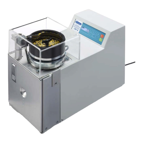
Page 7: Overview Of The Operating Components
120 ... 240 V 5 Front door 11 Compressed Protects the operator from moving parts in Device connection to the compressed the EPB-1N. The EPB-1N only works when air supply the front door is closed. connection Setting the air pressure... -
Page 8: Control Panel
Backwards (..., 3, 2, 1) When counting backwards, a checkered flag appears at 0 items. The device can no longer be started. Turn the EPB-1N off and on again. The EPB1-N changes to forwards mode. Changing the counter reading with backwards... -
Page 9: Starting Up And Operating
• Protect the compressed air hoses from heat, oil and sharp edges. Determine the cross section Check that the EPB-1N is equipped for the desired cross section. If necessary, upgrade the EPB-1N (see "Retrofitting" on page 14). 0,5 0,75 0,5 – 1,5 0,5 –... -
Page 10: Stripping And Crimping
Checking the sleeve receiver WARNING: Risk of injury! Disconnect the mains plug and the compressed air before you open the front door. • Switch off the EPB-1N with the mains switch. • Disconnect the mains plug. • Disconnect the compressed air connection. - Page 11 (1). A and B • Insert the conductor straight into the insertion funnel until it stops. As soon as the EPB-1N starts, hold the conductor with slight tension. The conductor is automatically stripped. • When the EPB-1N has stopped, pull the conductor out In the event of a malfunction or improper stripping, see page 17.
-
Page 12: Maintenance
• Check the water level in the water separator (1). If water is in the water separator: • Switch off the EPB-1N at the mains switch (2). • Disconnect the mains plug (3). • Disconnect the compressed air connection (4). -
Page 13: Adjusting And Changing The Stripping Blade
Adjusting and changing the stripping blade Removing the stripping blade WARNING: Risk of injury! Disconnect the mains plug and the compressed air before you open the front door. • Pull the release lever (1) forwards. • Remove the reversing base sleeve (2) downwards. •... - Page 14 Changing the stripping blade WARNING: Risk of injury! The stripping blades are sharp. Be careful not to injure yourself. Left blade • Unscrew the Allen screw (1) and take out the old blade (2). • Put new blade on the pin (3). •...
-
Page 15: Retrofitting
WARNING: Risk of injury! Disconnect the mains plug and the compressed air before you open the front door! • Switch off the EPB-1N with the mains switch (1). • Disconnect the mains plug (2). • Disconnect the compressed air connection (3). - Page 16 Changing the sleeve receiver The sleeve receiver must be changed every time the cross section is changed. • Remove the reversing base sleeve (see page 14). • Pull the sleeve receiver (1) upwards, remove from the holder and insert into the transport holder (2). •...
-
Page 17: Changing The Crimping Length
Changing the separation plates The separation plates must be changed during a 0.5...1.5 ↔ 2.5 cross section c hange. • Unscrew the separation plate (1) using the hexagonal wrench and remove (2) • Remove the separation plate from the retrofit kit with the desired cross section and attach in place of the previous separation plate. -
Page 18: Troubleshooting
• Check air pressure. Mains indicator (1) is not lit: • Check whether the mains plug is connected to the EPB-1N mains connection and the shock-proof plug is connected to the mains socket. • Check whether the power supply at the mains socket is O.K. -
Page 19: Start Process Is Not Being Initiated
Conductor insulation is not removed completely Check cross section • If the conductor isn't properly stripped, first check that the EPB-1N is fitted with the correct retrofit kit. • Adjust the retrofit kit to suit the selected conductor cross section (see page 14). -
Page 20: End Sleeve In-Feed Is Disrupted
Tuck the end sleeves into the transport grooves. • Change the speed of the feeder bowl. Check the baffles • Switch off the EPB-1N at the mains switch. • Unscrew the baffle covering with the hexagonal wrench. • Remove the defect end sleeves. -
Page 21: A Technical Appendix
Acoustic pressure level ( L 70 dB (A) EPB-1N is supplied with accessories tor stripping conductors and crimping end sleeves having length from 6 to 12 mm and section 0.5 to 1.5 mm². For crimping end sleeves having section 2.5 mm² or 4 mm² is necessary to use the following retrofit kits... -
Page 22: A 2 Ec Declaration Of Conformity
Nozioni fondamentali ........................2 2 Destinazione d'uso ....................22 Postazioni di lavoro ....................23 Sicurezza innanzitutto....................23 Descrizione della EPB-1N......................24 Componenti in dotazione..................24 Connettori e kit di adattamento da usare .............. 25 Visione d'insieme degli elementi di comando ............26 Pannello di comando.................... -
Page 23: Nozioni Fondamentali
La pressa EPB-1N è adatta all’utilizzo con conduttori flessibili di classe 2, 5 e 6 a norma DIN VDE 0295 e tubetti terminali Cembre serie PKE, PKC, PKD IMPORTANTE: Utilizzare esclusivamente connettori e ricambi originali. -
Page 24: Postazioni Di Lavoro
Prima di eseguire di lavori che richiedono lo sportello aperto (ad es. adattamenti, riparazioni immediate), staccare sempre la spina di alimentazione e l’aria compressa. • Durante le pause di lavoro e i periodi di inattività, staccare la EPB-1N e scollegarladall'aria compressa. • Non scollegare l'aria compressa tirando direttamente il tubo flessibile. -
Page 25: Descrizione Della Epb-1N
Descrizione della EPB-1N Componenti in dotazione Apparecchio base Tazza vibrante di alimentazione Cavo di alimentazione Chiave a brugola Alloggiamento connettore (4 pz) Modulo di ribaltamento dei connettori Imbuto di centraggio trefoli conduttore Cassetto di raccolta residui Manuale utente 10 Copertura... -
Page 26: Connettori E Kit Di Adattamento Da Usare
La pressa è adatta all’utilizzo con conduttori flessibili di classe 2, 5 e 6 a norma DIN VDE 0295 e tubetti terminali Cembre serie PKE, PKC, PKD La EPB-1N è adatta ai seguenti connettori sfusi: Tabella 2-2 Connettori utilizzabili... -
Page 27: Visione D'insieme Degli Elementi Di Comando
10 Presa di Presa per cavo di alimentazione Apertura ad Il conduttore da trattare viene inserito nella alimenta- con fusibile e interruttore integrati, imbuto per EPB-1N attraverso l'apertura ad imbuto zione alimentatore ad ampio campo l’introduzione 120... 240 V frontale. 11 Attacco... -
Page 28: Pannello Di Comando
Con il conteggio in senso decrescente, quando il numero di pezzi è uguale a 0 viene visualizzata una bandierina. È impossibile riavviare l'apparecchio. Spegnere e riaccendere la EPB-1N che passa al conteggio in senso crescente. Modifica del contatore durante il conteggio in... -
Page 29: Messa In Funzione Ed Impiego
IMPORTANTE: • Proteggere i tubi flessibili dell'aria compressa da calore, olio e spigoli vivi. Determinazione della sezione Controllare che la EPB-1N sia correttamente equipaggiata in base alla sezione prescelta. Eventualmente procedere ai necessari adattamenti (vedere “Adattamento” a pagina 14). 0,75 0,5 –... -
Page 30: Spelatura E Crimpatura
Controlli preliminari AVVERTENZA: Pericolo di infortuni! Scollegare la spina di alimentazione e l'aria compressa prima di aprire lo sportello anteriore! • Spegnere la EPB-1N mediante l'interruttore principale. • Scollegare la spina di alimentazione. • Scollegare l'attacco dell'aria compressa. •... - Page 31 (1). (A e B) • Infilare il conduttore (tenendolo diritto) nell'imbuto di alimentazione fino all'arresto. Appena la EPB-1N si avvia, tenere sempre il conduttore in leggera tensione. Il conduttore viene spelato automaticamente. • Dopo l'arresto della EPB-1N, estrarre il conduttore tenendolo diritto.
-
Page 32: Manutenzione
• Controllare il livello dell’acqua nel separatore (1). Se presente acqua nel separatore: • Spegnere la EPB-1N mediante l'interruttore principale (2). • Scollegare la spina di alimentazione (3). • Scollegare il raccordo dell'aria compressa (4). -
Page 33: Regolazione E Sostituzione Delle Lame Spelafili
Regolazione e sostituzione delle lame spelafili Smontaggio delle lame spelafili AVVERTENZA: Pericolo di infortuni! Scollegare sempre la spina di alimentazione e l'aria compressa prima di aprire lo sportello anteriore! • Tirare in avanti la leva di sbloccaggio (1). • Sfilare verso il basso il modulo di ribaltamento dei connettori (2). - Page 34 Sostituzione delle lame spelafili. AVVERTENZA: Pericolo di infortuni! Le lame spelafili sono affilate. Fare attenzione a non ferirsi. Lama sinistra • Togliere la vite a esagono incassato (1), quindi rimuovere la lama vecchia (2). • Sistemare la lama nuova sulla spina di riferimento (3). •...
-
Page 35: Adattamento
AVVERTENZA: Pericolo di infortuni! Scollegare sempre la spina di alimentazione e l'aria compressa prima di aprire lo sportello anteriore! • Spegnere la EPB-1N mediante l'interruttore principale (1). • Scollegare la spina di alimentazione (2). • Scollegare il raccordo dell'aria compressa (3). - Page 36 Sostituzione dell'alloggiamento dei connettori Sostituire l'alloggiamento dei connettori ogni volta che cambia la sezione dei conduttori. • Smontare il modulo di ribaltamento dei connettori (vedere pagina 14). • Tirare l'alloggiamento (1) verso l'alto, rimuovendolo dalla sua sedee riporlo nel supporto del coperchio (2). •...
-
Page 37: 5.2 Regolazione Della Lunghezza Di Crimpatura
Sostituzione della piastrina di separazione Sostituire la piastrina di separazione ogni volta che la sezione del conduttore passa da: 0,5 - 0,75 ↔ a 0,75 - 1,5 ↔ a 2,5. • Svitare la piastrina di separazione (1) mediante la chiave a brugola e toglierla (2). •... -
Page 38: Eliminazione Dei Guasti
Controllare la pressione dell'aria. La spia dell'alimentazione (1) è spenta: • Controllare se il connettore di alimentazione è inserito nella presa della EPB-1N e se la spina Schuko è collegata alla presa di corrente. • Controllare che la presa di corrente sia alimentata. -
Page 39: La Macchina Non Si Avvia
Controllare la sezione • Se la guaina isolante del conduttore non viene rimossa correttamente, controllare prima di tutto se la EPB-1N è dotata del kit di adattamento adeguato. • Utilizzare il kit di adattamento idoneo alla sezione prescelta (vedere pagina 14). -
Page 40: Problemi Di Alimentazione Dei Connettori
Infilare di nuovo i connettori nella chiocciola di alimentazione. • Modificare la velocità della tazza. Controllare l’intasamento del deflettore • Spegnere la EPB-1N mediante l'interruttore principale. • Svitare il deflettore mediante una chiave a brugola. • Togliere i connettori difettosi. -
Page 41: A Supplemento Tecnico
< 70 dB (A) Emissione livello pressione sonora (LpA) In dotazione alla EPB-1N sono forniti accessori per la spelatura di conduttori e la compressione di tubetti terminali di lunghezza da 6 a 12 mm e sezioni comprese fra 0.5 e 1.5 mm²... -
Page 42: A 2 Dichiarazione Di Conf Ormità Ce
Person authorised to compile the technical file: Bruno Weiland, Steinbeisstrasse 2 D-88353 Kisslegg Type of the machine: Wire stripping and crimping machine MC 40-1 (EPB-1N) Machine types: EC-Machine Directive 2006/42/EG Relevant EC-Low Voltage Directive 2006/95/EG EC directives: EC-Electromagnetic Compatibility Directive 2004/108/EG... -
Page 43: Information For Eu Member Countries
Information for EU member countries: Implementation of Directive 2011/65/EU and 2012/19/EU,on the restriction of the use of certain hazardous substances in electrical and electronic equipment and on waste disposal”. The 'not in the bin' symbol found on a device or its packaging indicates that the product must be collected separately from other waste, at the end of its useful life. - Page 44 This manual is the property of Cembre any reproduction is forbidden without written permission. Questo documento è di proprietà della Cembre: ogni riproduzione é vietata se non autorizzata per scritto. Cembre Ltd. Dunton Park West Midlands B76 9EB (Great Britain) Tel.: 01675 470440 - Fax: 01675 470220...
Need help?
Do you have a question about the EPB-1N and is the answer not in the manual?
Questions and answers