
Related Manuals for TSI Instruments SIZER 3321


Summary of Contents for TSI Instruments SIZER 3321
- Page 1 AERODYNAMIC PARTICLE SIZER SPECTROMETER ® MODEL 3321 USER’S MANUAL P/N 1930092, REVISION H SEPTEMBER 2013...
- Page 3 Product Overview Unpacking and System Setup AERODYNAMIC PARTICLE Description of the SIZER SPECTROMETER ® ™ Spectrometer MODEL 3321 ™ Spectrometer Operations USER’S MANUAL Theory of Operation Contacting Customer Service Appendixes...
- Page 4 M a n u a l H i s t o r y The following is a manual history of the Model 3321 Aerodynamic Particle ® Sizer Spectrometer (Part Number 1930092). Revision Date Preliminary March 1997 Preliminary 2 September 1997 Final November 1997 October 1998...
- Page 5 W a r r a n t y Part Number 1930092 / Revision H / September 2013 Copyright ©TSI Incorporated / 1997–2013 / All rights reserved. Address TSI Incorporated / 500 Cardigan Road / Shoreview, MN 55126 / USA Email Address particle@tsi.com World Wide Web Site www.tsi.com...
- Page 6 Service Policy Knowing that inoperative or defective instruments are as detrimental to TSI as they are to our customers, our service policy is designed to give prompt attention to any problems. If any mal- function is discovered, please contact your nearest sales office or representative, or call TSI at 1-800-874-2811- (USA) or (651) 490-2811.
- Page 7 S a f e t y This section gives instructions to promote safe and proper handling of the ® Model 3321 Aerodynamic Particle Sizer Spectrometer. There are no user serviceable parts inside the instrument. Refer all repair and maintenance to a qualified technician. All maintenance and repair information in this manual is included for use by a qualified technician.
- Page 8 7. Ground Label (inside bottom) 8. Danger High Voltage Label (Analog PC-Board) Figure 1 Location of Warning and Information Labels ® Model 3321 Aerodynamic Particle Sizer Spectrometer...
- Page 9 D e s c r i p t i o n o f C a u t i o n / W a r n i n g S y m b o l s The following symbols and an appropriate caution/warning statement are used throughout the manual and on the Model 3321 to draw attention to any steps that require you to take cautionary measures when working with the Model 3321:...
- Page 10 (This page intentionally left blank) ® viii Model 3321 Aerodynamic Particle Sizer Spectrometer...
-
Page 11: Table Of Contents
C o n t e n t s Manual History ..................ii Warranty ....................iii Safety ......................v Labels ....................v Description of Caution/Warning Symbols ........... vii Caution .................... vii Warning ................... vii Caution or Warning Symbols ............vii About This Manual ................xiii Purpose .................... - Page 12 CHAPTER 5 Theory of Operation ............5-1 Sample Flow Path ................5-1 Optics Path ..................5-3 Signal Processing Path ..............5-5 APD Module .................. 5-5 Analog Module ................5-6 Digital Module ................5-7 Particle Coincidence ................. 5-9 CHAPTER 6 Contacting Customer Service ........6-1 Technical Contacts ................
- Page 13 2-3 Serial Port Connector on the Back of the Model 3321 ....2-4 2-4 I/O Port of the Model 3321 APS™ Spectrometer ......2-5 3-1 Front Panel of the Model 3321 APS™ Spectrometer ..... 3-2 3-2 Model 3321 Menu Layout ..............3-3 3-3 Back Panel of the Model 3321 APS™...
- Page 14 (This page intentionally left blank) ® Model 3321 Aerodynamic Particle Sizer Spectrometer...
-
Page 15: Submitting Comments
A b o u t T h i s M a n u a l P u r p o s e This is an operation and service manual for the Model 3321 Aerodynamic Particle Sizer (APS ) Spectrometer. R e l a t e d P r o d u c t L i t e r a t u r e ®... - Page 16 (This page intentionally left blank) ® Model 3321 Aerodynamic Particle Sizer Spectrometer...
-
Page 17: Product Description
C H A P T E R 1 P r o d u c t O v e r v i e w This chapter contains a product description of the Model 3321 ® ™ Aerodynamic Particle Sizer (APS ) spectrometer and a brief description of how the instrument operates. -
Page 18: Applications
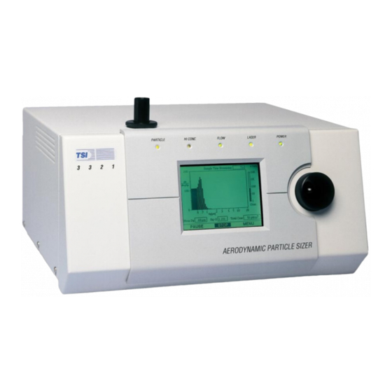
Figure 1-1 ® Model 3321 Aerodynamic Particle Sizer Spectrometer A p p l i c a t i o n s ™ The Model 3321 APS spectrometer has application in the following areas: Inhalation toxicology Atmospheric studies Ambient air monitoring ... -
Page 19: How The 3321 Operates
H o w t h e 3 3 2 1 O p e r a t e s Aerodynamic diameter is the most important size parameter because it determines a particle’s airborne behavior. The Model 3321 is specifically engineered to perform aerodynamic size measurements in real time using low particle accelerations. -
Page 20: System History
S y s t e m H i s t o r y ™ The first APS spectrometer manufactured by TSI was designated the Model 3300. It consisted of a sensor with a parallel interface to an Apple II+ computer. This sensor was the first self-contained real-time instrument to give aerodynamic particle size in the 0.5 to 15 µm range. -
Page 21: Packing List
C H A P T E R 2 U n p a c k i n g a n d S y s t e m S e t u p This chapter provides information concerning the accessories shipped with the sensor and describes basic setup procedures. -
Page 22: Mounting The Sensor
M o u n t i n g t h e S e n s o r ™ The Model 3321 APS spectrometer requires no special mounting requirements other than the ventilation requirements (see below). The cabinet has four non-marking rubber feet that give the instrument a good grip on clean, level surfaces. -
Page 23: Ventilation Requirements
Ventilation Requirements ™ The APS Sensor cabinet is designed to be cooled by room air drawn in from the sides and bottom of the cabinet and exhausted through the back of the cabinet. As shown in Figure 2-2, the cabinet should be installed with at least 2-inch (50 mm) clearance between the back panel and any other surface. -
Page 24: Power Connection
P o w e r C o n n e c t i o n Connect the AC power cord (supplied) to the AC POWER IN connection on the back of the Model 3321 and then into an available power outlet. It is not necessary to select the correct voltage, the sensor accepts line voltage of 85 to 260 VAC, 50 to 60 Hz, 100 W max., single phase. -
Page 25: I/O Port
I / O P o r t ™ The APS spectrometer has a 15-pin, D-subminiature connector port (Figure 2-4) labeled I/O PORT. This port provides three digital input and three digital output pins that can be used to control associated equipment or set device using commands described in Appendix C. - Page 26 (This page intentionally left blank) Model 3321 Aerodynamic Particle Sizer Spectrometer...
-
Page 27: Front Panel
C H A P T E R 3 D e s c r i p t i o n o f t h e A P S™ S p e c t r o m e t e r This chapter describes the front panel, back panel and internal ®... -
Page 28: Front Panel Of The Model 3321 Aps™ Spectrometer
Status LEDs Inlet Nozzle Control Knob LCD Display Figure 3-1 Front Panel of the Model 3321 APS™ Spectrometer The 320 240 pixel LCD display provides continuous real-time display of sample data. Sample data includes: Size distribution. Concentration. ... -
Page 29: Model 3321 Menu Layout
To turn the display on Press or rotate the control knob. To view information about a specific Turn the control knob so that the cursor is positioned on the bar of the channel displayed on the graph appropriate channel. The channel size and concentration are displayed at the bottom of the screen. -
Page 30: Inlet Nozzle
Inlet Nozzle The inlet nozzle on the top of the Model 3321 is designed so that aerosol can be sampled from a chamber or open air with good efficiency. Tubing can be attached to the inlet to sample when necessary. The inlet is ®... -
Page 31: Back Panel
B a c k P a n e l ™ As shown in Figure 3-3, the back panel of the APS spectrometer Model 3321 allows for power and data connections. The back panel also has a pump exhaust port and a fan. The cooling fan has a finger guard to prevent fingers, pens, etc., from being poked into the fan. -
Page 32: Dc Power Input
DC Power Input The DC power connector is a quarter-turn quick-connect entry point that ™ allows you to power the APS spectrometer with a 22 to 26 VDC (24 VDC nominal) 4A max. power source. This power could be supplied by aircraft power or two 12 VDC automotive batteries in series. -
Page 33: Serial Port
Serial Port The Serial Port is a standard RS-232 serial connection that allows ™ communications between the system computer and the Model 3321 APS spectrometer. Serial commands are sent to and from the computer to provide instrument status and collect data information. ™... -
Page 34: Bnc Connectors
BNC Connectors Three BNC connectors provide the following signals. Analog Out The Analog Out BNC connector provides a programmable analog signal that can be sent to a strip chart recorder or other analog device. Refer to Appendix C, "Using Serial Data Commands," for serial commands that control the signal output. -
Page 35: Internal Diagram Of The Model 3321 Aps™ Spectrometer
Power Digital PC-Board PC-Board Total Flow Pump Laser PC-Board Optics Analog PC-Board Sheath Flow Pump Filters Detector PC-Board Power Supply Figure 3-6 Internal Diagram of the Model 3321 APS™ Spectrometer Description of the APS Spectrometer... - Page 36 (This page intentionally left blank) 3-10 Model 3321 Aerodynamic Particle Sizer Spectrometer...
-
Page 37: Sample Setup
C H A P T E R 4 A P S™ S p e c t r o m e t e r O p e r a t i o n This chapter describes how to set up and operate the Model 3321 at the sensor using the control knob and LCD display. -
Page 38: Aps™ Spectrometer Menu
clockwise or counterclockwise until the sample time is set as desired. Then press the control knob to lock in that time. 3. Turn the control knob to select other commands or verify other settings. All of the items on the menu are described in Table 4-1. When you are finished using the menu, turn the control knob until the cursor stops on the Exit command at the top or bottom of the menu and press the control knob to return to the graphical display. -
Page 39: Baud Rate
Table 4-1 Description of Menu Items Function (see also Appendix C for serial commands Command related to Menu Items). Exit Exit the Menu and display graphical information. Sample Time [s] Set the total sample time. Can be set from 1 to 64,800 seconds (18 hours) in summed mode and from 1 to 300 seconds in average mode. -
Page 40: Collecting Data
Function (see also Appendix C for serial commands Command related to Menu Items). Laser Power [%] Displays the percent of laser power used from 0 to 100%. Default is 75%. This value is field selectable but should not be changed except for diagnostic purposes. Changing this setting will alter the calibration. -
Page 41: Sample Flow Path
C H A P T E R 5 T h e o r y o f O p e r a t i o n The Model 3321 is a time-of-flight spectrometer that measures the velocity of particles in an accelerating airflow through a nozzle. In the instrument, particles are confined to the centerline of an accelerating flow by sheath air. -
Page 42: Aerosol Flow Through The Model 3321 Aps™ Spectrometer
Aerosol In Sheath-Flow Filter Pump Filter Inner Nozzle/Sample Flow (1 L /min) Orifice Sheath-Flow Outer Nozzle/Sheath Flow Pressure (4 L /min) Transducer Accelerating T otal Flow Orifice Nozzle (5 L /min) Beam-Shaping Optics Absolute Beam Pressure Dump Total-Flow Transducer Pressure Transducer Collimated Elliptical... -
Page 43: Optics Path
O p t i c s P a t h The first component in the optics path, see Figure 5-2, is the laser diode. Light coming from the laser is polarized vertically. Using a polarization rotator (polymer half-wave plate) the polarization of the laser is rotated by 45 degrees. -
Page 44: Aps™ Spectrometer Optics Cross Section
Beam Stop Knife Edge 2nd Polarization Laser Steering Neg Cyl Lens Neg Spherical Lens Pos Spherical Lens Laser Beam Stop Calcite 1st Polarization Plate Window Polarization Laser Rotator Aperture Diode Plate Aperture Plate Detector Elliptical Mirror Detector Figure 5-2 APS™ Spectrometer Optics Cross Section ... -
Page 45: Signal Processing Path
S i g n a l P r o c e s s i n g P a t h Signal processing is performed in the APD, Analog, and Digital modules. APD Module Signal processing begins at the APD module, where scattered light from the particle is detected and converted into an analog voltage signal. -
Page 46: Analog Module
Analog Module Signals arriving at the analog module are sent to three different circuits for processing: the gate and differential circuits, and the side-scatter-intensity circuit. The output of these three circuits are then passed on to the digital module. Gate Circuit The gate circuit produces a digital gate (GATE) signal, or gate window, which represents the presence of the particle in the measurement volume. -
Page 47: Digital Module
when going through the second peak. It will stay inactive when the signal falls back to or below the difference threshold. Side-Scatter Circuit The third circuit is the side-scatter-intensity circuit. Both double crested analog signals from the low gain and the high gain outputs of the APD module are filtered, gained, clamped, and input to separate peak hold circuits, which hold the pulse height of the highest peak of each signal. - Page 48 Event 2 Is a valid particle event and occurs only when two zero crosses happen during a gate window. Both the time of flight and light-scatter intensity are recorded for this event. Detection Threshold Event 3 Is a coincident event, and occurs when three zero crosses happen during a gate window.
-
Page 49: Particle Coincidence
Uncorrelated Mode The Address PAL creates two separate addresses. One address is 10 bits and represents the type of event (1, 3, 4), or the time-of-flight (TOF) in the case of an event 2. And the second address is 6 bits and represents the light-scatter intensity for an event 2. - Page 50 (This page intentionally left blank) 5-10 Model 3321 Aerodynamic Particle Sizer Spectrometer...
-
Page 51: Technical Contacts
52068 Aachen GERMANY Telephone: +49 241-52303-0 Fax: +49 241-52303-49 E-mail: tsigmbh@tsi.com Web: www.tsiinc.de TSI Instruments Ltd. Stirling Road Cressex Business Park High Wycombe, Bucks HP12 3ST UNITED KINGDOM Telephone: +44 (0) 149 4 459200 Fax: +44 (0) 149 4 459700 E-mail: tsiuk@tsi.com... -
Page 52: Returning The Aps Spectrometer For Service
R e t u r n i n g t h e A P S S p e c t r o m e t e r f o r S e r v i c e Visit our website at http://rma.tsi.com or call TSI at 1-800-874-2811 (USA) or (651) 490-2811 for specific return instructions. -
Page 53: Maintenance Schedule
A P P E N D I X A M a i n t e n a n c e ™ Most components of the APS spectrometer are solid state and require no maintenance. This section provides information about the maintenance procedures that are required and includes a suggested maintenance schedule. -
Page 54: Cleaning The Inner Nozzle
C l e a n i n g t h e I n n e r N o z z l e Clean the nozzles according to the maintenance schedule and also under the following circumstances: The flows in the instrument are too low or erratic ™... -
Page 55: Cleaning The Outer Nozzle
When the nozzle has been cleaned satisfactorily, make sure that the o-ring still has a thin layer of grease. If not, apply a thin coating of grease. Reinsert the nozzle and make sure that it is seated firmly in the nozzle mount. - Page 56 C a u t i o n The electronic circuits within this instrument are susceptible to electro- static discharge (ESD) damage. Use ESD precautions to avoid damage. Use only a table top with a grounded conducting surface Wear a grounded, static-discharging wrist strap C a u t i o n Any time that you remove a portion of the optics assembly for cleaning, there is a chance that you can adversely affect the alignment of the...
- Page 57 The finish on the outside of the nozzle should be flat black. Remove any coating on the outer nozzle with a clean, lint-free, soft cloth and clean water. Check that the nozzle is clear by holding it up to a light and checking for a clear view through the nozzle orifice.
-
Page 58: Replacing The Filters
R e p l a c i n g t h e F i l t e r s Replace the four filters (TSI P/N 1602230) according to the maintenance schedule and under the following circumstances: If the pumps are at maximum power and still cannot achieve the correct flows for the instrument ... -
Page 59: Replacing The Eprom
Remove the tubing from each end by pushing the tubing from its end off of the filter rather than pulling the tubing off. If any of the tubing becomes damaged, replace it with an equivalent length of the same tubing. Snap the filter back into its holding clip. -
Page 60: Location Of Eprom Chips On Aps™ Spectrometer Digital Pc-Board
Switch the power off using the switch on the back of the cabinet and ™ unplug the power cord from the APS spectrometer. Remove the knurled retaining ring from the outer inlet nozzle. Loosen the six screws on both sides of the cabinet (two turns is sufficient) and remove the cover straight upward. -
Page 61: Calibrating The Aps Spectrometer
Inspect the socket to make sure that all pins are inserted into the socket. Repeat steps 8 to 13 to replace the remaining EPROM. Tilt the digital printed circuit board back down until the ribbon cable connector can be plugged back into the board. Plug in the ribbon cable connector. - Page 62 (This page intentionally left blank) A-10 Model 3321 Aerodynamic Particle Sizer Spectrometer...
-
Page 63: Troubleshooting Symptoms And Recommendations
A P P E N D I X B T r o u b l e s h o o t i n g This appendix lists potential problems and their solutions. Note: If none of the solutions provided corrects the problem, call your TSI representative for advice. - Page 64 Symptoms Recommendations The LASER LED does not come on Check to see that the laser is turned on from the front panel menu. when the instrument is powered up Rotate the control knob all the way clockwise until the menu button is shown. Press the control knob in so that the menu appears.
-
Page 65: Pin Connectors
A P P E N D I X C U s i n g S e r i a l D a t a C o m m a n d s This chapter contains information you need if you are writing your own software for a computer or data acquisition system. -
Page 66: Stop Bits And Flow Control
Table C-1 Signal Connections for RS-232 Configurations Pin Number RS-232 Signal — Transmit Output Receive Input — — — — — B a u d R a t e The baud-rate setting is the rate of communication in terms of bits per second (baud). -
Page 67: Set Commands
C o m m a n d s ™ The Model 3321 APS spectrometer uses an ASCII-based communications protocol that uses the RS-232 port of a computer to transmit commands in the form of strings. The four types of commands are: ™... - Page 68 Set Commands Read (Polled) Commands Set Baud rate Read accumulator Rb,e Set Calibration for Aerodynamic diameters Read status Flags SCAc,s Read Input from pins 1, 2, 3 and 7, 8 of the Set Calibration Label string I/O connector Set Calibration Environment Read Laser power SCEp,t Read accumulated On time of instrument...
- Page 69 S e t C o m m a n d s Set commands allow you to set up operating parameters for the Model 3321. If a set command is sent with no parameter, the current parameter is echoed. Note: Some of the commands directly affect or are affected by other commands.
-
Page 70: December
The number of channels must be at least 1 (3 calibration records: lower size, upper size, and terminator) and no more than 52 (54 calibration records). The time values correspond to accumulator time. They must be between 0.00 and 1024.00. The value 0,0 terminates the calibration array. There can be up to 52 channels of particle size requiring 54 calibration points SCA0 to SCA53. - Page 71 SCE—Set Calibration Environment SCE lets you set the temperature and pressure. SCEp,t where: p = absolute pressure at calibration (in millibars). t = absolute temperature at calibration (in degrees K). SCE with no parameters echoes the current values of p and t, which are saved in EEPROM and loaded into RAM when the instrument is powered Example: To set the absolute pressure and temperature to 970.4 millibar and...
-
Page 72: Digital Output Pin Settings
Table C-2 Digital Output Pin Settings Hex Setting Binary Equivalent Pin 13 Pin 12 Pin 11 Example: To set the outputs for I/O connector pins 11, 12, and 13 to 0 volts: To set the outputs for I/O connector pins 11, 12, and 13 to 5 volts: SF—Set Front Panel Enable SF lets you disable the front panel of the Model 3321 to prevent clearing sample averages that are being read by an external computer. - Page 73 SH—Set Hi Conc Threshold SH lets you set the conditions that will cause the HI CONC LED to light, the ™ high concentration flag to be set (see RF command), and the APS spectrometer to beep if the sound is enabled (see B command). where: x = 0 to 65535 and is the total concentration of particles, in particles/cm Note When x =0, the LED, flag, and beep are always on.
-
Page 74: Analog Voltage Output Settings
SMA—Set Mode for Analog Output SMA sets the mode and range for the analog output BNC on the back panel SMAx where: x = 0 to 6 0 = total concentration 1/cc 10 volts. 1 = total concentration 10/cc 10 volts. 2 = total concentration 100/cc 10 volts. - Page 75 SMC—Set Mode for Automatic Calibration of APD SMC lets you set the mode for automatically calibrating the Avalanche photodetector (APD) for temperature based reading of RTD command. SMCx where: x = 0 or 1 0 means that autocal is disabled. 1 means that autocal is enabled.
- Page 76 To set the sample mode to correlated data (paired) and the sample time to 60 minutes: SMT2,3600 Note: Baud rate must be set to 38,400 for correlated mode. See SB command. Baud rate can also be set from the front panel menu (see Table 4-1).
- Page 77 SV—Set Analog Output Voltage SV sets the analog output BNC voltage when configured for host mode. See SMA command. where: x = 0 to 10,000 mV Example: To set the analog output voltage to 2400 millivolts or 2.4 volts: SV2400 A c t i o n C o m m a n d s Action commands control mechanical components of the Model 3321.
- Page 78 C—Clear Buffer and Sample Time Clears the buffer, accumulator, and sample time setting. Appends a line feed (LF) character after the terminating carriage return (CR). Used only in ™ 3310 APS spectrometer mode. Refer to the command. D—Dump ™ Performs a dump or all 78 channels (3310 APS spectrometer type).
- Page 79 L—Laser Enable/Disable Enables or disables the laser. where: x is 0 or 1. L0 Disables the laser. Output power is 0. L1 Enables the laser. Output power is determined by the SL setting (see command). Q—Quick Concentration Report Produces a concentration report. This is a 3310 command. A LF is appended after the terminating CR.
-
Page 80: Read Commands (Polled
R e a d C o m m a n d s ( P o l l e d ) Read commands are polled, which means the Model 3321 sends data in response to a specific request from the computer R—Read Accumulator This is a 3310 mode command. - Page 81 Example Response 00AC 00AC can be converted to binary: 0000 0000 1010 1100 This indicates that: Internal temperature is greater than 40°C Autocal failed Excessive sample concentration Sheath flow out of range RI—Read Input From Pins 1, 2, 3 and 7, 8 of the I/O Connector Pins 1, 2, and 3 are digital inputs and are reported as a binary number 000 to 111, where a 1 indicates 5 VDC level on the pin.
- Page 82 RPI—Read Inlet Pressure Reads the current absolute inlet pressure in millibars. Example Response 1013.3 RPS—Read Sheath Delta P Reads the change in pressure across the sheath flow orifice in Pascals. Example Response 117.29 RPT—Read Total Delta P Reads the change in pressure across the nozzle flow orifice in Pascals. Example Response 130.72...
- Page 83 RR—Read Record Reads records A, B, C, D, S or Y. See description of records in following subsection. where: x = A, B, C, D, S, or Y records Note: To read C record, you must be in correlated mode (see SMT command).
- Page 84 RV—Read Firmware Version Reads the current version level of the Model 3321 firmware. Example Response Model 3321 APS Firmware Version 1.12 13-Dec- 2001 U n p o l l e d C o m m a n d s Using unpolled commands instructs the Model 3321 to automatically output data records at specific intervals.
- Page 85 UA—Generate Accumulator Report Record (Report Record A) Enables and disables reporting of Record A in unpolled operation. where: x = 1 Enables A Record x = 0 Disables A Record UA will echo current setting 0 or 1. See Record A in the “Unpolled Record Formats”...
-
Page 86: Unpolled Record Formats
UD—Generate Aerodynamic Data Report Record (Report Record D) Enables and disables reporting of Record D in unpolled operation. where: x = 1 Enables D Record x = 0 Disables D Record UD will echo current setting 0 or 1. See Record D in the “Unpolled Record Formats”... - Page 87 U n p o l l e d R e c o r d F o r m a t s The following are examples of unpolled record formats. These records are comma delimited. Accumulator (TOF) Data Record (A) CS,A,SNX,tindex,ffff,stime,dtime,evt1,evt3,evt4,total,a1,a2,a3,... an (the record is not available in Averaging or Correlated modes) = Checksum = Accumulator (TOF) Data Record...
- Page 88 SS Accumulator Data Record (B) CS,B,SNX,tindex,ffff,stime,dtime,ev1,evt3,evt4,total,b1,b2,b3,... bn (the record is not available in Averaging or Correlated modes) = Checksum = Side Scatter Accumulator Data Record = S for Summed Mode C Correlated mode = N for normal operation A if in autocal mode D if in autocal and autocal was “done”...
- Page 89 Correlated (Paired) Data Record (C) The C record is a multi-record report with a header (C0) followed by n more records (C1...Cn) CS,C,0,PNX,tindex,ffff,stime,dtime,evt1,evt3,evt4,total,n,m (the C records only available in Correlated mode) = Checksum = Correlated (Paired) Data Record = 0 indicates header record for C data report = C for Correlated Mode = N for normal operation A if in autocal mode...
- Page 90 Aerodynamic (TOF) Data Record (D) CS,D,ANX,tindex,ffff,stime,dtime,evt1,evt3,evt4,total,d1,d2,d3,... dn = Checksum = Aerodynamic Data Record = A for Averaging Mode S for Summed Mode C for Correlated Mode = N for normal operation A if in autocal mode D if in autocal and autocal was “done” at the beginning of this sample = X for spare position tindex...
-
Page 91: How To Input Commands And Troubleshoot The Results
Auxiliary Data Record (Y) CS,Y,bpress,tflow,sflow,a0,a1,d0,d1,d2,lpower,lcur,spumpv,tpumpv,itemp, btemp,dtemp,Vop = Checksum = Auxiliary Data Record bpress = barometric inlet pressure (average over sample time) tflow = total flow (average over sample time) sflow = sheath flow (average over sample time) = Analog input voltage 0(I/O connector pin 7 ref to pin 15 (average over sample time) = Analog input voltage 1(I/O connector pin 8 ref to pin 15 (average over sample time) -
Page 92: Input Guidelines
Troubleshooting Input Use Table C-4 as a troubleshooting guide. Table C-4 Troubleshooting Serial Commands Symptom Possible Problem Refer to "Error" message An invalid command; command does not Figure C-2 in this section. after pressing exist. <Enter> An invalid parameter, which includes too The command showing the range and many parameters or a parameter that is out- an example. -
Page 93: Specifications Of The Model 3321 Aerodyamic Particle Sizer
A P P E N D I X D M o d e l 3 3 2 1 S p e c i f i c a t i o n s The following specifications—which are subject to change—list the most important features of the Model 3321. - Page 94 Weight ..........10 kg (22 lb.). Fuse (not replaceable by user) (internal to power supply -- not accessible by operator) ......~T 6.3A SB/250V TSI and TSI logo are registered trademarks of TSI Incorporated. Model 3321 Aerodynamic Particle Sizer Spectrometer...
- Page 95 I n d e x Aerodynamic Particle Sizer differential circuit, 5-6 Spectrometer, (continued) digital, 5-8 AC power connector, 3-5 ventilation requirements, 2-3 digital module, 5-7 accumulator (TOF) data record analog module, 5-6 correlated mode, 5-9 (A), C-23 differential circuit, 5-6 event 1, 5-7 action commands, C-4, C-13 gate circuit, 5-6...
- Page 96 indicators, 3-4 read accumulator, C-16 serial data commands (continued) inlet nozzle, 3-4 read aerosol sample flow, C-18 unpolled record formats. (see internal components, 3-8 read commands (polled) also unpolled record formats) internal diagram of APS, 3-9 read accumulated on time, C-17 serial port, 3-7 read accumulator, C-16 serial port connector, 2-4...
- Page 97 uncorrelated mode, 5-9 unpacking, 2-1 unpolled commands, C-4, C-20 begin unpolled operation, C-20 disable all records, C-20 enable all records, C-20 generate accumulator report record (report record A), C-21 generate aerodynamic data report record (report record D), C-22 generate auxiliary report record (report record Y), C-22 generate correlated (paired) report record (report record...
-
Page 99: Reader's Comments
R e a d e r ’ s C o m m e n t s Please help us improve our manuals by completing and returning this questionnaire to the address listed in the “About This Manual” chapter. Feel free to attach a separate sheet of comments. ®... - Page 101 TSI Incorporated – Visit our website www.tsi.com for more information. Tel: +1 800 874 2811 India Tel: +91 80 67877200 Tel: +44 149 4 459200 China Tel: +86 10 8219 7688 France Tel: +33 4 91 11 87 64 Singapore Tel: +65 6595 6388 Germany Tel: +49 241 523030...
Need help?
Do you have a question about the SIZER 3321 and is the answer not in the manual?
Questions and answers