Table of Contents
Advertisement
Quick Links
Proportional flow control valve
VPCF-6-L-8-...
Operating instructions
Original: de
Proportional flow control valve VPCF-6-L-8...
1
Safety
1.1 Use for intended purpose
The proportional flow control valve VPCF-6-L-8-... is intended for regulation of a
flow proportional to a specified setpoint value.
The flow control valve is intended for use in an industrial environment. Outside of
industrial environments, e.g. in commercial and mixed-residential areas, actions to
suppress interference may have to be taken.
1.2 Safety instructions
• Use the flow control valve only in its original status without unauthorised modi
fications.
• Use the flow control valve only in an excellent technical status.
• Comply with all applicable national and international regulations.
• Comply with specified limits (è Chapter 12, Technical data).
• Take into consideration the ambient conditions at the location of use.
1.3 Training of skilled personnel
Only qualified personnel may perform installation, commissioning, maintenance
and disassembly of the flow control valve. The qualified personnel must be familiar
with installation and operation of electrical and pneumatic control systems.
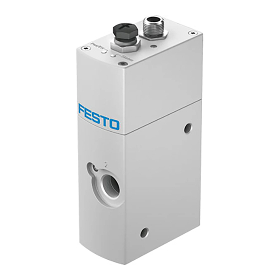
2
Structure
aA
7
aJ
9
8
7
1
Electrical connection, plug M12
2
Service interface, sealed with cover
cap (only for Festo service staff)
3
Air port (2)
4
Threaded holes M5 (10 mm deep)
for mounting of the flow control
valve, è Fig. 6
5
Hole for earth connection (FE),
è Fig. 6
Fig. 1
Festo AG & Co. KG
Postfach
73726 Esslingen
Germany
+49 711 347-0
www.festo.com
8066867
1611a
[8066869]
. . . . . . . . . . . . . . . . . . . . . . .
English
6
6
5
6
Through-holes for mounting the
flow control valve
7
Threaded holes M5 (10 mm deep)
for mounting of the flow control
valve
8
Exhaust air port (3)
9
Hole for earth connection (FE)
aJ
Compressed air port (1)
aA
LEDs
3
Product variants
Characteristic
Basic function
Nominal width
Valve type
Valve function
Pneumatic port
Pressure range
Setpoint specification
Display type
EU certification
Fig. 2
4
The flow control valve is a proportional directional control valve with integrated
flow regulator. The flow regulator determines the current flow, based on its intern
al measured values, and compares it to the setpoint value. If the current value
deviates from the setpoint, the valve is actuated until the flow has reached the
setpoint value.
Fig. 3
5
Transport and storage
• Store the product in a dry, UV- and corrosion-protected environment. Ensure
storage times are short.
6
Installation
6.1 Mechanical installation
• Make sure there is sufficient space for the connecting line and tubing connec
tions. In this way you will prevent the connecting lines and the tubes from being
broken.
• Place the flow control valve as close as possible to the consumer. This leads to
improved control precision and shorter response times.
Mounting options of the flow control valve:
– Through-hold mounting through 2 lateral through-holes
– Direct mounting through 4 threaded holes (M5x10 mm) on the underside of the
1
flow control valve
– Direct mounting through 4 threaded holes (M5x10 mm) on the front side of the
2
flow control valve
Through-hole fastening
Side
3
4
1
1
Screw M6 (2x) for through-hole fastening
2
Screw M5 (4x) for direct mounting
Fig. 4
• Fasten flow control valve with screws 1 or 2.
– Observe the tightening torque (è Fig. 5).
– In the case of direct mounting from below or from the front: Also observe the
maximum screw-in depth (è Fig. 5).
Type of mounting
Through-hole fastening
Direct mounting from below
Direct mounting on the front
Fig. 5
Type code
Description
VPCF
Propor tional flow control valve
6
6 mm
L
In-line valve
8
3/3-way valve
G38
G3/8
6
0 ... 6 bar
10
0 ... 10 bar
V1
Voltage variant 0 ... 10 V
A4
Current variant 4 ... 20 mA
E
LED
EX2
II 3G, II 3D
Direct mounting
Bottom
Front
2
Tightening torque [Nm]
Max. screw-in depth [mm]
Max. 9 Nm
–
5 Nm
10 mm
5 Nm
10 mm
2
Advertisement
Table of Contents

Subscribe to Our Youtube Channel
Related Manuals for Festo VPCF-6-L-8 Series


Summary of Contents for Festo VPCF-6-L-8 Series
- Page 1 Screw M6 (2x) for through-hole fastening Service interface, sealed with cover flow control valve Screw M5 (4x) for direct mounting cap (only for Festo service staff) Threaded holes M5 (10 mm deep) Fig. 4 Air port (2) for mounting of the flow control...
- Page 2 An input menu for calculating flow and pressure loss with specified tube length/tube diameter can be found on the Festo Website. è www.festo.com/conversion è “Flow calculation” selection field Drill hole for functional earth ’...
- Page 3 (at the analogue input). Accessories DIn1 No error status Flow control valve switches into the ventila è www.festo.com/catalogue tion mode. DIn1 Error status Error is acknowledged and the driver is switched back on via a rising edge at the di...
- Page 4 +15 … +35 Technical data Storage [°C] –20 … +70 CE marking In accordance with EU EMC Directive (Declaration of conformity è www.festo.com/sp) In accordance with EU Explosion Protection Directive (ATEX) Nominal operating voltage [V DC] Operating voltage range [V DC] 20.4 …...
Need help?
Do you have a question about the VPCF-6-L-8 Series and is the answer not in the manual?
Questions and answers