Table of Contents
Advertisement
Quick Links
Advertisement
Table of Contents

Related Manuals for Siko AP10T


Summary of Contents for Siko AP10T
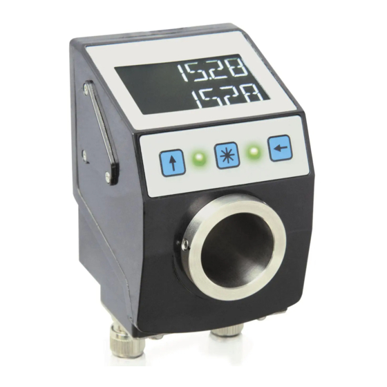
- Page 1 AP10T Set point display with CANopen interface User manual 321/17...
-
Page 2: Table Of Contents
4.3.1 Transfer of Process Data Objects (PDO) ..............14 4.3.1.1 Receive-PDO (from Master to AP10T) ..............14 4.3.1.2 Transmit PDO (from AP10T to the master) ............15 4.3.2 Control word ...................... 16 4.3.3 Status word ......................16 Parameter data exchange ..................17 4.4.1... - Page 3 4.7.2.28 5000h: Diagnosis of CAN bus errors ..............49 4.7.2.29 5F09h: External Heartbeat timer and external Heartbeat source ......49 4.7.2.30 5F0Ah: Node-ID, Auto-ID and Baud rate Bus CAN ..........50 AP10T Date: 27.10.2017 Art. No. 88125 Mod. status 321/17...
- Page 4 4.7.2.42 6505h: Warnings ..................... 59 4.7.2.43 6506h: Supported Warnings ................59 4.7.2.44 6507h: Profile and Software Version ..............59 4.7.2.45 6508h: Operating Time ..................60 4.7.2.46 650Bh: Serial Number ..................60 AP10T Date: 27.10.2017 Art. No. 88125 Mod. status 321/17 Page 4 of 60...
-
Page 5: General Informaton
Switching on the supply voltage The AP10T will be initialized after switching on the supply voltage. A display test is executed during initialization, the LEDs are lighted consecutively and the configuration parameters are loaded from the non-volatile memory into the RAM of the controller. -
Page 6: Brief Description
-199999 and -999999, then the negative sign and the digit of the highest order will flash alternately. If the value range drops below -99999, " " will be displayed. AP10T Date: 27.10.2017 Art. No. 88125 Mod. status 321/17 Page 6 of 60... -
Page 7: Led Display
The set point display can be completely parameterized via the bus interface. The most significant bus parameters (node address and baud rate) can be parameterized manually by means of the keyboard. AP10T Date: 27.10.2017 Art. No. 88125 Mod. status 321/17... -
Page 8: Manual Parameterization
250 kbaud 500 kbaud 800 kbaud 1000 kbaud CODE System commands Load factory settings (see chapter 3.8.1) Start diagnosis (see chapter 3.8.2) Table 2: Manually adjustable parameters AP10T Date: 27.10.2017 Art. No. 88125 Mod. status 321/17 Page 8 of 60... -
Page 9: Parameterization Via Interface
Display Parameter address Parameter 5F0Ah Node-ID KBAUD 5F0Ah Baud rate 1005h COB-ID SYNC 100Ch Guard Time 100Dh Life Time Factor 1014h COB-ID Emergency 1017h Heartbeat timer value AP10T Date: 27.10.2017 Art. No. 88125 Mod. status 321/17 Page 9 of 60... -
Page 10: Diagnosis
The CiA DS-301 V4.2 CANopen communication profile as well as the Device profile for Encoders CiA DS-406 V3.2 form the basis for AP10T, which supports device class C2. As this device is beyond the scope of an encoder's functionality, communication partly differs from the above- mentioned device profile. - Page 11 5F0Ah: Node-ID, Auto-ID and Baud rate Bus CAN) is assigned in every bus system once while AP10T is being configured. Node-ID = 0 is reserved and must not be used; thus the node numbers are in the range of 1 to 127.
-
Page 12: Node Control
"INITIALISATION", "PRE-OPERATIONAL", "OPERATIONAL" or "STOPPED" (see Fig. Power on or software reset Re-initialization CAN-card Init Initialization CAN-communication BootUp Message Fig. 2: NMT status diagram AP10T Date: 27.10.2017 Art. No. 88125 Mod. status 321/17 Page 12 of 60... -
Page 13: Nmt Communication Statuses
OPERATIONAL / PRE-OPERATIONAL / INITIALISATION STOPPED (Reset Communication) Table 6: Switching between communication statuses If transmitted as Node-ID x = 0, the message is intended for all bus subscribers. AP10T Date: 27.10.2017 Art. No. 88125 Mod. status 321/17 Page 13 of 60... -
Page 14: Boot-Up
Process data objects (PDO) serve for quick process data exchange. A maximum of 8 bytes of user data can be transferred in a PDO. AP10T supports the Receive-PDO services RPDO1 and RPDO2 according to Draft Standard 301 as well as the Transmit-PDO services TPDO1 and TPDO2 according to Draft Standard 301 and Device Profile 406. -
Page 15: Transmit Pdo (From Ap10T To The Master)
Set point2 in the lower row. 4.3.1.2 Transmit PDO (from AP10T to the master) PDO transfer from the display to the bus master (TPDO) can be initiated as a result of various events: ... -
Page 16: Control Word
LED blinking Table 10: Control word 4.3.3 Status word The status word indicates the current status of AP10T. It consists of 16 bits and is mapped in the object 5F19h: Status word as well as in the two Transmit-PDOs. Status word... -
Page 17: Parameter Data Exchange
(parameters) + Node-ID index Command byte, Byte 0: The command byte determines the type of access and the number of valid data bytes. The following command bytes are valid for AP10T: Command byte Type Function Write Request SDO (rx), Initiate Download... -
Page 18: Error Response
Response, expedited (1 byte from 4 data bytes valid) Error Response SDO (tx), Abort Domain AP10T reports error code to master Transfer Table 12: Command coding Index, bytes 1 and 2: The index (object number) is entered in user data byte 2 (low byte) and in in user data byte 3 (high byte) in the Intel data format. -
Page 19: Examples Of Sdo Access
Example of writing SDO parameters: Change the display orientation stored with 1 byte in object 5F12h, sub-index 1 of the objects directory in the AP10T with device address 1. Calculation of the identifier: 600h + Node-ID = 600h + 1 = 601h... -
Page 20: Node Monitoring
The identifier of the emergency object is set to 80h + Node-ID by default; however, it can be changed via object 1014 h (see 1014h: COB-ID Emergency Message). Transmission of an emergency message is only possible in the "OPERATIONAL" or "PRE-OPERATIONAL" NMT statuses. AP10T Date: 27.10.2017 Art. No. 88125 Mod. status 321/17 Page 20 of 60... -
Page 21: Node Guarding
The master monitors the status of the slave device via the Heartbeat protocol. While doing this, the unit sends cyclically its NMT status. The AP10T is a heartbeat producer, it does not receive nor process heartbeat protocols. The cycle time of the heartbeat message is set via object 1017h. -
Page 22: External Heartbeat
This function facilitates first commissioning of the devices in the plant. The baud rate is factory-set to "Auto Baud". AP10T "overhears" the bus and does not transmit messages. To enable the instrument's autonomous recognition and adjustment of the prevalent bus baud rate, communication must take place on the CAN bus. -
Page 23: Auto-Id
If so, the procedure may be repeated until all devices have received the desired Node-ID. The Auto-ID function is aborted in the AP10T when an illegal value was sent for the new ID. SDO Abort messages will be returned in this case. - Page 24 Communication via CAN bus (CANopen) Fig. 3: Auto-ID function AP10T Date: 27.10.2017 Art. No. 88125 Mod. status 321/17 Page 24 of 60...
-
Page 25: Directory Of Objects
1A01h: 2. Transmit PDO Mapping Describes the arrangement of the objects mapped in Parameter TPDO2. Setting whether calibration of the display is enabled 2003h: key actuation enable via key operation. AP10T Date: 27.10.2017 Art. No. 88125 Mod. status 321/17 Page 25 of 60... - Page 26 6508h: Operating Time Counter of operating hours (function is not supported) 650Bh: Serial Number Outputs the value FFFFFFFFh (function is not supported). Table 16: Overview of objects AP10T Date: 27.10.2017 Art. No. 88125 Mod. status 321/17 Page 26 of 60...
-
Page 27: Description Of Objects
Encoder type Byte 0 Byte 1 Byte 2 Byte 3 0196h (= 406): CANopen Device Profile for Encoders, Version 3.02 0000h: AP10T is not an encoder. 4.7.2.2 1001h: Error Register Object 1001h indicates the error state of the device. Sub-index Description... -
Page 28: 1002H: Manufacturer Status Register
Access PDO mapping Data type UNSIGNED 8 Default EEPROM Sub-index 01h-08h Description error messages that occurred Access PDO mapping Data type UNSIGNED 32 Default EEPROM AP10T Date: 27.10.2017 Art. No. 88125 Mod. status 321/17 Page 28 of 60... -
Page 29: 1005H: Cob-Id Sync Message
Object 1008h indicates the device name. Sub-index Description Device name as ASCII characters Access Const PDO mapping Data type Visible_String Default AP10T EEPROM Data content Byte 0 Byte 1 Byte 2 Byte 3 41h ("A") 50h ("P") 31h ("1") 30h ("0") AP10T Date: 27.10.2017... -
Page 30: 1009H: Manufacturer Hardware Version
Guarding). The cycle time is indicated in milliseconds. The value "0" means that Node Guarding is deactivated. Sub-index Description Guard Time Access PDO mapping Data type UNSIGNED 16 Default EEPROM AP10T Date: 27.10.2017 Art. No. 88125 Mod. status 321/17 Page 30 of 60... -
Page 31: 100Dh: Life Time Factor
76h ("v") 65h ("e") Read: Bit 31 … 2 0, reserved Bit 1 0: device does not save parameters autonomously Bit 0 1: unit stores parameter by command AP10T Date: 27.10.2017 Art. No. 88125 Mod. status 321/17 Page 31 of 60... - Page 32 76h ("v") 65h ("e") Read: Bit 31 … 2 0, reserved Bit 1 0: device does not save parameters autonomously Bit 0 1: unit stores parameter by command AP10T Date: 27.10.2017 Art. No. 88125 Mod. status 321/17 Page 32 of 60...
-
Page 33: 1011H: Restore Parameter
Byte 2 Byte 3 6Ch ("l") 6Fh ("o") 61h ("a") 64h ("d") Read: Bit 31 … 1 0, reserved Bit 0 1: unit permits loading of default parameters AP10T Date: 27.10.2017 Art. No. 88125 Mod. status 321/17 Page 33 of 60... - Page 34 Byte 2 Byte 3 6Ch ("l") 6Fh ("o") 61h ("a") 64h ("d") Read: Bit 31 … 1 0, reserved Bit 0 1: unit permits loading of default parameters AP10T Date: 27.10.2017 Art. No. 88125 Mod. status 321/17 Page 34 of 60...
-
Page 35: 1014H: Cob-Id Emergency Message
0: if bit 29 = 0 X: bits 28 – 11 of the EMCY-COB-ID, if bit 29 = 1 Bit 10 … 0 X: bits 10 – 0 of the EMCY -COB-ID AP10T Date: 27.10.2017 Art. No. 88125 Mod. status 321/17... -
Page 36: 1017H: Producer Heartbeat Time
Access PDO mapping Data type UNSIGNED 8 Default EEPROM Sub-index Description the manufacturer identification number (vendor ID) for the company SIKO GmbH allocated by the CiA Access PDO mapping Data type UNSIGNED 32 Default 195h EEPROM... -
Page 37: 1200H: Server Sdo Parameter
PDO mapping Data type UNSIGNED 8 Default EEPROM Sub-index Description COB-ID Client -> Server (rx) Access PDO mapping Data type UNSIGNED 32 Default 00000600h + Node-ID EEPROM AP10T Date: 27.10.2017 Art. No. 88125 Mod. status 321/17 Page 37 of 60... -
Page 38: 1400H: 1. Receive Pdo Parameter
UNSIGNED 32 Default 200h + Node-ID EEPROM Sub-index Description Transmission Type Access PDO mapping Data type UNSIGNED 8 Default EEPROM Data content 0h … F0h, FEh, FFh AP10T Date: 27.10.2017 Art. No. 88125 Mod. status 321/17 Page 38 of 60... -
Page 39: 1401H: 2. Receive Pdo Parameter
Description COB-ID of the PDO2 Access rw (writable in the "Pre-Operational" state only see chapter 4.1) PDO mapping Data type UNSIGNED 32 Default 300h + Node-ID EEPROM AP10T Date: 27.10.2017 Art. No. 88125 Mod. status 321/17 Page 39 of 60... -
Page 40: 1600H: 1. Receive Pdo Mapping Parameter
Object 1600h determines the objects that are mapped on the first Receive PDO (RPDO1). Sub-index Description number of objects mapped Access PDO mapping Data type UNSIGNED 8 Default EEPROM AP10T Date: 27.10.2017 Art. No. 88125 Mod. status 321/17 Page 40 of 60... -
Page 41: 1601H: 2. Receive Pdo Mapping Parameter
Object 1601h determines the objects that are mapped on the second Receive PDO (RPDO2). Sub-index Description number of objects mapped Access PDO mapping Data type UNSIGNED 8 Default EEPROM AP10T Date: 27.10.2017 Art. No. 88125 Mod. status 321/17 Page 41 of 60... -
Page 42: 1800H: 1. Transmit Pdo Parameter
According to DS406, TPDO1 is used for asynchronous PDO transmission. The communication parameters are set for TPDO1 via object 1800h. Sub-index Description indicates the largest sub-index supported Access PDO mapping Data type UNSIGNED 8 Default EEPROM AP10T Date: 27.10.2017 Art. No. 88125 Mod. status 321/17 Page 42 of 60... - Page 43 The service is disabled by writing the value 0. The content of this object is identical with object 6200h. If the value is changed while the timer is running, then the change will take effect only with the next timer run. AP10T Date: 27.10.2017 Art. No. 88125 Mod.
-
Page 44: 1801H: 2. Transmit Pdo Parameter
PDO is sent after receipt of 1 ... 240 SYNC messages. FFh (255) FDh (253) Device responds to RTR-request only if RTR Bit 30 is enabled in the COB-ID. AP10T Date: 27.10.2017 Art. No. 88125 Mod. status 321/17 Page 44 of 60... -
Page 45: 1A00H: 1. Transmit Pdo Mapping Parameter
PDO1 message (Data byte 0 until 3) Access PDO mapping Data type UNSIGNED 32 Default 5F160320h (Set point object 5F16h, Sub-index 0x03, 32bit) EEPROM AP10T Date: 27.10.2017 Art. No. 88125 Mod. status 321/17 Page 45 of 60... -
Page 46: 1A01H: 2. Transmit Pdo Mapping Parameter
PDO2 message (Data byte 0 until 3) Access PDO mapping Data type UNSIGNED 32 Default 5F160120h (Set point object 5F16h, Sub-index 0x01, 32bit) EEPROM AP10T Date: 27.10.2017 Art. No. 88125 Mod. status 321/17 Page 46 of 60... -
Page 47: 2003H: Key Actuation Enable
The object 2004h indicates whether the actuation of the key is enabled. Sub-index Description key enable Access PDO mapping Data type UNSIGNED 8 Default EEPROM Data content 0: actuation disabled 1: actuation enabled AP10T Date: 27.10.2017 Art. No. 88125 Mod. status 321/17 Page 47 of 60... -
Page 48: 2005H: Configuration Enable Via Keyboard And Delay Of Start Of Configuration
1: enabled Sub-index Description delay of start of configuration (key enable time) Access PDO mapping Data type UNSIGNED 8 Default EEPROM Data content 1 … 60 s AP10T Date: 27.10.2017 Art. No. 88125 Mod. status 321/17 Page 48 of 60... -
Page 49: 5000H: Diagnosis Of Can Bus Errors
CAN bus. Sub-index Description indicates the largest sub-index supported Access PDO mapping Data type UNSIGNED 8 Default EEPROM AP10T Date: 27.10.2017 Art. No. 88125 Mod. status 321/17 Page 49 of 60... -
Page 50: 5F0Ah: Node-Id, Auto-Id And Baud Rate Bus Can
Via object 5F0Ah, Node-ID, Auto-ID (see chapter 4.6.2: Auto-ID) and the baud rate of the bus (see chapter 4.6.1: Auto-Baud) can be set. Sub-index Description indicates the largest sub-index supported Access PDO mapping Data type UNSIGNED 8 Default EEPROM AP10T Date: 27.10.2017 Art. No. 88125 Mod. status 321/17 Page 50 of 60... - Page 51 UNSIGNED 8 Default 0 (Auto baud) EEPROM Data content 0: Auto baud 1: 125 kbaud 2: 250 kbaud 3: 500 kbaud 4: 800 kbaud 5: 1000 kbaud AP10T Date: 27.10.2017 Art. No. 88125 Mod. status 321/17 Page 51 of 60...
-
Page 52: 5F0Bh: Display In The 2
The object 5F11h indicates the number of decimal places. Sub-index Description number of decimal places Access PDO mapping Data type UNSIGNED 8 Default EEPROM Data content 0 … 4 AP10T Date: 27.10.2017 Art. No. 88125 Mod. status 321/17 Page 52 of 60... -
Page 53: 5F12H: Display Orientation And Leds
EEPROM Data content 0: Off 1: acknowledgement-dependent Sub-index Description LED2 red left Access PDO mapping Data type UNSIGNED 8 Default EEPROM Data content 0: Off 1: acknowledgement-dependent AP10T Date: 27.10.2017 Art. No. 88125 Mod. status 321/17 Page 53 of 60... - Page 54 Default EEPROM Data content 0: Off 1: On Sub-index Description backlight white Access PDO mapping Data type UNSIGNED 8 Default EEPROM Data content 0: Off 1: On AP10T Date: 27.10.2017 Art. No. 88125 Mod. status 321/17 Page 54 of 60...
-
Page 55: 5F16H: Read Target Value
Access PDO mapping Data type UNSIGNED 8 Default EEPROM Sub-index Description Set point2 (4 LSB Bytes) Access PDO mapping Data type UNSIGNED 32 Default EEPROM AP10T Date: 27.10.2017 Art. No. 88125 Mod. status 321/17 Page 55 of 60... -
Page 56: 5F19H: Status Word
Object 5F19h informs about the current device status (see chapter 4.3.3: Status word). Sub-index Description The status word informs about the current device status. Access PDO mapping Data type UNSIGNED 16 Default EEPROM AP10T Date: 27.10.2017 Art. No. 88125 Mod. status 321/17 Page 56 of 60... -
Page 57: 5F1Bh: Sensor Type And Operating Mode
The respective key actuation enable can be set as well. Sub-index Description acknowledgement settings Access PDO mapping Data type UNSIGNED 8 Default EEPROM Data content - and front key 1: only front key - and -key AP10T Date: 27.10.2017 Art. No. 88125 Mod. status 321/17 Page 57 of 60... -
Page 58: 6200H: Cycle Timer
This object 6504h indicates the alarm messages that are supported. The relevant bits are set. Sub-index Description supported alarm messages Access PDO mapping Data type UNSIGNED 16 Default 3001h EEPROM Data content Bit 15 … 0 not used AP10T Date: 27.10.2017 Art. No. 88125 Mod. status 321/17 Page 58 of 60... -
Page 59: 6505H: Warnings
Profile and software version Access PDO mapping Data type UNSIGNED 32 Default 01000302h EEPROM Profile version Software version Byte 0 (LSB) Byte 1 Byte 2 Byte 3 (MSB) AP10T Date: 27.10.2017 Art. No. 88125 Mod. status 321/17 Page 59 of 60... -
Page 60: 6508H: Operating Time
Object 650Bh outputs the serial number of the encoder. This function is not supported. Sub-index Description Serial number Access PDO mapping Data type UNSIGNED 32 Default FFFFFFFFh EEPROM AP10T Date: 27.10.2017 Art. No. 88125 Mod. status 321/17 Page 60 of 60...
Need help?
Do you have a question about the AP10T and is the answer not in the manual?
Questions and answers