Table of Contents
Advertisement
Available languages
Available languages
Quick Links
Download this manual
See also:
User Manual
Advertisement
Chapters
Table of Contents

Related Manuals for Siko AP10T


Summary of Contents for Siko AP10T
- Page 1 AP10T Sollwertanzeige Deutsch Originalmontageanleitung Seite 2 Setpoint display English Translation of the Original Installation Instructions page 16 154/16...
-
Page 2: Table Of Contents
5 Inbetriebnahme 6 Transport, Lagerung, Wartung und Entsorgung 7 Zubehör Anschluss-Stecker 7.1 Gegenstecker M8 gerade inkl. Kabel 7.2 Gegenstecker M8 gerade 7.3 Gegenstecker M8 BUS-Abschluss 8 Technische Daten AP10T · Datum 19.05.2016 · Art. Nr. 88088 · Änd. Stand 154/16... -
Page 3: Dokumentation
2 Sicherheitshinweise 2.1 Bestimmungsgemäße Verwendung Die Sollwertanzeige AP10T dient als Anzeige von Sollwerten z. B. zur For- matverstellung. Die Sollwertanzeige ist nur für die Verwendung im Indust- riebereich vorgesehen, die keinen besonderen elektrischen oder mechani- schen Sicherheitsanforderungen unterliegen. -
Page 4: Zielgruppe
Geräte/Systeme gemäß den Standards der Sicherheitstech- nik in Betrieb zu nehmen, zu erden und zu kennzeichnen. 2.4 Grundlegende Sicherheitshinweise Explosionsgefahr GEFAHR ` Sollwertanzeige nicht in explosionsgefährdeten Zonen einsetzen. AP10T · Datum 19.05.2016 · Art. Nr. 88088 · Änd. Stand 154/16... -
Page 5: Identifikation
Herstellerbezeichnung eines geeigneten Drehmoment- schlüssels auf Anfrage erhältlich. Anzugsmoment: 0.4 Nm Ist die Verwendung des Drehmomentschlüssels aufgrund der Montagesitu- ACHTUNG ation nicht möglich, ist die elektrische Installation vor der mechanischen Montage durchzuführen. AP10T · Datum 19.05.2016 · Art. Nr. 88088 · Änd. Stand 154/16... -
Page 6: Mechanische Montage
` Anschlussverbindungen nicht unter Spannung schließen oder lösen. ` Verdrahtungsarbeiten spannungslos durchführen. ` Litzen mit geeigneten Aderendhülsen versehen. ` Vor dem Einschalten sind alle Leitungsanschlüsse und Steckverbindun- gen zu überprüfen. AP10T · Datum 19.05.2016 · Art. Nr. 88088 · Änd. Stand 154/16... - Page 7 Fehlerhafte oder fehlende Terminierung VORSICHT Eine fehlerhafte oder fehlende Terminierung, bzw. Pegelfestlegung führt zu Kommunikationsfehlern oder kann die Elektronik der Anzeige zerstören. ` Terminierung korrekt ausführen und prüfen. AP10T · Datum 19.05.2016 · Art. Nr. 88088 · Änd. Stand 154/16...
- Page 8 Bus AUS: Buchse 4 pol. M8 (siehe Zubehör Gegenstecker und Kabelverlängerungen siehe Kapitel 7. Belegung Bus-Ein Bus-Aus DÜB/CANL DÜA/CANH Ansichtseite = Steckseite AP10T · Datum 19.05.2016 · Art. Nr. 88088 · Änd. Stand 154/16...
- Page 9 4). Verwenden Sie dazu 6.3 mm Flachstecker oder Kabelschuh mit kurzer Litze 2.5 … 4 mm² (nicht im Lieferumfang). Bei mehreren Sollwert- anzeigen wird empfohlen die Erdung auf eine PE-Schiene anzuschlie- Abb. ßen (siehe AP10T · Datum 19.05.2016 · Art. Nr. 88088 · Änd. Stand 154/16...
-
Page 10: Inbetriebnahme
Ein empfangener Sollwert wird bis zur Quittierung (Quittierungstaste) blinkend dargestellt und mit einer roten LED signalisiert. Sobald die Quit- tierung vorliegt steht der Wert permanent im Display und die entspre- chende grüne LED leuchtet. AP10T · Datum 19.05.2016 · Art. Nr. 88088 · Änd. Stand 154/16... - Page 11 Wird keine Taste betätigt, so wird der Konfi- gurations-Modus nach ~30 s verlassen, ohne dass der zuletzt angezeigte Wert gespeichert wird, d. h. der ursprüngliche Wert bleibt erhalten. AP10T · Datum 19.05.2016 · Art. Nr. 88088 · Änd. Stand 154/16...
-
Page 12: Transport, Lagerung, Wartung Und Entsorgung
Sollwertanzeigen sorgfältig behandeln, transportieren und lagern. Hierzu sind folgende Punkte zu beachten: • Sollwertanzeigen in der ungeöffneten Originalverpackung transpor- tieren und/oder lagern. • Sollwertanzeigen vor schädlichen physikalischen Einflüssen wie Staub, Hitze und Feuchtigkeit schützen. AP10T · Datum 19.05.2016 · Art. Nr. 88088 · Änd. Stand 154/16... -
Page 13: Zubehör Anschluss-Stecker
2. Kabel abmanteln. 3. Schirm kürzen, aufweiten und um Schirmring legen. 4. Litzen durch Kupplungshülse fädeln und abisolieren. 5. Teile montieren. Druckschraube andrehen um das Kabel zu fixieren. AP10T · Datum 19.05.2016 · Art. Nr. 88088 · Änd. Stand 154/16... -
Page 14: Gegenstecker M8 Bus-Abschluss
~30 mA bei Betrieb mit LEDs zuzüglich ~3 mA pro LED Anzeige/Anzeigenbereich 6-stellig LCD 14-Segment, Dezimalpunkte, 2 Zeilen (LED ~8 mm hoch hinterleuchted rot/weiß) Statusanzeige 2x zweifarbige LED (rot/grün) Quittierstatus, parametrierbar AP10T · Datum 19.05.2016 · Art. Nr. 88088 · Änd. Stand 154/16... - Page 15 Störaussendung / Emission Schutzart IP53 EN 60529, nur mit Gegenstecker IP65 EN 60529, nur mit Gegenstecker Schockfestigkeit 500 m/s , 11 ms EN 60068-2-27 Vibrationsfestigkeit 100 m/s , 5 … 150 Hz EN 60068-2-6 AP10T · Datum 19.05.2016 · Art. Nr. 88088 · Änd. Stand 154/16...
- Page 16 6 Transport, Storage, Maintenance and Disposal 7 Accessory connector 7.1 Mating connector M8 straight inclusive cable 7.2 Straight matting connector M8 7.3 Mating connector M8 bus terminator 8 Technical data AP10T · Date 19.05.2016 · Art. No. 88088 · Mod. status 154/16...
-
Page 17: Documentation
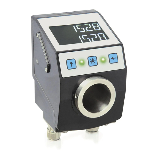
2 Safety information 2.1 Intended use Setpoint display AP10T is used for setpoint visualization e. g. of format adjustments. The setpoint display is only intended for use in industrial applications that are not subject to special electrical or mechanical safety requirements. -
Page 18: Target Group
• are authorized to commission, earth and label circuits and devices/ systems in accordance with the safety standards. 2.4 Basic safety information Danger of explosion DANGER ` Do not use the setpoint display in explosive zones. AP10T · Date 19.05.2016 · Art. No. 88088 · Mod. status 154/16... -
Page 19: Identification
` Using a torque wrench tighten the mating connector(see chapter 7.1, and 7.3). Manufacturer's recommendation of a suitable torque can be obtained on request. Tightening torque: 0.4 Nm AP10T · Date 19.05.2016 · Art. No. 88088 · Mod. status 154/16... -
Page 20: Mechanical Mounting
` Do not disconnect or close live connections. ` Perform wiring work in the de-energized state only. ` Use strands with suitable ferrules. ` Check all lines and plug connections before switching on the device. AP10T · Date 19.05.2016 · Art. No. 88088 · Mod. status 154/16... - Page 21 Faulty or missing termination or level specification results in communica- tion errors and can destroy the displays electronic system. ` Make sure that termination is correct and test it. AP10T · Date 19.05.2016 · Art. No. 88088 · Mod. status 154/16...
- Page 22 For mating connector and cable extension accessories see chapter 7. Designation Bus IN Bus OUT DÜB/CANL DÜA/CANH viewing side = plug-in side AP10T · Date 19.05.2016 · Art. No. 88088 · Mod. status 154/16...
- Page 23 5). Use 6.3 mm flat connectors or cable lug with short strands 2.5 … 4 mm² (not in the scope of delivery). For multiple setpoint displays we recommend connecting the earthing to a ground bar (see Fig. AP10T · Date 19.05.2016 · Art. No. 88088 · Mod. status 154/16...
-
Page 24: Commissioning
A setpoint received is displayed flashing until acknowledged (acknowledg- ment key) and is signified with a red LED. Immediately after acknow- ledgment, the value will be displayed permanently and the relevant green LED will glow. AP10T · Date 19.05.2016 · Art. No. 88088 · Mod. status 154/16... - Page 25 If no key is pressed, the configuration mode will be exited after ~30 s without saving the latest value displayed, i. e. the original value will be maintained. AP10T · Date 19.05.2016 · Art. No. 88088 · Mod. status 154/16...
-
Page 26: Transport, Storage, Maintenance And Disposal
• Do not damage connections through mechanical or thermal impact. • Prior to installation inspect the setpoint display for transport dam- ages. Do not install damaged setpoint displays. AP10T · Date 19.05.2016 · Art. No. 88088 · Mod. status 154/16... -
Page 27: Accessory Connector
. Turn pressure screw to secure the cable. 6. Thread insulating sleeve , solder strands and mount insulating sleeve. 7. Screw coupling sleeve with element and tighten pressure screw AP10T · Date 19.05.2016 · Art. No. 88088 · Mod. status 154/16... -
Page 28: Mating Connector M8 Bus Terminator
2 rows, (backlit ~8 mm height LED red/white) Status display 2x two-color LED (red/green) acknowledgment status, confi- gurable Keys acknowledgment, paramete- rization Bus connection RS485; CANopen no galvanic isolation AP10T · Date 19.05.2016 · Art. No. 88088 · Mod. status 154/16... - Page 29 EN 60529, only with mating con- nector IP65 EN 60529, only with mating con- nector Shock resistance 500 m/s , 11 ms EN 60068-2-27 Vibration resistance 100 m/s , 5 … 150 Hz EN 60068-2-6 AP10T · Date 19.05.2016 · Art. No. 88088 · Mod. status 154/16...
- Page 30 AP10T...
- Page 31 AP10T...
- Page 32 SIKO GmbH Weihermattenweg 2 79256 Buchenbach Telefon/Phone + 49 7661 394-0 Telefax/Fax + 49 7661 394-388 E-Mail info@siko.de Internet www.siko-global.com Service support@siko.de...
Need help?
Do you have a question about the AP10T and is the answer not in the manual?
Questions and answers