Table of Contents
Advertisement
Quick Links
MPCLSVNPEVBUM
MPC-LS Vehicle Network Processing Evaluation Board User
Manual
All information provided in this document is subject to legal disclaimers
Rev. 0 - Feb 2019
1 Introduction
The NXP MPC-LS VNP EVB brings an advanced automotive gateway solution
using NXP's MPC5748G gateway microcontroller and LS1043A
communications processor SoCs. The combination of a real-time
microcontroller with microprocessor application processing enables new
gateway use cases and service-oriented gateways. The complete MPC-LS
VNP EVB solution consists of two boards - a Processor Module and a Platform
Board with a wide array of automotive interfaces.
This document provides detailed reference information for the MPC-LS VNP
Evaluation Board (EVB) comprising a Processor Module and a Platform Board.
This includes detailed board configuration including connectors, jumpers, LED
notifications, board programming, and recovery instructions. The document
also includes usage of software tools and environment for building, flashing,
and debugging the board.
To get familiar with the system, the user needs to follow the below work flow:
1. Bring up the MPC-LS VNP EVB as described in the Quick Start Guide.
(Requires MPC-LS VNP EVB)
2. Install required software per section
3. Build Linux and MPC5748G images as per section
4. Flash images on LS1043A and MPC5748G per section
board or perform board recovery
EVB)
5. Run demo application as per section
References to "DCM" in this manual are legacy references to the MPC-LS EVB Processor Module.
2 Hardware requirements
The table below lists the hardware required:
Table 1. Hardware requirements
Item
MPC-LS VNP EVB
12V, 5A power supply
Micro USB cable
Software
Requirements.
How to
on page 61. (Requires MPC-LS VNP
How to Run
Application. (Requires MPC-LS VNP EVB)
Description
MPC-LS processor board installed on platform board
12V adapter to power the board
For console output from USB to UART port
Table continues on the next page...
Contents
1 Introduction.......................................... 1
2 Hardware requirements.......................1
3 Software requirements........................ 2
5 MPC-LS Platform Board details..........6
6 Debugger connections...................... 11
10 How to run the application.............. 93
A CodeWarrior CCS.............................. 96
Build.
D Revision history.............................. 106
How to flash the
NOTE
LS1043A and MPC5748G................ 15
board recovery................................ 61
VirtualBox........................................ 99
VirtualBox...................................... 102
User's Guide
Advertisement
Table of Contents

Subscribe to Our Youtube Channel
Related Manuals for NXP Semiconductors MPC-LS series


Summary of Contents for NXP Semiconductors MPC-LS series
-
Page 1: Table Of Contents
MPCLSVNPEVBUM MPC-LS Vehicle Network Processing Evaluation Board User Manual All information provided in this document is subject to legal disclaimers Rev. 0 — Feb 2019 User's Guide Contents 1 Introduction 1 Introduction.......... 1 The NXP MPC-LS VNP EVB brings an advanced automotive gateway solution 2 Hardware requirements.......1 using NXP's MPC5748G gateway microcontroller and LS1043A 3 Software requirements...... -
Page 2: Software Requirements
NXP Semiconductors Software requirements Table 1. Hardware requirements (continued) Item Description Ethernet cable Used to flash images to LS1043A via TFTP CWH-CTP-BASE-HE CodeWarrior TAP kit for flashing / debugging LS1043A https://www.nxp.com/support/ developer-resources/software-development-tools/codewarrior-development-tools/run-control- devices/qoriq-ls-processor-probe-tips-for-codewarrior-tap:CWH-CTP-CTX10-YE? tab=Buy_Parametric_Tab#/ CWH-CTP-CTX10-YE CodeWarrior Probe Tip to connect to the LS JTAG connector of MPC-LS processor module. -
Page 3: Mpc-Ls Processor Module Details
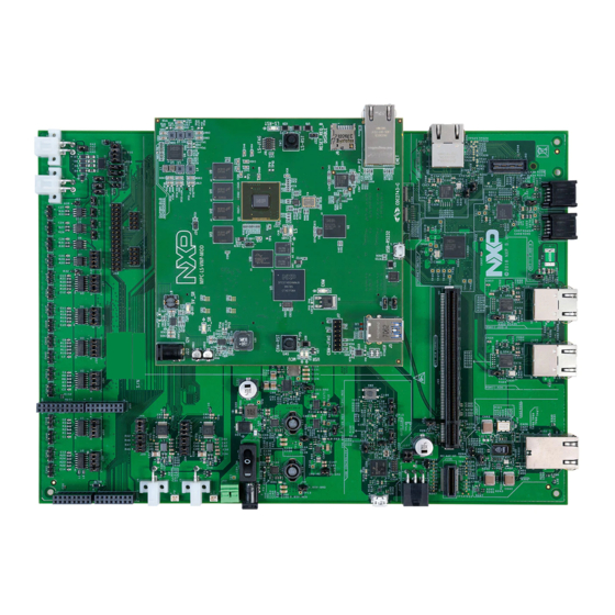
NXP Semiconductors MPC-LS Processor Module details Table 2. Software requirements (continued) Requirement Description Installation details Download Link Click the Downloads TRACE32 for PPC TRACE32 software for http://www.lauterbach.com/frames.html? debugging MPC5748G via button on the left side and home.html Lauterbach. navigate to the TRACE32 software. - Page 4 NXP Semiconductors MPC-LS Processor Module details Power Jack MPC-LS-VNP-MOD LS1043A MPC5748G LS1043A JTAG MPC5748G Reset LS1043A Reset SJA1105S Micro SD Card Slot MPC5748G JTAG Ethernet Port USB Port Micro USB Port Figure 1. MPC-LS Processor Module and its components 4.1 Connector and reset switches The table below describes the MPC-LS Processor module connectors and reset switches: Table 3.
- Page 5 NXP Semiconductors MPC-LS Processor Module details 4.2 Jumpers The table below shows the default jumper settings for the MPC-LS Processor Module: Table 4. MPC-LS Processor Module jumper settings Jumper Size Name/function Description 1x2 pin LS Secure Boot Programming Enable Off: Normal Operation...
-
Page 6: Mpc-Ls Platform Board Details
NXP Semiconductors MPC-LS Platform Board details Table 5. MPC-LS Processor Module LEDs (continued) Color Name Description MPC5748G target reset Reset on JTAG or reset button MPC5748G MCU reset MPC5748G MCU in reset 4.4 Resistor configurations The resistor settings define the boot source of the LS1043A on MPC-LS Processor Module. The default boot source is kept to NOR boot. - Page 7 NXP Semiconductors MPC-LS Platform Board details CAN 4x2 LIN x4 TJA1048T TJA1024HG SPI2CAN breakout connector FlexRay x2 TJA1081 MPC-LS-VNP-MOD MPC-LS Processor Module Platform Board Power Jack MPC5748G micro USB port SJA1105Q RGMII_C RGMII_B SGMII RGMII_A x2 MII x2 5.1 MPC-LS Processor Module connections to the MPC-LS Platform Board...
- Page 8 NXP Semiconductors MPC-LS Platform Board details 2. J2 <-> J66 MPC-LS Vehicle Network Processing Evaluation Board User Manual, Rev. 0, Feb 2019 User's Guide 8 / 107...
- Page 9 NXP Semiconductors MPC-LS Platform Board details Figure 5. J2 to J66 3. J3 <-> J81 Figure 6. J3 to J81 MPC-LS Vehicle Network Processing Evaluation Board User Manual, Rev. 0, Feb 2019 User's Guide 9 / 107...
- Page 10 NXP Semiconductors MPC-LS Platform Board details 4. J4 <-> J87 Figure 7. J4 to J87 MPC-LS Vehicle Network Processing Evaluation Board User Manual, Rev. 0, Feb 2019 User's Guide 10 / 107...
-
Page 11: Debugger Connections
NXP Semiconductors Debugger connections 6 Debugger connections This section shows the hardware connection setup required to connect the debugger of LS1043A and MPC5748G with the MPC- LS VNP EVB. 6.1 CodeWarrior TAP The CodeWarrior TAP allows you to debug and control the LS1043A system on MPC-LS VNP EVB using the CodeWarrior IDE. - Page 12 NXP Semiconductors Debugger connections Figure 8. Cable connections for the CodeWarrior TAP 2. Connect the 10-wire cable to the JTAG headers on MPC-LS Processor Module. When aligned properly, the red stripe will be on Pin 1 toward the inner side of the board.
- Page 13 NXP Semiconductors Debugger connections Pin 1 Figure 9. Connecting the 10-wire cable to JTAG headers on MPC-LS Processor module 3. Connect the mini USB cable from CodeWarrior TAP to UART on PC. The CodeWarrior TAP is now ready to be used.
-
Page 14: Quick Start With Mpc-Ls Vnp Evb
NXP Semiconductors Quick Start with MPC-LS VNP EVB Pin 1 Figure 10. Connecting the 14-wire cable to JTAG header on MPC-LS VNP EVB with Pin 1 7 Quick Start with MPC-LS VNP EVB There are two getting started packages released for MPC-LS VNP EVB: 1. -
Page 15: How To Build The Software For Ls1043A And Mpc5748G
NXP Semiconductors How to build the software for LS1043A and MPC5748G NOTE QSG is related only to the package which is pre-flashed on the board, which is AutoSAR + LSDK. The QSG for Package 1 will be provided later on. - Page 16 NXP Semiconductors How to build the software for LS1043A and MPC5748G 4. Run the installer. 5. Download Ubuntu 18.04. a. Go to https://www.ubuntu.com/desktop/developers b. Click on “Get Ubunto now” box. c. Click on “Download” box for Ubunto 18.0.4.1 LTS. d. The downloaded file is an ISO image. You will need this to mount it on the virtual drive. Steps to do that are explained later in this section.
- Page 17 NXP Semiconductors How to build the software for LS1043A and MPC5748G 9. Allocate RAM of at least 2048 MB. Recommended RAM is 4096 MB if your PC machine has a RAM more than 8 MB. 10. Select create a virtual hard disk now.
- Page 18 NXP Semiconductors How to build the software for LS1043A and MPC5748G 14. The Install Manager will confirm if you need to create the virtual hard disk. Select Create. 15. Select the default directory for the file location. 16. The virtual hard disk will be created.
- Page 19 NXP Semiconductors How to build the software for LS1043A and MPC5748G 18. The Manager will ask to select the startup disk. Provide the Ubuntu 18.04 iso file ‘ubuntu-18.04.1-desktop-amd64.iso’ here that is downloaded in step 5. Click on Start once loaded.
- Page 20 NXP Semiconductors How to build the software for LS1043A and MPC5748G 24. Provide your location and your login credentials. 25. Ubuntu will be installed. 26. If you get the message “Remove Media” , then just hit enter. NOTE All the further instructions and steps mentioned for Linux are common and applicable to both Linux Ubuntu machine as well as Ubuntu on VirtualBox.
- Page 21 NXP Semiconductors How to build the software for LS1043A and MPC5748G Note: Use the command if git is not already installed and sudo apt install git git config --global user.email to set your account’s default identity. “you@email.com”” >>cd .. 5. For the U-Boot and linux images, follow the below steps in DCM_git directory: U-Boot: “git clone https://github.com/qoriq-open-source/u-boot”...
- Page 22 NXP Semiconductors How to build the software for LS1043A and MPC5748G 8.1.3.2 Ubuntu build tool chain On your Ubuntu machine, run the following set of commands to download the linaro tool chain and set the cross compiler before building the source code.
- Page 23 NXP Semiconductors How to build the software for LS1043A and MPC5748G The patches need to be downloaded one at a time. For example: 1. Click on the first patch to be downloaded: 2. Patch text file opens. Right-click anywhere in file and select Save Page As….
- Page 24 NXP Semiconductors How to build the software for LS1043A and MPC5748G The patch will be applied to directory. NOTE If there are errors while applying the patches, the user can run the command “sudo git am -abort” in the u-boot, linux, and rcw directories.
- Page 25 NXP Semiconductors How to build the software for LS1043A and MPC5748G 10. For adding the linux patch, use: >cd ../linux >sudo git am ../dcm-linux_patches_addons/* 8.1.3.4 Build RCW Use the steps described in this section to build RCW. 1. Run the below commands to build the image for rcw:...
- Page 26 NXP Semiconductors How to build the software for LS1043A and MPC5748G 8.1.3.5 Building U-Boot Follow these steps for building U-Boot specifically for a defined boot source. 1. Before building, create a directory inside . Create four subdirectories inside it: u-boot_binary /DCM_git/ •...
- Page 27 NXP Semiconductors How to build the software for LS1043A and MPC5748G 3. Copy the binary to /DCM_git/u-boot_binary/ddr/ and rename it to “u-boot-dtb_ramboot.bin” . NOTE The U-Boot binary in the /DCM_git/u-boot directory will be replaced by the binary of the latest U-Boot build i.e after the instructions to build QSPI NOR U-Boot are passed, the U-Boot binary for DDR is overwritten.
- Page 28 NXP Semiconductors How to build the software for LS1043A and MPC5748G 2. In the same directory, the file “u-boot-with-spl-pbl.bin” is the U-Boot created for NAND. 3. Copy the binary to /DCM_git/u-boot_binary/nand and rename it to “u-boot-with-spl-pbl-nand.bin” . 8.1.3.5.4 SD boot 1.
- Page 29 NXP Semiconductors How to build the software for LS1043A and MPC5748G 2. In the same directory, the file “u-boot-with-spl-pbl.bin” is the U-Boot created for sd memory. 3. Copy the binary /DCM_git/u-boot_binary/sd and rename it to “u-boot-with-spl-pbl_sd.bin” . 8.1.3.6 Build Linux Run the following set of command to build the Linux image.
- Page 30 NXP Semiconductors How to build the software for LS1043A and MPC5748G 4. Go to the webpage https://packages.debian.org/jessie/tcpdump and download “libpcap0.8” and “libssl1.0.0” for arm64 architecture. “libpcap0.8_1.6.2-2_arm64.deb” and “libssl1.0.0_1.0.1t-1+deb8u7_arm64.deb” files will be downloaded. Download from the North America server as highlighted below: MPC-LS Vehicle Network Processing Evaluation Board User Manual, Rev.
- Page 31 NXP Semiconductors How to build the software for LS1043A and MPC5748G 5. Create directory “libpcap” and “libssl” in “ramdisk_fs” . 6. Move “libpcap0.8_1.6.2-2_arm64.deb” file to “libpcap” and “libssl1.0.0_1.0.1t-1+deb8u7_arm64.deb” file to “libssl” directory. 7. Go to “libpcap” directory and pass the command “dpkg -x libpcap0.8_1.6.2-2_arm64.deb .” . “usr” folder will be created.
- Page 32 NXP Semiconductors How to build the software for LS1043A and MPC5748G 12. Pass the command below in the /DCM_git/linux directory. mv ramdisk_rootfs_arm64.ext4.gz fsl-image-core-ls1043ardb.ext2.gz 13. Change directory to /DCM_git/linux. Then, run the following commands: >>export ARCH=arm64 >>export CROSS_COMPILE=aarch64-linux-gnu- >>export PATH=$PATH:/home/<user>/DCM_git/gcc-linaro-6.3.1-2017.05-x86_64_aarch64-linux-gnu/bin 14. Run the command: >>make defconfig...
- Page 33 NXP Semiconductors How to build the software for LS1043A and MPC5748G 17. Run the command: >>../u-boot/tools/mkimage -f kernel-ls1043a-rdb.its kernel-ls1043a-rdb.itb MPC-LS Vehicle Network Processing Evaluation Board User Manual, Rev. 0, Feb 2019 User's Guide 33 / 107...
- Page 34 NXP Semiconductors How to build the software for LS1043A and MPC5748G After successful build, the bin “kernel-ls1043a-rdb.itb” will be created at “ . ./DCM_git/linux/” . After all the images are built, follow the section LS1043A to learn how to flash the images on MPC-LS VNP EVB.
- Page 35 NXP Semiconductors How to build the software for LS1043A and MPC5748G 5. Pass the command for cleaning all the existing object files. make clean 6. Run in the same directory to build. An elf will be created in directory. To add the elf...
- Page 36 NXP Semiconductors How to build the software for LS1043A and MPC5748G 4. Run the below command to set the cross compile path: >>export CROSS_COMPILE=/home/<user>/DCM_git/gcc-linaro-6.3.1-2017.05-x86_64_aarch64-linux- gnu/bin/aarch64-linux-gnu- 5. Pass the command for cleaning all the existing object files. make clean 6. Run in the same directory to build.
- Page 37 NXP Semiconductors How to build the software for LS1043A and MPC5748G d. Save the file and exit. For this the user need to press Esc, type “:” and then “wq” . Press Enter. e. >sudo umount TEMP/ f. >sudo gzip -9 fsl-image-core-ls1043ardb.ext2 5.
- Page 38 NXP Semiconductors How to build the software for LS1043A and MPC5748G The executable will be placed in as Linux is booted on MPC-LS VNP EVB. ls_ipcf_tx_rx /home/root 8.2 MPC5748G Bare-metal build example ® Install S32 Design Studio for Power Architecture 2017.R1 - Windows/Linux(REV 2017.R1) from...
- Page 39 NXP Semiconductors How to build the software for LS1043A and MPC5748G d. Go to General -> Existing Projects into workspace e. Click on Browse and select the MPC5748G S32DS project source code and click on Finish. f. The project has been loaded into S32DS workspace.
- Page 40 NXP Semiconductors How to build the software for LS1043A and MPC5748G 3. Check if any errors/warnings are generated in the code from the Problems tab(Alt + Shift + Q, then press X). 4. In the Project Explorer, you can see the binary created as shown in the snapshot. Right-click on the binary and select properties, select the directory where it is placed.
- Page 41 NXP Semiconductors How to build the software for LS1043A and MPC5748G 8.3 MPC5748G AUTOSAR build NOTE NXP has integrated its IPCF communication framework into ARCCORE’s AUTOSAR stack on MPC-LS VNP EVB under evaluation license from ARCCORE https://www.arccore.com/. This section provides step by step build guide for ARCCORE's AUTOSAR and IPCF integration. As a pre-requisite for this section, please contact ARCCORE directly for AUTOSAR stack and Arctic Studio licenses.
- Page 42 NXP Semiconductors How to build the software for LS1043A and MPC5748G 3. Right-click in the AUTOSAR Navigator window and select import. MPC-LS Vehicle Network Processing Evaluation Board User Manual, Rev. 0, Feb 2019 User's Guide 42 / 107...
- Page 43 NXP Semiconductors How to build the software for LS1043A and MPC5748G 4. Select “General” and “Existing Projects into Workspace” and click on Next. MPC-LS Vehicle Network Processing Evaluation Board User Manual, Rev. 0, Feb 2019 User's Guide 43 / 107...
- Page 44 NXP Semiconductors How to build the software for LS1043A and MPC5748G 5. Click Browse, and select the “core” folder in the project and select OK. MPC-LS Vehicle Network Processing Evaluation Board User Manual, Rev. 0, Feb 2019 User's Guide 44 / 107...
- Page 45 NXP Semiconductors How to build the software for LS1043A and MPC5748G 6. Click “Finish” . 7. The model files will be loaded automatically as the “core” is imported. MPC-LS Vehicle Network Processing Evaluation Board User Manual, Rev. 0, Feb 2019...
- Page 46 NXP Semiconductors How to build the software for LS1043A and MPC5748G 8. Right-click again in the AUTOSAR navigator window and select import. 9. Select General -> Existing projects into workspace->Next->Browse and select the Ethernet simple project available inside Ethernet Simple example folder as shown in the snapshot.
- Page 47 NXP Semiconductors How to build the software for LS1043A and MPC5748G 10. Click OK and then Finish. 11. Expand “Ethernet Simple” in the AUTOSAR navigator window and double click on the “EthernetSimple_mpc5748g_mpc574xg_mb_Configuration.arxml” . The “EthernetSimple_mpc5748g_mpc574xg_mb_Ecu – BSW Editor” will open as shown in the snapshot below.
- Page 48 NXP Semiconductors How to build the software for LS1043A and MPC5748G 12. Double-click on TcpIp module. 13. Expand the “TcpIpConfig” and check if the following subcontainers as shown in the snapshot below are present or not. If already present skip to step 18.
- Page 49 NXP Semiconductors How to build the software for LS1043A and MPC5748G 14. In the TcpIp, add TcpIpConfig. Right-click on “TcpIpConfig” and choose “Create TcpIpLocalAddr” 15. Right-click on “TcpIpConfig” again, select “Create TcpIpCtrl” . MPC-LS Vehicle Network Processing Evaluation Board User Manual, Rev. 0, Feb 2019...
- Page 50 NXP Semiconductors How to build the software for LS1043A and MPC5748G 16. Right-click on “TcpIpConfig” again, select “Create TcpIpIpConfig” . 17. Right-click on “TcpIpConfig” again, select “Create TcpIpSocketOwnerConfig” . 18. Right-click on “TcpIpSocketOwnerConfig” , create a new TcpIpSocketOwner with name “Ipcf” . See the below snapshot for reference to set the general settings for this socket owner.
- Page 51 NXP Semiconductors How to build the software for LS1043A and MPC5748G 20. Double-click on the EthIf Module highlighted below. 21. Under “EthIfConfigSet” , go to “EthIfController” and click the “Select reference value” button on the right side of “Eth If Eth Ctrl Ref”...
- Page 52 NXP Semiconductors How to build the software for LS1043A and MPC5748G 22. Select “EthCtrlConfig” under Eth->EthConfigSet as highlighted in the snapshot below and click on OK. 23. Save the configurations using Ctrl+s and click the red cross on the top right side to close the configurations for EthIf module.
- Page 53 NXP Semiconductors How to build the software for LS1043A and MPC5748G 25. Go to EcuM->EcuMCommonConfiguration->EcumSleepMode and click the “select reference value” button for “Ecu MSleep Mode Mcu Mode Ref” as highlighted in the snapshot below. 26. Select SLEEP for the mpc5748g board as highlighted in the snapshot below and click on OK.
- Page 54 NXP Semiconductors How to build the software for LS1043A and MPC5748G 27. Go to EcuM->EcuMConfiguration->EcuMFixedConfiguration click the “select reference value” button for “Ecu MNormal Mcu Mode Ref” as highlighted in the snapshot below. MPC-LS Vehicle Network Processing Evaluation Board User Manual, Rev. 0, Feb 2019...
- Page 55 NXP Semiconductors How to build the software for LS1043A and MPC5748G 28. Select RUN for the mpc5748g board as highlighted in the snapshot below and click on OK. MPC-LS Vehicle Network Processing Evaluation Board User Manual, Rev. 0, Feb 2019...
- Page 56 NXP Semiconductors How to build the software for LS1043A and MPC5748G 29. Save the configurations using Ctrl+s and click the red cross on the top right side to close the configurations for EcuM module. 30. Double-click the OS module highlighted below to update it.
- Page 57 NXP Semiconductors How to build the software for LS1043A and MPC5748G 33. Click OsApplication and add a new Os App Task Ref by clicking on the ‘+’ icon highlighted in the snapshot below. 34. Click the “select reference value” button for this Os App Task Ref and select udp_mcapi_demo_task and click on OK.
- Page 58 NXP Semiconductors How to build the software for LS1043A and MPC5748G 35. Save the configurations using Ctrl+s and click the red cross on the top right side to close the configurations for Os module. 36. Click Generate symbol on the top right side encircled in the snapshot below.
- Page 59 NXP Semiconductors How to build the software for LS1043A and MPC5748G 37. The console window will show the log of generation. Once the generation is completed a log message displaying “INFO : Generation complete” will be displayed on the Console window.
- Page 60 NXP Semiconductors How to build the software for LS1043A and MPC5748G 1. The “apps” folder is contained outside the core directory for your application. 2. A source folder “cal_ipcf_rx_tx” is inside the apps folder. A folder named “src” will be inside “cal_ipcf_rx” folder. The “src”...
-
Page 61: How To Flash The Board Or Perform Board Recovery
NXP Semiconductors How to flash the board or perform board recovery 4. The build.sh file helps to build the whole AUTOSAR OS along with application written on it into a single executable file. To obtain the executable, write “ . /build.sh clean” and then “ . /build.sh all” on the msys terminal in the present working directory. - Page 62 NXP Semiconductors How to flash the board or perform board recovery 4. Select the cmm script file provided along with this release. mpc574xg.cmm 5. Program flash memory confirmation dialog will open, click Yes. 6. Select the enet_rmii_udp_Z4_1.elf executable file provided along with the release and click on Open.
- Page 63 NXP Semiconductors How to flash the board or perform board recovery 7. Now click on “GO icon” to run the executable file on MPC5748G. 8. In case of Package 1, the DS3 LED of MPC5748G will turn on indicating it is working. The executable file on MPC5748G runs a diagnostic test, testing UART2USB connection, SPI initialization, SJA1105S switch’s valid configuration, and the...
- Page 64 NXP Semiconductors How to flash the board or perform board recovery Figure 12. Downloading Codewarrior Development Suites 3. Select the latest version of CodeWarrior for QorIQ LS Series ARMv8 ISA. Evaluation / Updates as shown in the preceding figure. NOTE The version available on the URL might be different from the one shown in the snapshot.
- Page 65 NXP Semiconductors How to flash the board or perform board recovery 5. Now, select the files as shown in the snapshot and click Download Selected Files. NOTE The files might be displayed in a different order than as shown in the figure below.
- Page 66 NXP Semiconductors How to flash the board or perform board recovery 6. Let the download complete. 7. After the download is completed go to the directory where the file has been saved and install CodeWarrior Networked Applications Windows Hosted-Offline v2017.03.exe as shown in the snapshot below.
- Page 67 NXP Semiconductors How to flash the board or perform board recovery 9. Agree to the Linaro License Agreement by clicking I Agree as shown in the snapshot below. MPC-LS Vehicle Network Processing Evaluation Board User Manual, Rev. 0, Feb 2019...
- Page 68 NXP Semiconductors How to flash the board or perform board recovery 10. In the Choose Components windows, choose the default files as shown in the snapshot below. MPC-LS Vehicle Network Processing Evaluation Board User Manual, Rev. 0, Feb 2019 User's Guide...
- Page 69 NXP Semiconductors How to flash the board or perform board recovery 11. A temporary license file for 15 days will be generated. One can register with NXP to receive a permanent license. MPC-LS Vehicle Network Processing Evaluation Board User Manual, Rev. 0, Feb 2019...
- Page 70 NXP Semiconductors How to flash the board or perform board recovery 12. After the installation completes, launch the CW IDE. Option 1: “C:\Freescale\CW4NET_v2017.03\CW_ARMv8” and open “fsl_eclipse.bat” . Option 2: Search from the Windows Start menu, CodeWarrior for Armv8. 13. Create a workspace as shown below MPC-LS Vehicle Network Processing Evaluation Board User Manual, Rev.
- Page 71 NXP Semiconductors How to flash the board or perform board recovery 14. Close the Welcome window. 15. Now click on the Open Perspective window option on the top right part of the screen, then select Debug and click OK. MPC-LS Vehicle Network Processing Evaluation Board User Manual, Rev. 0, Feb 2019...
- Page 72 NXP Semiconductors How to flash the board or perform board recovery 16. Click on Target Connections, find LS1043A_RDB board, right-click on it and click on “Duplicate” . Why duplicate: Because the predefined configurations for evaluation systems • Cannot be deleted •...
- Page 73 NXP Semiconductors How to flash the board or perform board recovery 17. Give a new name to the board and click on OK. The new board will now come at the top of the board list. Figure 16. Target Connections window 18.
- Page 74 NXP Semiconductors How to flash the board or perform board recovery 9.2.1.2 CodeWarrior TAP connection Connect the mini USB cable from CodeWarrior TAP to your windows machine. Also connect the JTAG connector of CodeWarrior on J16 JTAG of MPC-LS-VNP-EVB as described in Section CodeWarrior TAP.
- Page 75 NXP Semiconductors How to flash the board or perform board recovery NOTE In cases where network diagnostics problem is faced, follow the steps mentioned in CodeWarrior CCS on page 9.2.1.4 Flashing U-Boot in LS1043A In this section, the U-Boot image is loaded into the DRAM section.
- Page 76 NXP Semiconductors How to flash the board or perform board recovery 2. In the Target Init File tab, delete the text and paste the TargetInit.txt file contents.TargetInit.txt is provided along with the package. Perform this activity twice to reflect the change in the file.
- Page 77 NXP Semiconductors How to flash the board or perform board recovery Figure 22. Closing the Target Configuration Window 4. Click on Connect (see arrow below). 5. Go to Window -> Show View -> Memory. MPC-LS Vehicle Network Processing Evaluation Board User Manual, Rev. 0, Feb 2019...
- Page 78 NXP Semiconductors How to flash the board or perform board recovery 6. Go to the Memory tab, click the green plus sign, enter the address as 0x82000000, and press OK. MPC-LS Vehicle Network Processing Evaluation Board User Manual, Rev. 0, Feb 2019...
- Page 79 NXP Semiconductors How to flash the board or perform board recovery 7. Go to 0x82000000 address and select HEX view. Note: If the view is already hex, continue with the next step. 8. Click Import. MPC-LS Vehicle Network Processing Evaluation Board User Manual, Rev. 0, Feb 2019...
- Page 80 NXP Semiconductors How to flash the board or perform board recovery 9. Select the Format as Raw Binary, check the address is 0x82000000, and load the u-boot-dtb_ramboot.bin file and Press OK. The memory address provided is a part of the DRAM section. Note: The user has already built this image in boot.
- Page 81 NXP Semiconductors How to flash the board or perform board recovery 11. Execute Tera Term. 12. Select the serial option in Tera Term and ensure that USB serial port is selected and click OK. 13. Select Setup > Serial port.
- Page 82 NXP Semiconductors How to flash the board or perform board recovery 14. Configure the serial port of the host machine with the following settings: • Baud Rate:115200 bits/s • Number of data bits: 8 • Parity : None • Number of stop bits: 1 •...
- Page 83 NXP Semiconductors How to flash the board or perform board recovery The board boots up and the console shows the U-Boot messages as shown in the image below. To reach U-Boot prompt, press any key to stop autoboot. 9.2.1.5 Flashing images from U-Boot console via serial port The user has two available options to flash the images on MPC-LS-VNP-EVB.
- Page 84 NXP Semiconductors How to flash the board or perform board recovery NOTE If you have flashed binaries of Getting Started package 2 on the MPC5748G side, set the speed of the Ethernet port to 100 Mbps Full Duplex in the Ethernet adapters. To do so, go to Network and Sharing Center -> Change adapter settings.
- Page 85 NXP Semiconductors How to flash the board or perform board recovery 4. Select the “u-boot-dtb_qspi.bin” file and click on “Open” . This is the U-Boot image for NOR memory. 5. Let the transfer complete. 6. Once the transfer completes, write the following commands on Tera Term console: sf erase 0x100000 0x100000 Press enter.
- Page 86 NXP Semiconductors How to flash the board or perform board recovery Press enter. Then, run the command: sf write 0x90000000 0x0 0x100000 9. Now again type “loady” on the console, press enter, go to File -> Transfer -> YMODEM -> send and select the “ppa.itb”...
- Page 87 NXP Semiconductors How to flash the board or perform board recovery 9.2.1.6 Flashing images from U-Boot console via MPC-LS Processor Module ethernet port 1. Connect the MPC-LS Processor Module ethernet port to your PC using an Ethernet cable. 2. Assign “192.168.1.1” as the IP address to your PC by going in the Network and Sharing Center. Go to Change adapter settings.
- Page 88 NXP Semiconductors How to flash the board or perform board recovery 5. Enter these commands at the U-Boot prompt to enable Ethernet. setenv ethact FM1@DTSEC9 setenv ethaddr 00:04:9F:03:D9:D7 setenv eth1addr 00:04:9F:03:D9:D8 setenv eth2addr 00:04:9F:03:D9:D9 setenv eth3addr 00:04:9F:03:D9:DA setenv eth4addr 00:04:9F:03:D9:DB...
- Page 89 NXP Semiconductors How to flash the board or perform board recovery NOTE Save your settings to flash using the saveenv command so that it can be used after reboot. Use the edit command to edit any Environment variable when it is already present, else use setenv for first time.
- Page 90 NXP Semiconductors How to flash the board or perform board recovery 8. Execute the below commands to flash the images: a. RCW tftp 0x90000000 rcw_1600_qspiboot_swapped.bin sf probe sf erase 0x0 0x100000 sf write 0x90000000 0x0 0x100000 b. U-Boot tftp 0x90000000 u-boot-dtb_qspi.bin...
- Page 91 NXP Semiconductors How to flash the board or perform board recovery sf erase 0x400000 0x100000 sf write 0x90000000 0x400000 0x100000 d. Fman tftp 0x90000000 fsl_fman_ucode_ls1043_r1.1_106_4_18.bin sf probe sf erase 0x900000 0x100000 sf write 0x90000000 0x900000 0x100000 e. Linux tftp 0xa0000000 kernel-ls1043a-rdb.itb...
- Page 92 NXP Semiconductors How to flash the board or perform board recovery 11. The Linux shell will ask for login, enter and press Enter. The Linux shell is up. root 9.2.2 Using SD boot 9.2.2.1 Hardware settings For SD boot, follow the hardware settings as mentioned in...
-
Page 93: How To Run The Application
NXP Semiconductors How to run the application 4. Linux: kernel-ls1043a-rdb.itb sudo dd if=kernel-ls1043a-rdb.itb of=/dev/sde bs=512 seek=32768 Put the SD card into the micro SD card slot and power on MPC-LS VNP EVB to view the U-Boot and Linux console. 10 How to run the application This section describes the steps for running the applications of both the getting started packages on LS1043A and MPC5748G. - Page 94 NXP Semiconductors How to run the application If the user wants to run the application again, follow the below step: 1. ./ls_ipcf_tx_rx <command> <command> accepts the following parameters as input: • get_status : LS1043A seeks status from MPC5748G, waits for response and MPC5748G responds with the status of switch initialization, spi initialization, tcpip initialization and successful LS1043A out of reset.
- Page 95 NXP Semiconductors How to run the application • led_on: • led_off: MPC-LS Vehicle Network Processing Evaluation Board User Manual, Rev. 0, Feb 2019 User's Guide 95 / 107...
-
Page 96: A Codewarrior Ccs
NXP Semiconductors CodeWarrior CCS 10.2 MPC5748G The application runs as soon as the executable file is flashed to it for both bare-metal and AUTOSAR software (i.e. for both package 1 and package 2). In the case of bare-metal software, MPC5748G sends UDP packets to LS1043A continuously. - Page 97 NXP Semiconductors CodeWarrior CCS 2. In the Target Connection Configurator window that opens, click the USB button if not already selected. Step 3: 1. The CodeWarrior tools communicate with the TAP run controllers through a CodeWarrior Connection. 2. The CodeWarrior connection server console can be used to cross-check if the CodeWarrior TAP is connected during a task like “inspect”...
- Page 98 NXP Semiconductors CodeWarrior CCS 4. Write “show cc” to see the CodeWarrior TAP connected. 5. Configure the CodeWarrior TAP by deleting the previous configurations, configure it again for the USB port it is connected to by executing the commands as shown in the snapshot.
-
Page 99: B Running 64-Bit Guest On Virtualbox
NXP Semiconductors Running 64-bit guest on VirtualBox 6. After the above commands, the user needs to run the below commands: >>>ccs::config_chain {ls1043a dap sap2} >>display ccs::get_config_chain CC console log that will be displayed is: • CodeWarrior TAP executable differs from local file. - Page 100 NXP Semiconductors Running 64-bit guest on VirtualBox i. Restart your laptop, press and hold "F2" on the computer keyboard when the Dell logo appears on the screen. The computer will enter the system setup program to display information stored in BIOS.
- Page 101 NXP Semiconductors Running 64-bit guest on VirtualBox b. Select Do not restart. 4. Delete the related EFI variables. a. Run CMD as administrator. MPC-LS Vehicle Network Processing Evaluation Board User Manual, Rev. 0, Feb 2019 User's Guide 101 / 107...
-
Page 102: C Enable Copy And Paste From/To Virtualbox
NXP Semiconductors Enable copy and paste from/to VirtualBox b. Run below commands (Ensure B is an unused drive, else change to another drive): i. mountvol B: /s ii. copy %WINDIR%\System32\SecConfig.efi B:\EFI\Microsoft\Boot\SecConfig.efi /Y iii. bcdedit /create {0cb3b571-2f2e-4343-a879-d86a476d7215} /d "DebugTool" /application osloader iv. - Page 103 NXP Semiconductors Enable copy and paste from/to VirtualBox 2. Select Devices – Drag and Drop - Bidirectional 3. Exit (Power off the machine) 4. Restart machine and see that copy and paste works now. a. Install guest addition. If copy and paste still does not work, download and install guest addition. This applies whether running on a Windows or Linux machine.
- Page 104 NXP Semiconductors Enable copy and paste from/to VirtualBox 5. In VM VirtualBox Manager, click on Settings – Storage 6. Click icon to add optical drive: 7. Click on Choose Disk and navigate to the downloaded ISO image: MPC-LS Vehicle Network Processing Evaluation Board User Manual, Rev. 0, Feb 2019...
- Page 105 NXP Semiconductors Enable copy and paste from/to VirtualBox 8. Example after .ISO file selected: 9. Click OK. 10. Restart image. LINUX MACHINE GUEST ADDITION STEPS: 1. Log in to Ubuntu. 2. Select Devices – Insert Guest Additions CD image… MPC-LS Vehicle Network Processing Evaluation Board User Manual, Rev. 0, Feb 2019...
-
Page 106: D Revision History
NXP Semiconductors Revision history 3. Navigate to downloaded .iso file and click OK 4. Exit and restart. 5. Now the user can continue with the steps as mentioned in the section Source Path. NOTE The copy and paste in Windows requires using right mouse click – COPY and right mouse click – PASTE instead of Windows Ctrl-C and Ctrl-V. - Page 107 How To Reach Us Information in this document is provided solely to enable system and software implementers to use NXP products. There are no express or implied copyright licenses granted hereunder to Home Page: design or fabricate any integrated circuits based on the information in this document. NXP nxp.com reserves the right to make changes without further notice to any products herein.
Need help?
Do you have a question about the MPC-LS series and is the answer not in the manual?
Questions and answers