Advertisement
Table of Contents
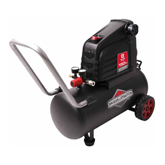
8 GAL PORTABLE
OIL FREE AIR COMPRESSOR
Read and understand this operator's manual thoroughly before using the product. It contains important
information for your safety as well as operating and maintenance advice.
BRIGGS & STRATTON CORPORATION,
MILWAUKEE, WISCONSIN, U.S.A.
Product Model # 074025-00
Manual # 80018805
Advertisement
Table of Contents

Related Manuals for Briggs & Stratton 074025-00


Summary of Contents for Briggs & Stratton 074025-00
- Page 1 8 GAL PORTABLE OIL FREE AIR COMPRESSOR Product Model # 074025-00 Manual # 80018805 Read and understand this operator's manual thoroughly before using the product. It contains important information for your safety as well as operating and maintenance advice. BRIGGS & STRATTON CORPORATION,...
- Page 2 Thank you for purchasing this quality-built Briggs & Stratton ™ air compressor. We are pleased that Briggs & Stratton brand. When operated and maintained according to the instructions in this manual, your Briggs &Stratton air compressor will provide many years of dependable service. You can contact Briggs &...
-
Page 3: Product Registration Form
CONGRATULATIONS ON YOUR NEW PRODUCT PURCHASE! Thank you for choosing a product from the Briggs & Stratton family of brands. We are honored that you chose us as your power equipment provider. WE STRIVE TO CREATE HELPFUL, DEPENDABLE PRODUCTS THAT YOU CAN RELY ON FOR YEARS TO COME, WHILE COUNTING ON US TO SUPPORT YOU THROUGH THE LIFE OF YOUR PRODUCT. -
Page 4: Table Of Contents
Table of Contents Product Registration Form....................Safety Guidelines........................Key Parts Diagram......................... Parts Description........................Assembly Instructions............................. 9 Operating Instructions......................Care and Maintenance......................Troubleshooting........................Warranty..........................Technical Specifications......................Exploded View........................Parts List..........................SAVE THESE INSTRUCTIONS This manual contains important safety and operating instructions. Read all instructions and follow them with use of this product. -
Page 5: Safety Guidelines
Safety Guidelines Important Safety Information The manufacturer cannot possibly anticipate every possible circumstance that might involve a hazard. The warnings work method, or operating technique that the manufacturer does not specifically recommend, you must satisfy yourself that it is safe for you and others. You must also make sure that the procedure, work method, or operating technique that you choose does not render the compressor unsafe. - Page 6 Safety Information DO NOT OPERATE THIS UNIT UNTIL YOU READ AND UNDERSTAND THIS INSTRUCTION MANUAL FOR SAFETY, OPERATION, AND MAINTENANCE INSTRUCTIONS. WARNING compressor. High pressure air could result in death or serious injury. Never operate above maximum operating pressure of the spray gun or tool. Drain water from tank after each use. Do not weld or repair tank.
-
Page 7: Key Parts Diagram
Key Parts Diagram Electric Motor & Air Compressor Pump Pressure Relief Valve Air Tank ON/OFF Switch Tank Pressure Gauge Power Cord Air Pressure Regulator Handle Regulated Pressure Gauge Wheel Air Line Outlet Air Filter Air Tank Ball Valve... -
Page 8: Parts Description
Parts Description A. ELECTRIC MOTOR: The motor is used to power the pump. It contains a thermal overload protector. If the motor overheats for any reason, the thermal overload protector will shut it down in order to prevent the motor from being damaged. AIR COMPRESSOR PUMP: The pump is used to compress the air and discharge it into the tank via the piston moving up and down in the cylinder. -
Page 9: Assembly Instructions
Assembly Instructions PREPARATION Before beginning assembly of product, make sure all parts are present. Compare parts with package contents list and hardware contents list. If any part is missing or damaged, do not attempt to assemble the product. Estimated Assembly Time: 5 minutes Tools Required for Assembly (not included): 11/16 in. -
Page 10: Operating Instructions
Operating Instructions BEFORE EACH START UP 1. Set the ON/OFF switch (I) to the O (off) position. 2. Turn the air pressure regulator knob (D) counterclockwise until it stops. 3. Attach air hose/accessories or air tools (not included) to the air line outlet (F). WARNING! Risk of bursting. -
Page 11: Care And Maintenance
Care and Maintenance WARNING: To avoid personal injury, always shut off and unplug the unit and relieve all air pressure from the system before performing. Regular maintenance will ensure trouble-free operation. SERVICE TASK DESCRIPTION INTERVAL To prevent corrosion inside the tank, the condensation must be drained at the end of every workday. -
Page 12: Troubleshooting
Troubleshooting PROBLEM POSSIBLE CAUSE CORRECTIVE ACTION 1. The tank ball valve is open. 1. Close the ball valve. 2. There is a leak in the fittings. 2. Check fittings with soapy water. Tighten or reseal leaking fittings. DO NOT OVERTINGHTRN. 3. - Page 13 Troubleshooting PROBLEM POSSIBLE CAUSE CORRECTIVE ACTION 1. Tank pressure exceeds the preset 1. The motor will start automatically when pressure switch limit. the tank pressure drops below the tank 2. The fuse is blown or the circuit breaker cut-in pressure. tripped.
-
Page 14: Warranty
Briggs & Stratton Air Compressor Warranty Policy October, 2015 LIMITED WARRANTY BRIGGS & STRATTON is a trademark of BRIGGS & STRATTON CORPORATION and is used under license to Alton Industry Co. Ltd®. Alton Industry Co. Ltd warrants this Briggs & Stratton brand product for a period of one year from the date of original retail purchase against defects in materials and workmanship. -
Page 15: Technical Specifications
Product Specifications Model No. 074025-00 / 0300841 Pump Oil free, Direct drive, Single stage Motor 1.5 HP Voltage/Amps/HZ 120/12/60 Air Tank Capacity 8 Gallon Cut-in Pressure 120 PSI Cut-out Pressure 150 PSI CFM @ 40 PSI CFM @ 90 PSI Power Cord SJT 16 AWG / 72 in. -
Page 16: Exploded View
Exploded View BRIGGSandSTRATTON.COM... -
Page 17: Parts List
Parts List PART DESCRIPTION PART DESCRIPTION Rubber foot Air filter Bolt M10 X 20 Back shroud Anchor nut Self-tapping screw ST3.9 X16F Power cord Bolt M5 X 12 Thumbscrew Bolt M8 X 25 Check valve Tranfer tube Quick coupler Washer Ø8 Regulator Cushion pad Relief valve...
Need help?
Do you have a question about the 074025-00 and is the answer not in the manual?
Questions and answers