
Subscribe to Our Youtube Channel
Related Manuals for Briggs & Stratton Brute 074005


Summary of Contents for Briggs & Stratton Brute 074005
- Page 1 r Compressor rator's BRIGGS& STRATTON POWERPRODUCTS GROUP,LLC JEFFERSON, W ISCONSIN,U.S.A. Manual No. 206934GS Revision - (03/13/2008)
- Page 2 Thankyon for purchasing this quality-built Briggs & Stratton air compressor. We are pleased that you've placed your confidence in the BRUTE brand. When operated and maintained according to the instructions in this manual, your Briggs & Stratton air compressor will provide many years of dependable service. This manual containssafety information to make you aware of the hazards and risks associated with air compressors and how to avoid them.
-
Page 3: Table Of Contents
Table of Contents OperatorSafety ......... Equipment Description......... Safety Rules..........Assembly ........Air Compressor Assembly ........Air Tool Assembly ..........Featuresand Controls......Air Compressor ..........Air Tools........... Operation ........Air Compressor Operating Location......Grounding Instructions ........Extension Cords..........Break-In Procedure .......... Starting Your Air Compressor ........ -
Page 4: Operatorsafety
Operator Safety Safety Rules EquipmentDescription This is the safety alert symbol. It is usedto alert you to potential personal injury hazards.Obey all safety messagesthat follow this symbolto avoid possibleinjury or death. Read this manual carefully and becomefamiliar with your air compressor.Knowits applications, its The safety alert symbol (,_.) is used with a signal word limitations and any hazards involved. - Page 5 WARNING WARNING Hidden internal tank corrosion can cause violent Failure to read and follow instructions explosion leading to severe injury and / or bodily Operator's Manual result in death, property damage. injury and / or property damage. • Before using this product, read this Operator's Manualand Exceeding pressure rating of attachments or inflatables can cause severe injury and / or follow all Safety Rules and Operating Instructions listed.
- Page 6 NOT/ WARNING Compressed air is not breathableand can cause Serious damage may result if the break-in instructions bodily injury. not closely followed. • This procedure is required before the air compressor is put into Some paints or solvents may be harmful if service and when the CheckValve or a compbte compressor inhaled or ingested, causing severe nausea, pump has been repbced.
-
Page 7: Assembly
ASSe[[IbJy 3. Slide a M8 flat washer (A) over a M8-1.25 x 30 bolt (B). Air Compressor A ssembly UnpackAir Compressor 1. Remove accessories and packing from carton. 2. Open carton completely by cutting each corner from top to bottom. 3. - Page 8 Install Air Filter Remove and discard shipping plug. 1. Remove shipping cap (A) and install air filter stem (B). Using oil funnel, slowly add provided oil into oil fill (!(). Tighten by hand. Visually inspect oil level frequently at sight glass (L) to avoid overfilling air compressor pump.
- Page 9 Air Hose Air ToolAssernbly Use a 10 ft. (3 m) or 25 ft. (7.5 m) (supplied) air hose, The air tools need some assembly and lubrication before first minimum 1/4" (6.35 mm) inside diameter (i.D.) equipped use. Use the following instructions to attach air fittings with 1/4"...
- Page 10 Air Motor Lubrication Other Recommendations iMPORTANT- These air tools require lubrication BEFORE These air tools require lubrication during operation. This will initial use and BEFORE and AFTEReach additionaluse for extend the life of the tool. As shown below, air (A) is the life of the tool.
-
Page 11: Featuresand Controls
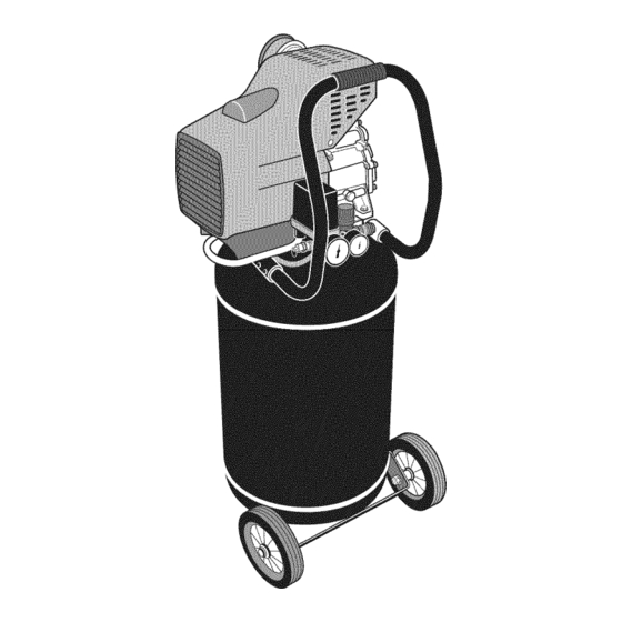
Featuresand Controls Air Compressor Read this Operator's Manual and safety rules before operating your air compressor. Compare the illustrations with your air compressor, to familiarize yourself with the locations of various controls and adjustments. Save this manual for future reference. <b A- ON- OFFSwitch-- Pull to ONposition to power air... -
Page 12: Air Tools
Air Tools Read this Operator'sManual and safety rules before operating your air tools......... Compare the illustrations with your air tools, to familiarize yourself with the locations of various controls and adjustments. Save this manual for future reference. 1/2" Drive impact Tool Air Blow GunTool 3/8"... -
Page 13: Operation
ExtensionCords Operation NOTE:Avoid use of extension cords. Air Compressor OperatingLocation The air compressor should be located where it can be directly plugged into a grounded outlet. DO NOT use an Locate the air compressor in a clean, dry and well-ventilated extension cord unless absolutely necessary. -
Page 14: Starting Yourair Compressor
NOTE:Always drain air tank over a washable surface or in a Compressor Operation suitable container to prevent damaging or staining surfaces. You do not have to use the maximum operating pressure at 4. Pull ON - OFF switch to ON position. Compressor will all times because the air tool being used often requires less start. -
Page 15: Air Tooloperation
3/8 in. Drive Ratchet Wrench Air ToolOperation This ratchet wrench is designed for removing and installing This section will describe proper operation for each tool different engine parts such as water pumps, radiators, and supplied in the kit. so forth. It is idealfor use in confined areas where hand Before each use, drain water out of the air compressor tank tools are cumbersome. - Page 16 AirBlow Needle inflator CAUTION!Never aim air stream at living things. Ensure other To use a needle inflator to inflate a basketball or volleyball, people in the spray area are wearing safety goggles and dust for example: masks, as appropriate. 1. Connect tire inflation tool to air supply. WARNING 2.
-
Page 17: Maintenance
Maintenance Air Tool Maintenance Other than daily lubrication, air tools need little maintenance. GeneralRecommendations • Use a soft cloth or shop towel to wipe off any dirt or oil. To ensure efficient operation and longer life of the air compressor and air tools, prepare and follow a routine •... -
Page 18: Inspect Tank Drain Valve
Inspect Tank Drain Valve Changing Pump Oil 1. Push ON- OFF switch to OFFand unplug unit. At recommendedoil change interval, follow these steps: 2. Disconnect air tool or accessory from unit. WARNING 3. Pull ring on safety valve to reduceair pressure. Release safety valve ring. - Page 19 Use a soft cloth and a small brush for cleaning 3. Remove air filter media (6). accumulated dirt and debris from the following IMPORTANT:DO NOToperate compressor with air filter locations: media removed. • Louvers on left hand end of motor shroud (A) If dirty, use compressed air to dislodge dirt from air (when viewed from rear of unit) filter media.
-
Page 20: Storage
Air Compressor Storage Storage Beforeyou store your air compressor, make sure you Air Tool Storage perform the following: The ratchet wrench and impact tool must be lubricated 1. Review Maintenance and perform scheduled before storing. See Air Motor Lubrication in Assembly. maintenance as necessary. -
Page 21: Troubleshooting
Troubleshooting Before You Call If you have any problems with the operation of your air compressor or air tools, please call the air compressor helpline at (800) 743-4115. if calling for assistance, please have the model, revision, and serial number information printed on the identification label available. -
Page 22: Air Compressor Troubleshooting Chart
Air Compressor Troubleshooting Chart CAUSE CORRECTION PROBLEM Pressure switch does not shut off motor Move ON - OFFswitch to OFFposition. Excessive tankpressure - Safety Contact trained service technician. when compressor reaches "cut-out" Valvepopsoff. pressure or "cut-off" setting too high. 1. Quick connect fitting cracked or 1. - Page 23 CAUSE CORRECTION PROBLEM 1. Decreaseamount of air used. 1. Prolonged excessiveuse of air. 2. Compressor is not large enough for air 2. Check the accessory requirement. If it is higher requirement. than the CFM or pressure supplied by your air Compressor is not compressor, you need a larger capacity air supplying enough air to...
-
Page 24: Glossary
Cut-Out Pressure- While the compressor is running, air is Glossary being produced and stored in the air tank. If no air is being Becoming familiar with these terms will help you understand used, air pressure wiii build in the tank. The pressure switch and operate most air compressors: senses this high pressure and at a certain high level, it turns Air Delivery - A combination of psi and CFM. -
Page 25: Warranty
Effective March 1, 2008; replacesall undated Warranties and all Warranties dated before March 1,2008 LiMiTED WARRANTY Briggs & Stratton Power Products Group, LLC will repair or replace, free of charge, any part(s) of the air compressor that is defective in material or workmanship or both. -
Page 26: Productspecifications
r Compressor ProductSpecifications Air Tools Air Compressor AC Frequency: ......60Hz Air Impact Tool Rated AC Voltage: ....120 Volts, single phase Square Drive ......... 1/2" Pump Type: ....Oil Lubricated Direct Drive FreeSpeed ......7,000 RPM Lubricant: ..... SAE 5W50 or 85W140 Synthetic Max Torque ...... - Page 27 aire Compresor d e IVlanuaJ del 0 BRIGGS& STRATTON POWERPRODUCTS GROUP,LLC JEFFERSON, W ISCONSIN,U.S.A.
- Page 28 IVluchasgracias por comprar este compresor de aire Briggs & Stratton de gran calidad. Nos alegra que haya depositado su confianza en la marca BRUTE Siempre que sea utilizado de acuerdo con las instrucciones de este manual, su compresor de aire Briggs & Stratton le proporcionar_ muchos a_os de buen funcionamiento. Este manual contiene informaciCn de seguridad sobre los riesgos asociados con las compresors de aire y sobre cCmo evitarios.
- Page 29 labia de Contenido Seguridad de Operario ......Descripci6n del equipo ........Reglas de seguridad .......... Montaje ........Montaje de la compresor de aire ......... Montaje de la herramientas neum_ticas ......Caracteristicas y mandos ......Compresor de aire ........... Herramientas neum_ticas ........Operando ........
-
Page 30: Seguridadde Operario
Seguridadde Operario Reglas de seguridad Descripci6ndei equipo I_stees el sirnbolode aierta de seguridad.Sirve para advertir al usuariode un posibie riesgo para su integridadfisica. Siga todos los mensajes de seguridad que figuren despu_s de este sirnboJo Lea atentamente este manual y familiaricese con la compresorde aim. -
Page 31: Espa_Ol
ADVERTENCIA ADVERTENCIA La corrosi6n interna y ocuita del tanque puede )rovocar una explosi6n vioienta con el resultado manual, se pueden producir da_os materiales, Si no se leen y siguen las instrucciones del lesiones o incluso la muerte. de lesiones y/o da_os materiales de gravedad. •... - Page 32 AVlSO ADVERTENCIA El aire comprimido no es respirable y puede Si no se siguen al pie de la letra las instrucciones de uso )rovocar lesiones. inicial, la unidad puede sufrir da_os graves. • Este procedimiento se debe realizarantes de poner ei La inhalaci6n o digesti6n de algunos disolventes compresor en servicio y siempre que se cambie ia v6Jvulade y pinturas puede provocar n_useas,desmayos o...
-
Page 33: Montaje
IVlontaje 3. Introduzca una arandela plana M8 (A) en un perno M8- 1,25 x 30 (B). iVlontajede la compresorde aire Desernbalaje de la cornpresor de aire 1. Saque de la caja los accesodos y el material de embalaje. 2. Abra completamente la caja de carton cortando cada una de sus esquinas de arriba abajo. - Page 34 7. Vuelva a colocar el compresor en la posici6n normal de Afiadir aceite y instaiaci6ndei tap6n dei respiradordei aceite de ia bomba funcionamiento (apoyado en las ruedasyen los soportes de caucho). 1. Aseg0rese de que el compresor est_ apoyado en una superficie plana y nivelada.
-
Page 35: Montaje De La Herramientas Neum_Ticas
iVlontaje de la herramientasneum ticas IVlanguerade aire Utilice una manguera de aire de 3 m (10 pies) 6 7,5 m La caja del juego de herrarnientasincluye los siguientes (25 pies), di_metro interno minimo (ID), 6,35 mm (1/4 elementos: pulg.), equipado con roscas de NPT de 1/4 de pulg. Las * Llavede impactoneum_tica de 12,7 mm (1/2 pulg.) mangueras m_s largas de 7,5 m (25 pies) deber_n tenet un , Llavede trinquete neum_tica de 9,5 mm (3/8 de pulg.) - Page 36 Lubricaci6ndel motor neurn_tico Otras recornendaciones IMPORTANTE: E stasherrarnienlas requieren lubricaci6n Estas herramientas neum_ticas requieren lubricaci6n durante ANTESdei uso initial y ANTESy DESPUES de ¢ada uso ei funcionamiento; esto ayudar_ a prolongar la vida Otil. adicional durante la vida dtil de la herrarnienta. Como se muestra a continuaci6n, el compresor suministra aire (A), pasa a trav6s de un filtro de agua (B), un regulador Para lubricar correctamenlela herramienla neum_tica:...
-
Page 37: Caracteristicas Y Mandos
Caracteristicas y mandos Compresor de aire Lea el Manual del Operario y las reglas de seguridadantes de porteren rnarchasu rn_quinacompresorde aire. Compare las ilustraciones con su m_quina compresor de aire para familiarizarse con las ubicaciones de los diferentes controles y ajustes. Guarde este manual para referencias futuras. A - Interrupter ON - OFF -- Sit_e el interruptor en la posici6n ON J - Bomba del compresorde aire -- La bomba comprime el aire (pulsado) para conectar el compresor de aire. -
Page 38: Herramientas Neum_Ticas
Herramientasneum_ticas Lea este manual del operario y las norrnasde seguridadantes de utilizar las herrarnientasneurn_ticas......... Compare estas ilustraciones con las herramientas neum_ticas para familiarizarse con la situaci6n de los distintos mandos y ajustes. Guardeeste manual para futuras consultas. Herrarnientade irnpactocon accionarniento neurn_tico de 1/2 pulg. -
Page 39: Operando
Operando Cablesprolongadores NOTA:No utiiice cables proiongadores! Colocaci6ndel compresor El compresor de aire debe colocarse en un lugar desde el que pueda enchufarse directamente a una toma de muro con Coloque el compresor de aire en una zona limpia, seca y conexiOna tierra. -
Page 40: Puesta En Marcha Del Compresor De Aire
NOTA:Vaciesiempre el depOsito de aire sobre una superficie Uso del cornpresor lavable o en un contenedor adecuadopara no da_ar ni No es necesario utilizar en todo momento la m_xima presi6n manchar las superficies. de trabajo, ya que ias herramientas neum_ticas suelen 4. -
Page 41: Funcionamiento Del Herramienta Neum_Ticas
Funcionamienlo del herramienlaneurn_licas Para retirar las tuercas, ajuste el regulador de la herramienta al valor m_ximo presionando y girando el pomo moleteado En esta secciOnse describe el funcionamiento correcto de hasta la posiciOn 4. cada una de las herramientas incluidas en el juego. Para instalar las tuercas, ajuste el regulador a su valor Antes de cada uso, purgue el agua del tanque del compresor minimo (1) o medio (2 o 3). - Page 42 Para retirar los pasadores,gire la palancade sentido inverso Para utiNzarla pistola de aire: hasta la "R" o HACIALA IZQUIERDApor completo. Presione 1. Conecte la boquilla deseadaa la pistola y apri6tela a la palancadel gatiNopara activar la herramienta. mano. 2. Conecte la pistola de aire comprimido a la alimentaci6n Otros accesorios incinidos de aire.
-
Page 43: Ivlantenimiento
IVlantenimiento iVlantenimiento de las herramientasneumdticas Adem_s de la lubricaci6n diaria, las herramientas neum_]ticas Recomendaciones generales requieren poco mantenimiento. • UtiNceun paso suave o una toaNade taller para Nmpiar A fin de garantizar un funcionamiento eficaz del compresor cualquier suciedad o aceite. de aire y de prolongar su vida Otil, prepare y siga un programa de mantenimiento rutinario. - Page 44 Si la v_lvula queda pegada o no funciona con suavidad, 4. Si el nivel del aceite de la bomba es insuficiente, quite se deber_ reemplazar por otra nuevadel mismo tipo. el tap6n del respirador dei aceite (C) del orificio de Lleve la unidad a un servicio t6cnico autorizado para Ilenado de aceite (D) y aSada el aceite recomendado repararla.
- Page 45 Limpieza dela unidad Inspeeeione / limpie el filtro de aire Mantenga el compresor de aire limpio y seco, situ_ndolo Siga estos pasos para comprobar y limpiar el filtro de aire lejos de cualquier fuente de contaminaci6n. Aseg0rese de del compresor. que la unidad est_ colocada en una zona bien ventiiada.
-
Page 46: Almacenamiento
Cornprobar las v_lvulas de adrnisi6ny escape de la bornba Alrnacenamienlo del cornpresorde aire Una vez al a_o, es necesario inspeccionar algunos Antes de guardar el compresor de aire, asegOresede seguir componentes internos del compresor. Pidale a un t6cnico estos pasos: cualificado que realiceesta revisi6n e incluya ia admisi6n de 1. -
Page 47: Resoluci6N De Problemas
Resoluci6n de Problemas Antesde Ilamar Si tiene alg0n problema con el funcionamiento del compresor de aire, Ilame a la linea de asistencia (800) 743-4115. Tengapreparados los n0meros de modelo, revision y serie, que figuran en la etiqueta de datos. Tabla de resoluci6nde problemasde las herramientasneum_ticas PROBLEIVlO ACCION... -
Page 48: Tablade Resolucionde Problemas Del Compresor De Aire
Tabla de resoluci6nde problernasdel compresorde aire PROBLEM0 ACCION CAUSA El presostato no para el motor cuando el Sit_e el interruptor ON - OFFen la posici6n OFF.Si Exceso de presi6n en el dep6sito - compresor alcanza la presi6n de "corte" o _sta la unidad no se para, p6ngase en contacto con un la v_lvulade seguridad se activa. - Page 49 PROBLEMO ACCION CAUSA Reduzcala cantidad de aire utilizada. Uso excesivamente prolongado del aire. La capacidad del compresor es Compruebe los requisitos del accesorio. Si insuficiente para generar ei caudal de aire superan los SCFM o la presi6n que suministra necesario. el compresor, necesitar_,una unidad de mayor El compresorno surninistraaire capacidad.
-
Page 50: Glosario
Giosario GFCI- Interruptor de corriente de falio de conexi6n a tierra. Dispositivo que detecta un fiujo de corriente en ia gama de La familiarizaci6n con los siguientes t6rminos le ayudar_ a los miliamperios en un circuito el6ctrico de conexi6n a tierra comprender y utilizar mejor el compresor de aire: y activa un tel6 para abrir amos conductores de la linea. -
Page 51: Garantia
Fechade entrada en vigor: 1 de marza de 2008; sustituye a todas las garantias sin fecha y alas de fecha anterior al 1 de marza de 2008 GARANT[A L[IVlITADA Briggs & Stratton Power Products Group, LLC reparar_ o sustituir_ sin cargo alguno cualquier componente del compresor de aire que presente defectos de materiales y/o mano de obra. -
Page 52: Especificaciones Del Producto
Cornpresor de aire Especificaciones d ei producto Herramientasneum ticas Compresor de aire FrecuenciaCA: ......60 Hz Herrarnientade impacto neurn_tica TensiOnnominal CA: ... 120 voltios, monof_sica Accionamiento en _ngulo recto ..12,7 mm (1/2 pulg.) Tipo de bomba: . .Transmisi0n directa lubficada por aceite Velocidad libre ......
Need help?
Do you have a question about the Brute 074005 and is the answer not in the manual?
Questions and answers