Advertisement
Quick Links
Advertisement

Related Manuals for Rangemaster ZEST HOOD


Summary of Contents for Rangemaster ZEST HOOD
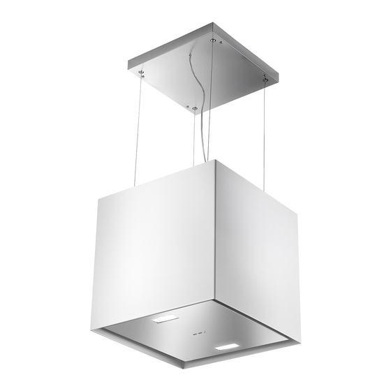
- Page 1 ZEST HOOD Instructions Manual www.rangemaster.co.uk...
-
Page 2: Table Of Contents
INDEX RECOMMENDATIONS AND SUGGESTIONS ........................3 CHARACTERISTICS ................................6 INSTALLATION..................................8 USE ...................................... 16 MAINTENANCE ................................... 18... -
Page 3: Recommendations And Suggestions
RECOMMENDATIONS AND SUGGESTIONS The Instructions for Use apply to several versions of this appliance. Accordingly, you may find descriptions of individual features that do not apply to your specific appliance. INSTALLATION • The manufacturer will not be held liable for any damages resulting from incorrect or improper installation. - Page 4 • If the instructions for installation for the gas hob specify a greater distance specified above, this has to be taken into account. Regulations concerning the discharge of air have to be fulfilled. • Use only screws and small parts in support of the hood. Warning: Failure to install the screws or fixing device in accordance with these instructions may result in electrical hazards.
- Page 5 • “CAUTION: Accessible parts may become hot when used with cooking appliances.” MAINTENANCE • Switch off or unplug the appliance from the mains supply before carrying out any maintenance work. • Clean and/or replace the Filters after the specified time period (Fire hazard). •...
-
Page 6: Characteristics
CHARACTERISTICS Components Ref. Q.ty Product Components Hood Canopy complete with: Controls, Light, Filters, Motor. Hood support plate. Ref. Q.ty Installation Components Wall Plugs ø 10 Screws 4.2 x 44.4 Q.ty Documentation Instruction Manual... - Page 7 Dimensions...
-
Page 8: Installation
INSTALLATION This hood is designed to be mounted on the ceiling/on a shelf, above a free-standing Hob (min. 650 mm), in: • Recirculation version: Internal recirculation. Sequence of operations - Installation • Preparing for installation • Drilling the Ceiling/Shelf and Fixing the support plate •... - Page 9 Ceiling/Shelf drilling and Plate Fixing CEILING/SHELF DRILLING • Use a plumb-line and mark the centre of the cooking hob on the Support Ceiling/Shelf • Rest the Plate against the Ceiling/Shelf, making sure it is the right way up, as shown in the figure.
- Page 10 FIXING THE PLATE • Lift up the Fixing plate and fit the slots onto the two screws previously inserted in the ceiling, and turn until they are at the centre of the ad- justment slot. Warning: The plate must be facing in the direc- tion shown in the figure •...
- Page 11 CONNECTING HOOD-PLATE CABLES N.B. Before proceeding with installation the Hood must be raised to a height of at least 650 mm above the cooker hob by means of a support or with the assistance of another person. Be careful not to exceed the maximum Hood extension indicated in the dimensional drawing.
- Page 12 • Pay attention to the direction in which the Plate is fixed to the ceiling. • Insert the safety knobs (c) into the respective cables, with the thread to the top. • Insert the cable locking screws (b) into the respective cables.
- Page 13 • Pass the Cables into the slots on the threaded pawls (a) and tighten the cable locking screws (b) into the pawls themselves. • When the operation has been completed, the result should be as shown in the figure for all 4 cables.
- Page 14 LEVELLING THE HOOD • The hood canopy must be levelled. • The Hood is levelled by adjusting the safety pawls • Rest a spirit level on the hood. • Exerting an upwards pressure on the safety knobs “unlocks” movement of the Cable. By inserting or extracting the cable from the cable locking screw it is possible to make adjustments to level the mobile hood canopy.
- Page 15 FIXING THE POWER SUPPLY CABLE • Tighten the power supply cable and fix it to the Bracket on the ceiling mounted Plate, using the tongue already mounted and 2 screws. • Slot the rubber cable raceway already threaded onto the power cable into the slot to prevent future damage.
-
Page 16: Use
Control panel Button Function Turns the lights ON/OFF at maximum intensity. Press and hold the button for approximately 4 LED S1 flashes twice = alarm seconds, with all the loads turned off (Motor and Lights), to turn the Activated Charcoal LED S1 flashes once = alarm Filter alarm on/off. - Page 17 REMOTE CONTROL The appliance can be controlled using a remote control powered by a 1.5 V carbon-zinc alkaline batteries of the standard LR03-AAA type (not included). • Do not place the remote control near to heat sources. • Used batteries must be disposed of in the proper manner. Control panel Button Function...
-
Page 18: Maintenance
MAINTENANCE Grease filter The filter must be cleaned every 2 months of operation, or more frequently for particularly heavy usage, and can be washed in a dishwasher. CLEANING METAL SELF- SUPPORTING GREASE FILTER • Open the lighting unit by pulling on the nocth. •... - Page 20 AGA RANGEMASTER GROUP PLC 991.0302.745_ver3 - 161201 D001891_01...
Need help?
Do you have a question about the ZEST HOOD and is the answer not in the manual?
Questions and answers