Table of Contents
Advertisement
INSTALLATION INSTRUCTIONS
®
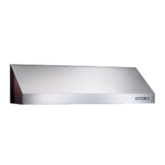
64000 SERIES
RESIDENTIAL USE ONLY
READ AND SAVE THESE INSTRUCTIONS
INSTALLER: LEAVE THIS MANUAL WITH HOMEOWNER.
HOMEOWNER: USE AND CARE INFORMATION ON PAGE 10
BROAN MFG. CO., INC./A NORTEK COMPANY, Hartford, Wisconsin, 1-800-637-1453
V03515 rev C
In Canada: Broan Limited, Mississauga, Ontario, 1-888-88-BROAN
Advertisement
Table of Contents

Summary of Contents for Rangemaster 64000 series
- Page 1 INSTALLATION INSTRUCTIONS ® 64000 SERIES RESIDENTIAL USE ONLY READ AND SAVE THESE INSTRUCTIONS INSTALLER: LEAVE THIS MANUAL WITH HOMEOWNER. HOMEOWNER: USE AND CARE INFORMATION ON PAGE 10 BROAN MFG. CO., INC./A NORTEK COMPANY, Hartford, Wisconsin, 1-800-637-1453 V03515 rev C In Canada: Broan Limited, Mississauga, Ontario, 1-888-88-BROAN...
- Page 2 WARNING WARNING TO REDUCE THE RISK OF FIRE, ELECTRIC SHOCK OR TO REDUCE THE RISK OF INJURY TO PERSONS IN INJURY TO PERSONS, OBSERVE THE FOLLOWING: THE EVENT OF A RANGE TOP GREASE FIRE, OBSERVE THE FOLLOWING*: Use this unit only in the manner intended by the manufacturer.
-
Page 3: Range Hood System
(vertical exhaust only) (supplied with hood) Adapter and damper (supplied with hood) Model 332 KR exterior blower rough-in kit 64000 SERIES HOOD Rough-in kit (supplied with P5 and P8 blowers) Model P8 dual-blower (850 cfm) Model P5 single-blower (500 cfm) Backsplash... -
Page 4: Install Ductwork
1. INSTALL DUCTWORK 2. MEASURE INSTALLATION Plan where and how the ductwork will be installed. Dimensions for the most common installations are shown below. Install proper-sized ductwork, elbows, and roof or wall cap for the type of blower you are installing. If We recommend you to install the hood at a using 7”... -
Page 5: Prepare The Installation
3. PREPARE THE INSTALLATION Make sure that the following items are included: - Range hood - Accessories: • Filters • Bag of parts including: (4) lock nuts, (1) wire clamp, (8) 1/2” double thread screws, (2) wire connectors, (2) 1/2” standard screws, (6) 3/8 screws. •... -
Page 6: Install The Adapter
7. INSTALL THE ROUGH-IN PLATE AND INSTALL THE DEVIATOR Secure the rough-in plate in the hood with 4 lock nuts. YOU MUST also install the deviator if you choose the vertical opening. (see picture below) Note: The deviator will not slide entirely into the hood, you will notice 1/8” will remain. 8. -
Page 7: Install The Hood
9. INSTALL THE HOOD Run power cable to installation location. Place the hood to its location. Mark the position of the screws (smaller part of the key holes) with a pen. Remove the hood and install the (8) 1/2” double thread screws leaving a 1/8” gap (4 screws for 30”... - Page 8 11. INSTALL THE BLOWER (INTERNAL) The blower must be installed to the rough-in plate using (4) 3/8” screws for the single blower unit and (6) 3/8” screws for the dual blower unit. Remove the cover from the blower assembly. Remove the impeller(s) by pulling them out gently (see picture below).
-
Page 9: Light Bulbs
Plug the blower unit into the female receptacle and the power supply into the male connector inside the hood. 12. LIGHT BULBS This range hood uses 50W halogen lamps. (120V, 50W, PAR 20) Install the lights by rotating clockwise. 13. HEAT LAMPS The heat lamps required are 120V, 175W max, infrared bulbs. -
Page 10: Operation
USE AND CARE Grease filters and impeller(s) The grease filters, impeller(s) and grease collection channel should be cleaned frequently. Use a warm detergent solution. Grease filters and impellers are dishwasher safe. Remove filters by pushing filters towards the back of hood and rotating filters downward. Hood cleaning Stainless steel cleaning: How to maintain its «... -
Page 11: Technical Specifications
BLOWER The blower is operated using two (2) controls. Use the red, lighted on/off switch to start and stop the blower. When turned on, the blower will operate at the previous setting of the speed control. Turn the speed control knob clockwise to decrease blower speed – counterclockwise to increase speed. COOKTOP LIGHTING (HALOGEN) A double set of on/off switches controls the halogen lights. -
Page 12: Warranty
WARRANTY BROAN ONE YEAR LIMITED WARRANTY Broan warrants to the original consumer purchaser of its products that such products will be free from defects in materials or workmanship for a period of one year from the date of original purchase. THERE ARE NO OTHER WARRANTIES, EXPRESS OR IMPLIED, INCLUDING, BUT NOT LIMITED TO, IMPLIED WARRANTIES OR MERCHANTABILITY OR FITNESS FOR A PARTICULAR PURPOSE. -
Page 13: Wiring Diagrams
WIRING DIAGRAMS HALOGEN LAMP (50W PAR20) HALOGEN LAMP (50W PAR20) HEAT LAMP 175W GANG SPST Rangemaster ROCKER SWITCH 30” and 36” SPST HEAT LAMP ROCKER 175W SWITCH TERMINAL BLOCK SPST 8 POSITIONS ROCKER SWITCH ACT SMC1270PT SOLID SPST STATE ROCKER SWITCH... -
Page 14: Service Parts
SPST CARLING LIGHTED SINGLE SWITCH V03504 RANGEMASTER SPEED CONTROL BUTTON V03505 RANGEMASTER TERMINAL STRIP V03517 RANGEMASTER 10" POWER CORDS V03518 10" RANGEMASTER CORDS FOR HEAT LAMP V03519 RANGEMASTER 10" CONTROL WIRE V03520 RANGEMASTER 10" LIGHTED SWITCH WIRE V00673 LOCK NUT #8-32 V02512 SCREW #8-32 X 1/2"... - Page 15 SERVICE PARTS SINGLE BLOWER/ROUGH-IN (Model P5) PART NUMBER DESCRIPTION V12997 ROUGH-IN PLATE V13230 OUTLET BOX COVER V13233 BLOWER CHASSIS V13235 BLOWER COVER V13240 CAPACITOR COVER V13296 ADAPTER & DAMPER V01766 MOTOR 165W CW V03400 BLOWER IMPELLER 7.094" x 3.375"CW V02160 CAPACITATOR 15 MFD V02001 MOTOR GROMMET G-431-1...
- Page 16 SERVICE PARTS DUAL BLOWER/ROUGH-IN (Model P8) PART NUMBER DESCRIPTION V12997 ROUGH-IN PLATE V13230 ELECTRIC BOX COVER V13234 BLOWER CHASSIS V13236 BLOWER COVER V13240 CAPACITOR COVER V13296 ADAPTER & DAMPER V01766 MOTOR 165W CW V03457 MOTOR 165W CCW V03400 BLOWER IMPELLER, HOOD 7.094" X 3.375"CW V03399 BLOWER IMPELLER, HOOD 7.094"...


