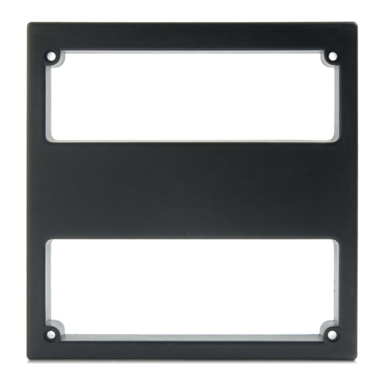
Summary of Contents for Roger LRT-1
- Page 1 Roger Access Control System LRT-1 reader Operating Manual Product version: v1.0 Document version: Rev. A...
-
Page 2: Design And Application
2018-09-06 Design and application LRT-1 is a long range proximity card reader. The reader is offered in a set with MCI-1 interface which enables connection of the reader both to MC16 series access controllers (RACS 5 system ) and PRxx1/PRxx2 series access controllers (RACS 4 system). In all scenarios the reader sends 32bit card number. -
Page 3: Reading Range
Metal objects are irrelevant if located in distance of more than 1m from the reader. In case of LRT-1 installed in distance of 15 cm from metal wall the reading range is approximately reduced by 50%. If the distance is 25cm then the range is reduced approximately by 15%. If the reader is installed in a distance lower than 15 cm from metal wall then card reading might be not possible at all. - Page 4 LRT-1 Operating Manual.doc 2018-09-06 Fig. 3 Arrangement of service contacts Contacts Function The first contact for selection of operating mode (RACS 4 or RACS 5) The second contact for selection of operating mode (RACS 4 or RACS 5) Restart. When contacts are shorted for a moment then interface restarts. After restart, LED_SY (orange) indicator is pulsing for 2s.
-
Page 5: Led Indicators
LRT-1 Operating Manual.doc 2018-09-06 LED indicators LED indicators are located inside the enclosure of MCI-1 and they are visible from the top of the interface. LED indicators are used to signal various states both in programming and normal modes. Communication loss with controller is signalled with synchronic pulsing of all indicators. -
Page 6: Mci-1 Operating Mode
Tab. 2 Number of pulses corresponding to RACS 4 and RACS 5 address MCI-1 operating mode LRT-1 reader can be used both in RACS 4 and RACS 5 systems. The selection of operating mode is done with MD1 and MD2 contacts. - Page 7 LRT-1 Operating Manual.doc 2018-09-06 Configuration with RogerVDM software The address and other settings can be programmed with RogerVDM program (Windows). The connection to computer requires RUD-1 USB-RS485 interface. Procedure for programming with computer: Make connections as in fig. 5 ...
-
Page 8: Mci-1 Configuration Parameters
LRT-1 Operating Manual.doc 2018-09-06 MCI-1 configuration parameters MCI-1 settings are presented in the table below. All these parameters are configured with RogerVDM software within low level configuration of the device. RS485 and RACS CLK/DTA addresses can also be configured manually without computer. -
Page 9: Firmware Update
LRT-1 Operating Manual.doc 2018-09-06 Firmware update Device firmware can be updated with RogerVDM (Windows) software. RUD-1 interface is necessary for such update. Firmware update procedure: Make connections as in fig. 6 Place jumper on FDM contacts Connect RUD-1 to computer USB port ... -
Page 10: Connection To Access Controller
The address must be in range of 100-115 (RACS 5) or 0-3 (RACS 4). The address can be programmed manually while all low level settings can be configured with RogerVDM software. LRT-1 reader must be connected to MCI-1 interface with UTP cable. Unused wires of the UTP cable can be used for power supply. -
Page 11: Installation
Fig. 8 Connection of LRT-1 reader to PRxx1 or PRxx2 access controller Installation 1. LRT-1 reader must be installed on vertical structure (wall, pole) in a place which is free from strong electromagnetic interferences and possibly far from metal objects. -
Page 12: Specification Parameter
Value Power supply 11-15VDC LRT-1 current consumption (average) 290mA MCI-1 current consumption (average) 40mA Cable length between MCI-1 and LRT-1 max. 1200m Cable length between MCI-1 and MC16 max. 1200m controller Cable length between MCI-1 and PRxx1 max. 150m or PRxx2 controller... -
Page 13: Product History
Weight of the equipment is specified in the document. Contact: Roger sp. z o.o. sp.k. 82-400 Sztum Gościszewo 59 Tel.: +48 55 272 0132 Fax: +48 55 272 0133 Tech.


Need help?
Do you have a question about the LRT-1 and is the answer not in the manual?
Questions and answers