Advertisement
Quick Links
LEC-GDN1#-TF222-182EN
ORIGINAL INSTRUCTIONS
Instruction Manual
Gateway (GW) unit
TM
DeviceNet
compatible
Series LEC-GDN1*
The intended use of the gateway unit is to connect to step motor
controllers which control the movement of an electric actuator, while
connected to the DeviceNet network.
1 Safety Instructions
These safety instructions are intended to prevent hazardous situations
and/or equipment damage. These instructions indicate the level of
potential hazard with the labels of "Caution," "Warning" or "Danger."
They are all important notes for safety and must be followed in addition
to International Standards (ISO/IEC)
*1)
, and other safety regulations.
IEC 60204-1: Safety of machinery - Electrical equipment of machines.
(Part 1: General requirements)
ISO 10218-1: Robots and robotic devices - Safety requirements for
industrial robots - Part 1: Robots.
• Refer to product catalogue, Operation Manual and Handling
Precautions for SMC Products for additional information.
• Keep this manual in a safe place for future reference.
Caution indicates a hazard with a low level of risk which, if
Caution
not avoided, could result in minor or moderate injury.
Warning indicates a hazard with a medium level of risk
Warning
which, if not avoided, could result in death or serious injury.
Danger indicates a hazard with a high level of risk which, if
Danger
not avoided, will result in death or serious injury.
Warning
• Always ensure compliance with relevant safety laws and
standards.
• All work must be carried out in a safe manner by a qualified person in
compliance with applicable national regulations.
Refer to the operation manual or catalogue on the SMC website (URL:
https://www.smcworld.com) for further Safety Instructions.
2 Specifications
2.1 General specifications
Item
Specifications
Rated voltage
24 VDC ±10%
200 mA max. (with no teaching box)
Current consumption
300 mA max. (with teaching box)
Applicable controller
Electric actuator controller (LECP6, LECA6)
Connected product
8 pcs. Max. (12 pcs. in step data input mode)
Cooling method
Natural air-cooling
Operating
0°C to 40°C (no freezing)
temperature
Storage temperature
-10
o
C to 60
o
C (no freezing)
Operating humidity
90% RH or less (no condensation)
2
Vibration resistance
4.9 m/s
Enclosure rating
IP20
50 MΩ (500 VDC)
Insulation resistance
between housing (radiation fin) and FG
200 g (Direct mounting type)
Weight
220 g (DIN rail mounting type)
2 Specifications (continued)
2.2 DeviceNet specifications
Item
Specifications
Fieldbus
DeviceNet
TM
Slave type
Group2 Only Server
MAC ID setting range
1 to 63
Occupied area(input/output)
200 byte / 200 byte
Communication speed
125 kbps / 250 kbps / 500 kbps
EDS file
Configuration file
(download from the SMC website.)
Vendor code: 7 (SMC Corporation)
Device Information
Product code: 143
Corresponding message
Poll, Strobe, Change of stats, Cyclic
DeviceNet
TM
power supply
11 to 24 VDC
Terminating resistor
None
Communication speed (kbps)
Maximum cable length
125
250
Thick
500
250
Maximum
cable
network cable
Thin
length (m)
100
cable
156
78
Maximum length of
branch cable (m)
Max. length of one branch line 6 m.
2.3 Controller I/F communication specifications
Item
Specifications
Serial
RS485 (Modbus protocol compatible)
communication
Communication
115.2 kbps or 230.4 kbps (select 115.2 kbps
speed
when the teaching box is connected)
The cable for the teaching box (3 m) and the
electric actuator controller (3 m x 8) = 27 m.
This is the maximum allowable cable length.
Cable length
・・・
3m
3m
3m
3m
Warning
Special products (-X) might have specifications different from those
shown in this section. Contact SMC for specific drawings.
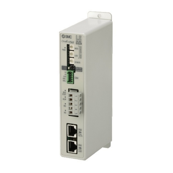
3 Name and function of parts
No.
Name
Description
1
LED display
LED to indicate the gateway status.
2
NODE address switch
Switch to set address LSD / MSD.
B RATE communication
Switch to set the communication
3
speed switch
speed to the controller IF.
To enable communication with
CN2 SW communication
4
equipment on CN2 and disable
switch
communication with controller IF.
5
CN4 power connector
Connection for power supply / EMG.
6
CN3 bus connector
Connection for DeviceNet.
Connection for teaching box or PC
7
CN2 TB / PC connector
with controller setting software.
8
CN1 CONT connector
Connection for controller IF.
4 Installation
4.1 Installation
Warning
• Do not install the product unless the safety instructions have been read
and understood.
4.2 Mounting
• The gateway can be direct mounted (model LEC-GDN1) using 2 x M4
screws or mounted on a DIN rail (model LEC-GDN1D).
• When using DIN rail mounting, hook the gateway on the DIN rail and
press the lever in the direction of Arrow A to lock it.
Direct mounting
DIN rail mounting
Screw direction
500
100
39
Screw direction
4.3 Environment
Warning
• Do not use in an environment where corrosive gases, chemicals, salt
water or steam are present.
• Do not use in an explosive atmosphere.
• Do not expose to direct sunlight. Use a suitable protective cover.
• Do not install in a location subject to vibration or impact in excess of
the product's specifications.
• Do not mount in a location exposed to radiant heat that would result in
3m
temperatures in excess of the product's specifications.
• Avoid mounting the gateway near a vibration source, such as a large
electromagnetic contactor or circuit breaker on the same panel.
• Do not use in an environment with strong magnetic fields present.
5 Wiring
5.1 Wiring
Caution
• Do not perform wiring while the power is on.
• Confirm proper insulation of wiring.
• Do not route wires and cables together with power or high voltage
cables.
• Keep wiring as short as possible to prevent interference from
electromagnetic noise and surge voltage.
• Do not use an inrush current limited type of power supply for the
gateway.
• Do not connect multiple wires to one connector terminal.
5.2 Power Supply Connector (CN4)
Wire the power supply cable to the power supply plug connector, then
insert it into connector CN4 on the gateway.
• Use special screwdriver (Phoenix Contact
No. SZS0.4×2.0) to open / close the lever
and insert the wire into the connector
terminal.
• Applicable wire size:
Wire entry
2
20 AWG (0.5 mm
).
No.
Terminal
5
FG
4
0V
3
24V
2
EMG-
1
EMG+
5 Wiring (continued)
5.3 Ground connection
• Connect a ground wire to the FG terminal (pin 5) on the power supply
connector (CN4).
FG terminal
The M4 screw, cable with crimped terminal and shakeproof washer must
be prepared by the user.
The gateway must be connected to Ground to shield it from electrical
noise.
• A dedicated Ground connection must be used. Grounding should be
DIN rail
to a D-class ground specification (resistance of 100 Ω maximum).
• The cross-sectional area of the ground cable shall be 2 mm
• The Grounding point should be as near as possible to the gateway.
Keep the grounding cable as short as possible.
Gateway
Other
device
unit
Recommended FG
5.4 Bus connector (CN3)
No.
1
1
2
2
3
3
4
4
5
5
• Use the DeviceNet
TM
connector with bus cable.
• A shielded twisted pair cable for DeviceNet
• A terminating resistor (121 Ω ± 1%,1/4 W) must be connected to the
branch connector at the terminal.
Lever
Description
FG terminal
Power supply -
Power supply +
EMG output -
EMG output +
Lever
Caution
2
minimum.
Gateway
Other
unit
device
Not Recommended
Terminal
Description
Power supply (-) for
V-
DeviceNet
TM
CAN_L
CAN bus line (L)
SHIELD
Shield
CAN_H
CAN bus line (H)
Power supply (+) for
V+
TM
DeviceNet
Caution
TM
should be used.
Page 1 of 2
Advertisement

Related Manuals for SMC Networks LEC-GDN1 Series


Summary of Contents for SMC Networks LEC-GDN1 Series
- Page 1 LEC-GDN1#-TF222-182EN 2 Specifications (continued) 4 Installation 5 Wiring (continued) ORIGINAL INSTRUCTIONS 2.2 DeviceNet specifications 4.1 Installation 5.3 Ground connection • Connect a ground wire to the FG terminal (pin 5) on the power supply Warning Item Specifications connector (CN4). Instruction Manual Fieldbus DeviceNet •...
- Page 2 LEC-GDN1#-TF222-182EN 6 Wiring Diagram 7 How to Order The system structure for using the Gateway unit is shown below. Refer to the catalogue on the SMC website (URL: https://www.smcworld.com) for the How to Order information. ●Teaching box 8 Outline Dimensions (mm) LEC-T1-3#G# DeviceNet Terminating...
Need help?
Do you have a question about the LEC-GDN1 Series and is the answer not in the manual?
Questions and answers