Advertisement
EX500-TFK41GB-A
Installation & Maintenance Manual
EtherNet/IP
Compatible GW Unit
TM
Type EX500-GEN1
1 Safety Instructions
•
This manual contains essential information for the protection of users
and others from possible injury and/or equipment damage.
• Read this manual before using the product, to ensure correct handling,
and read the manuals of related apparatus before use.
• Keep this manual in a safe place for future reference.
• These instructions indicate the level of potential hazard by label of
"DANGER", "WARNING" or "CAUTION", followed by important safety
• To ensure safety of personnel and equipment the safety instructions in
information which must be carefully followed.
this manual and the product catalogue must be observed, along with
other relevant safety practices.
If instructions are not followed there is a possibility of
WARNING
serious injury or loss of life.
If instructions are not followed there is a possibility of
CAUTION
injury or equipment damage.
WARNING
•
Do not disassemble, modify (including change of printed circuit
board) or repair the product.
An injury or product failure may result.
•
Do not operate the product beyond the specification range.
Fire, malfunction or equipment damage may result. Use the product
only after confirming the specifications.
•
Do not use the product in the presence of flammable, explosive or
corrosive gas.
Fire, explosion or corrosion may result. This product does not have an
explosion proof construction.
•
When using the product as part of an interlocking system:
1) Provide a double interlocking system, for example a mechanical
system.
2) Check the product regularly to ensure proper operation.
•
Before performing maintenance, be sure of the following:
1) Turn off the power supply.
2) Stop the air supply, exhaust the residual pressure and verify the
release of air from the system.
CAUTION
•
Always perform a system check after maintenance.
Do not use the product if any error occurs.
Safety cannot be assured if caused by un-intentional malfunction.
•
Provide grounding to ensure correct operation and to improve
noise resistance of the product.
This product should be individually grounded using a short cable.
•
Follow the instructions given below when handling the product.
Failing to do so may result in product damage.
•
Maintenance space should always be provided around the product.
•
Do not remove labels from the product.
•
Do not drop, hit or apply excessive shock to the product.
•
Follow all specified tightening torques.
1 Safety Instructions (continued)
•
Do not bend, apply tensile force, or apply force by placing heavy
loads, on the cables.
•
Connect wires and cables correctly, and do not connect while the
power is ON.
•
Do not route wires and cables together with power or high-voltage
cables.
•
Check the insulation of wires and cables.
•
Take proper measures against noise, such as noise filters, when the
product is incorporated in equipment or devices.
•
Select the required protection (IP) rating according to the environment
of operation.
•
Take sufficient shielding measures when the product is to be used in the
following conditions:
(1) where noise due to static electricity is generated.
(2) where electro-magnetic field strength is high.
(3) where radioactivity is present.
(4) where power lines are located.
•
Do not use the product in a place where electric surges are generated.
•
Use suitable surge protection when a surge generating load such as a
solenoid valve are to be directly driven.
•
Prevent any foreign matter from entering this product.
•
Do not expose the product to vibration or impact.
•
Use the product within the specified ambient temperature range.
•
Do not expose the product to any heat radiation.
•
Use a precision screwdriver with flat blade to adjust the DIP switch.
•
Close the cover over the switches before power is applied.
•
Do not clean the product with chemicals such as benzene or thinners.
•
Power Supply selection
A UL approved direct current (DC) power supply should be used with this
product, as follows:
1. A limited voltage / current supply in accordance with UL508.
A circuit from which power is supplied by the secondary coil of a
transformer according to the following:
Maximum voltage (no load) : Less than 30Vrms (42.4V peak)
Maximum current : (1) Less than 8A (including when short circuited)
(2) Limited by circuit protection (such as a fuse) with the
following rating.
No load voltage (V peak)
Max. current (A)
0 to 20 [V]
5.0
20 to 30 [V]
100 / peak voltage
2. A Class 2 power supply unit in accordance with UL1310, or a power
supply circuit of maximum 30Vrms (42.4V peak) or less, using a Class 2
transformer in accordance with UL1585 as power source.
2 Specifications
Basic specifications
Rated voltage
24VDC
Power supply for input and controlling GW/SI :
Range of power
24VDC
10%
supply voltage
Power supply for output : 24VDC+10%/-5% ( Voltage
drop warning at around 20V )
Power supply for input and controlling GW/SI : 3.0A
@ Inside GW unit : 0.2A
(
Rated current
@ Input device and SI control section : 2.8A
Power supply for solenoid valves and output : 3A
Number of input/
Input point : Max. 64/Output point : Max. 64
output points
Higher-level bus
Protocol
Ethernet (IEEE802.3)
Media
100BASE-TX
Communication
10M/100Mbps
speed
(Automatic selection or manual setting)
Max. segment length
100m (328ft)
Max. transceiver number
2 (per segment)
Full duplex/Half duplex
Communication method
(automatic selection or manual setting)
Fieldbus protocol
EtherNet/IP
Release1.0
TM
Input
: 16 byte ( assembly instance : 100 )
I/O message
Output : 16 byte ( assembly instance : 150 )
Port No.
44818 (0xAF12)
192.168.0.1 to 192.168.0.254 ( Setting by an
IP address setting range
internal switch )
Or optional setting by the DHCP server
Vendor ID
: 7 ( SMC Corp. )
Device information
Product type : 12 ( communication adapter )
Product code : 104
3 How to Order
EX500
GEN1
Communication protocol
EN1
EtherNet/IP
4 Installation
Thread mounting
Secure at four positions with screws with head diameter of 5.2 or more and
thread length of 15mm or more.
148
4 M5
Tightening torque :
(1.5 0.2) N m
Cutout Dimensions for Mounting ( Tolerance :
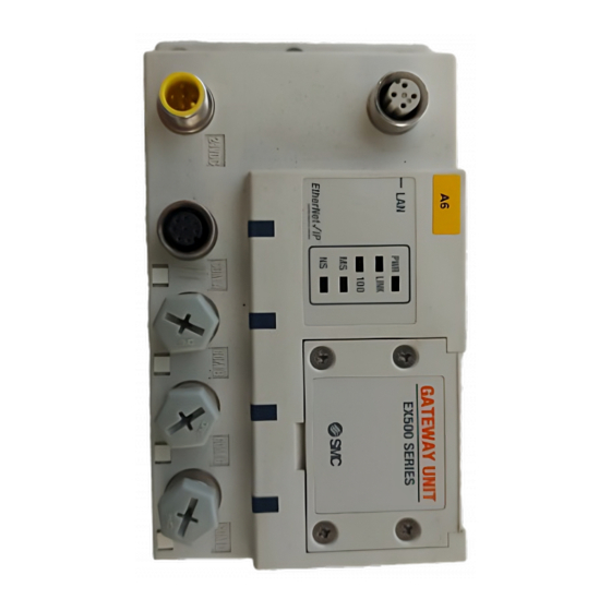
Display
GATEWAY UNIT
LAN
EX500 SERIES
PWR
LINK
100
MS
NS
)
COM A
COM B
COM C
Display
Contents
OFF
The power supply for solenoids is insufficient
PWR
Green light ON
The power supply for solenoids is normal
OFF
The power supply is OFF/initialized
LINK
Green light ON
Ethernet communication established
Green flashing
Data sent/received
OFF
Communication at 10Mbps
100
Green light ON
Communication at 100Mbps
OFF
The power supply is OFF
Green light ON
Operating normally
MS
Green flashing
Setting error
Red flashing
Recoverable internal error
Red light ON
Unrecoverable internal error
OFF
The power supply is OFF/IP address not set
EtherNet/IP-level communication not
Green flashing
established
Multiple EtherNet/IP-level
NS
Green light ON
communications established
Multiple EtherNet/IP-level
Red flashing
communications time out
Red light ON
IP address duplicated
OFF
No input data
COM A
Green light ON
Input data received
OFF
No input data
COM B
Green light ON
Input data received
OFF
No input data
COM C
Green light ON
Input data received
OFF
No input data
COM D
Green light ON
Input data received
NOTE
When connecting manifold valve only without connecting Input unit manifold,
LEDs of COM A to D do not light. To make them light, connect a terminal plug to
the unused connector of SI unit ( "C1" or "0" ).
0.2 )
COM D
Advertisement
Table of Contents

Related Manuals for SMC Networks EX500-GEN1


Summary of Contents for SMC Networks EX500-GEN1
- Page 1 • Do not route wires and cables together with power or high-voltage EX500 SERIES supply voltage Power supply for output : 24VDC+10%/-5% ( Voltage Type EX500-GEN1 cables. LINK drop warning at around 20V ) • Check the insulation of wires and cables.
- Page 2 EX500-TFK41GB-A 5 Display / Setting (continued) 6 Outline dimensions (mm) 8 Wiring Switch setting GW Unit body Communication wiring Power supply wiring Open the station number switch protective cover and set the switches Connect the cable with Ethernet communication connector to the Connect the power supply connector cable to the power supply with a sharp-pointed watchmakers screwdriver etc.
- Page 3 EX500-TFK41GB-A 8 Wiring (continued) Separate wiring for power supply for solenoid valves/output and for input and control of GW/SI Both single power supply and two power supply systems can be adopted, however, the wiring shall be made separately ( for solenoid valves/output and for input and controlling GW/SI ) for either system.
Need help?
Do you have a question about the EX500-GEN1 and is the answer not in the manual?
Questions and answers