Table of Contents
Advertisement
Quick Links
UM2546
User manual
STM32G071B-DISCO USB-C Discovery kit
Introduction
The STM32G071B-DISCO USB-C Discovery kit comes on top of the STM32Cube™ as a
firmware package that offers a full set of software components based on a modular
architecture allowing each module to be used separately in standalone sink applications.
The STM32G071B-DISCO USB-C Discovery kit may be executed in two different modes
depending on the position of the switch: standalone sink mode, or spy mode. The spy mode
does not use the USBPD stack. In this mode, the protocol information on the CC lines is
decoded, and no protocol action may be triggered. But in the standalone sink mode, some
protocol actions may be executed.
In both modes, the UCPD block port 1 is used, and may give an example for a customer
application.
The STM32G071B-DISCO USB-C Discovery kit has been designed to run on
STM32G071B-DISCO (MB1378).
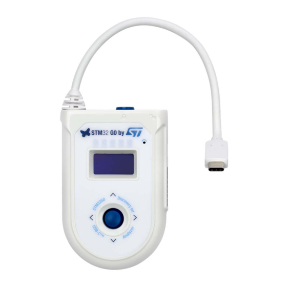
Figure 1. STM32G071B-DISCO USB-C Discovery kit
February 2019
UM2546 Rev 1
1/30
www.st.com
1
Advertisement
Table of Contents

Related Manuals for ST STM32G071B-DISCO


Summary of Contents for ST STM32G071B-DISCO
-
Page 1: Figure 1. Stm32G071B-Disco Usb-C Discovery Kit
STM32G071B-DISCO USB-C Discovery kit Introduction The STM32G071B-DISCO USB-C Discovery kit comes on top of the STM32Cube™ as a firmware package that offers a full set of software components based on a modular architecture allowing each module to be used separately in standalone sink applications. -
Page 2: Table Of Contents
Hardware settings ......... . 14 STM32G071B-DISCO board ........14 Software settings . - Page 3 UM2546 Contents 5.2.5 Dynamic memory use ........25 Middlewares .
- Page 4 List of tables UM2546 List of tables Table 1. STM32G071RBT peripherals used by the UCPD demonstration ....10 Table 2. STM32G071RBT demonstration interrupts usage ....... 10 Table 3.
- Page 5 STM32G071B-DISCO USB-C Discovery kit ........
-
Page 6: Demonstration Description
Figure 2. Demonstration folder organization The demonstration sources are located in the "Projects" folder of the STM32Cube package for each supported board, here in STM32G071B-DISCO folder. The demonstration firmware aims at demonstrating how USB-PD version PD3.0 has been implemented in the context of STM32G0xx devices. -
Page 7: Demonstration Architecture Overview
– SW4STM32: System workbench for STM32 Demonstration architecture overview The top level software architecture of the STM32G071B-DISCO USB-C Discovery kit firmware is represented on Figure 4. The software elements mentioned in this diagram are briefly depicted in dedicated sections. Figure 4. STM32G071B-DISCO USB-C Discovery kit firmware - Software architecture... -
Page 8: Analyzer
Demonstration description UM2546 1.2.1 Analyzer The UCPD Analyzer application uses only one G0 port which mainly consists in Type-C connection/disconnection detection and Type-C power contract negotiation. 1.2.2 HAL level HAL level layer consists in the stm32g0xx.HAL drivers together with the STM32G071B- DISCO board support package (BSP). -
Page 9: Stm32G071Rb Resources
UM2546 Demonstration description STM32G071RB resources 1.3.1 Hardware resources used by the UCPD demonstration Figure 5. STM32G071RBT hardware blocs used by the UCPD demonstration UM2546 Rev 1 9/30... -
Page 10: Peripherals Used By The Ucpd Demonstration
Demonstration description UM2546 1.3.2 Peripherals used by the UCPD demonstration Figure 6. STM32G071RBT peripherals used by the UCPD demonstration Table 1. STM32G071RBT peripherals used by the UCPD demonstration Peripheral Usage description LCD is controlled through SPI1. Write accesses to the LCD are performed to display strings and bitmaps during the UCPD demonstration execution. - Page 11 UM2546 Demonstration description Table 2. STM32G071RBT demonstration interrupts usage (continued) Interrupt Usage description EXTI line 2 Joystick UP (interrupt mode, rising edge) EXTI line 3 Joystick DOWN (interrupt mode, rising edge) EXTI line 7 Joystick RIGHT (interrupt mode, rising edge) EXTI line 1 Joystick LEFT (interrupt mode, rising edge) EXTI line 13...
-
Page 12: Demonstration Functional Description
UM2546 Demonstration functional description Demo startup 2.1.1 Normal processing If the STM32G071B-DISCO is powered from the micro USB, after a board reset, at demo startup the welcome screen is displayed. UCPD demonstration 2.2.1 Mode selection Depending on the position of the switch, the analyzer may run in two modes: Figure 7. -
Page 13: Table 3. Led Assignation
UM2546 Demonstration functional description Table 3. LED assignation Reference Color Name Function Green POWER 5V 5V present onto the board Orange SINK mode Attached to a power source Orange SOURCE mode Attached to a device as source Green SPY mode SPY mode active Green CC1 active line... -
Page 14: Hardware Settings
For detailed information on the hardware part, please check STM32G0 Discovery kit for USB Type-C™ and Power Delivery user manual (UM2401) STM32G071B-DISCO board The STM32Cube demonstration supports STM32G071RB device and runs on STM32G071B-DISCO board from STMicroelectronics. Figure 9. STM32G071B-DISCO top view Figure 10. STM32G071B-DISCO bottom view 14/30 UM2546 Rev 1... -
Page 15: Software Settings
To program demonstration's binary image into the internal Flash memory, the user may exercise STM32G071B-DISCO_USBPD_Analyzer.hex file, thanks to ST-Link Utility or STM32CubeProgrammer. Please refer to the Binary Resources Demo in the Board web page STM32G071B-DISCO (https://www.st.com/en/evaluation-tools/stm32g071b-disco.html). 4.2.2 Using preconfigured projects Select the folder corresponding to the preferred toolchain (MDK-ARM, EWARM or SW4STM32). -
Page 16: Software Description
Software description UM2546 Software description Figure 11. STM32G0 software architecture overview Following sections detail: • Application: in charge to initialize demo application, HAL, interrupt handler and launch the main module • Middleware: FreeRTOS, USBPD Demonstration Application The application goal is to prepare demonstration startup, by initializing all the HW/SW. Table below provides a description of all the actions performed by the different functions in main.c Table 4. -
Page 17: Application Overview
UM2546 Software description The file "stm32g0xx_it.c" is also part of the application and is used, as usual, to map the interrupt vector on the driver HAL driver, depending on the module requirement (for debug trace, and joystick management) Main demonstration functionalities are in the file demo_disco.c. Table 5. -
Page 18: Spy Mode Case
Software description UM2546 5.2.1 Spy mode case In spy mode, the door is open, and the Discovery kit may receive a second plug to spy the messages exchanges. In spy mode, the Discovery kit must not interfere with the two type C devices to which it is connected. -
Page 19: Standalone Sink Case
UM2546 Software description Figure 13. Menu sequence in spy mode 5.2.2 Standalone sink case In standalone mode, the board is in captive cable configuration. Only CC1 line is used for power delivery protocol exchanges. In this mode, application may boot from the VBUS provided by the source. So dead battery indication may be provided and Rd resistors on the CC1 line must be shown. -
Page 20: Demonstration Menu Details
Software description UM2546 Figure 14. Menu sequence in standalone sink mode 5.2.3 Demonstration menu details Figure 15. Welcome screen When the G0 disco is powered on (if micro USB is plugged or VBUS driven on the type C cable) this screen is visible. Figure 16. -
Page 21: Figure 18. Power Screen
UM2546 Software description Figure 18. Power screen When the source capabilities are seen over the CC lines, the maximum power profile is displayed. Figure 19. Power role screen This screen will indicate if the power role swap is supported by the connected source device. -
Page 22: Stm32Cubemonitor Usb Type-C Pd Tool With G0 Discovery Kit
Software description UM2546 This screen displays the current VBUS power: voltage and current, and calculated power. Figure 24. Source profile screen This screen displays all source power profiles. The user scrolls the list via the joystick. In case of standalone sink mode, he may request a dedicated power profile using the joystick (center click on the desired profile) Figure 25. -
Page 23: Figure 28. Stm32Cubemonitor Usb Type-C Pd Tool Debug Trace Selection
UM2546 Software description Figure 28. STM32CubeMonitor USB Type-C PD tool debug trace selection Figure 29. STM32G0 top and bottom view of Discovery board (MB1378) UM2546 Rev 1 23/30... -
Page 24: Figure 30. Trace Example
Software description UM2546 The user gets such a screen: Figure 30. Trace example When the G0 disco application is used in standalone sink mode, the full STM32CubeMonitor USB Type-C PD tool application (GUI) may be used to issue some commands like a data role swap for example. 24/30 UM2546 Rev 1... -
Page 25: Dynamic Memory Use
UM2546 Software description Figure 31. Full STM32CubeMonitor USB Type-C PD tool example For more details see STM32CubeMonitor-UCPD software tool for USB Type-C™ Power Delivery port management user manual (UM2468). 5.2.5 Dynamic memory use The demonstration is currently using: • CSTACK = 0x300 •... -
Page 26: Footprint
Footprint UM2546 Footprint This chapter sums up Ram / Rom consumption per software blocks. Here is a full demonstration of the software consumption: Table 7. RAM/ROM consumption Read only code Read/write data Full demonstration software Read only data [Byte] memory [Byte] memory [Byte] STM32CubeMonitor USB Type-C PD 7682... -
Page 27: Acronyms
UM2546 Acronyms Acronyms Table 8. Table of acronyms Acronym Configuration channel USB PD USB Power Delivery Graphical User Interface: UCPD PC monitor application Power Delivery Dual Role Power Fast Role Swap Dual Role Data Vendor Defined Message UM2546 Rev 1 27/30... -
Page 28: Table Of References
Table of references UM2546 Table of references References USB-IF. (2017). Universal Serial Bus Power Delivery Specification rev 3.0. USB-IF. 28/30 UM2546 Rev 1... -
Page 29: Revision History
UM2546 Revision history Revision history Table 9. Document revision history Date Revision Changes 20-Feb-2019 Initial version UM2546 Rev 1 29/30... - Page 30 ST products and/or to this document at any time without notice. Purchasers should obtain the latest relevant information on ST products before placing orders. ST products are sold pursuant to ST’s terms and conditions of sale in place at the time of order acknowledgement.
Need help?
Do you have a question about the STM32G071B-DISCO and is the answer not in the manual?
Questions and answers