Table of Contents
Advertisement
Quick Links
Advertisement
Table of Contents

Related Manuals for Goulds e-1500 Series


Summary of Contents for Goulds e-1500 Series
- Page 1 INSTRUCTION MANUAL P2002884 Rev B Series e-1500...
-
Page 3: Table Of Contents
Table of Contents Table of Contents 1 Introduction and Safety......................3 1.1 Introduction.......................... 3 1.2 Safety............................. 3 1.2.1 Safety terminology and symbols.................3 1.2.2 Safety instruction decals....................4 1.2.3 User safety........................5 1.2.4 Protecting the environment..................6 2 Transportation and Storage...................... 7 2.1 Examine the delivery......................7 2.1.1 Examine the package.................... - Page 4 Table of Contents 6.4 Reassembly.........................23 6.4.1 Assemble the standard mechanical seal (e-1500-F)..........23 6.4.2 Assemble the single mechanical seal (e-1500-S)........... 24 6.4.3 Assemble the box type single mechanical seal (e-1500-S)........24 6.4.4 Assemble the double mechanical seal (e-1500-D)..........25 6.4.5 Assemble the packed stuffing box (e-1500-PF)............26 6.4.6 Install the impeller......................
-
Page 5: Introduction And Safety
1 Introduction and Safety 1 Introduction and Safety 1.1 Introduction Purpose of this manual The purpose of this manual is to provide necessary information for: • Installation • Operation • Maintenance CAUTION: Read this manual carefully before installing and using the product. Improper use of the product can cause personal injury and damage to property, and may void the warranty. -
Page 6: Safety Instruction Decals
1 Introduction and Safety Hazard levels Hazard level Indication A hazardous situation which, if not avoided, will result in DANGER: death or serious injury A hazardous situation which, if not avoided, could result WARNING: in death or serious injury A hazardous situation which, if not avoided, could result CAUTION: in minor or moderate injury Notices are used when there is a risk of equipment... -
Page 7: User Safety
1 Introduction and Safety All series e-1500 Pumps All series e-1500 with optional ITSC/IT EYEBOLTS OR LIFTING LUGS IF PROVIDED ARE DO NOT RUN PUMP DRY. ROTATING COMPONENTS FOR LIFTING ONLY THE SEAL DAMAGE MAY OCCUR. WARNING COMPONENTS TO WHICH DISCONNECT AND LOCK INSPECT PUMP SEAL THEY ARE ATTACHED. -
Page 8: Protecting The Environment
1 Introduction and Safety Precautions before work Observe these safety precautions before you work with the product or are in connection with the product: • Provide a suitable barrier around the work area, for example, a guard rail. • Make sure that all safety guards are in place and secure. •... -
Page 9: Transportation And Storage
2 Transportation and Storage 2 Transportation and Storage 2.1 Examine the delivery 2.1.1 Examine the package 1. Examine the package for damaged or missing items upon delivery. 2. Record any damaged or missing items on the receipt and freight bill. 3. -
Page 10: Long-Term Storage
2 Transportation and Storage All series e-1500 All series e-1500 with optional ITSC/IT Figure 1: Proper lifting method 2.3 Long-term storage If the unit is stored for more than 6 months, these requirements apply: • Store in a covered and dry location. •... -
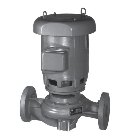
Page 11: Product Description
3 Product Description 3 Product Description 3.1 General description The pump is a centrifugal, in-line, close-coupled pump. These features make the pump easy to install, operate, and service: • High efficiency • Rugged stainless steel-fitted construction • Horizontal or vertical in-line mounting Intended applications WARNING: This product can expose you to chemicals including lead, which is known to the state of... - Page 12 3 Product Description Seal type/ Standard seal, Optional seal, Optional seal, Optional seal, Optional seal, Packing Parameter BUNA/Carbon/ EPR/Carbon / FKM/Carbon / EPR/Silicon EPR/Carbon / Ceramic Tungsten Ceramic Carbide/Silicon Tungsten Carbide Carbide Carbide with external 1,3,4 flush Maximum 50/50% 50/50% 50/50% 60/40% 50/50%...
-
Page 13: Installation
4 Installation 4 Installation 4.1 Preinstallation Precautions WARNING: • When installing in a potentially explosive environment, make sure that the motor is properly certified. • You must ground (earth) all electrical equipment. This applies to the pump equipment, the driver, and any monitoring equipment. Test the ground (earth) lead to verify that it is connected correctly. -
Page 14: Piping Checklist
4 Installation 4.1.3 Piping checklist WARNING: • The heating of water and other fluids causes volumetric expansion. The associated forces can cause the failure of system components and the release of high- temperature fluids. In order to prevent this, install properly sized and located compression tanks and pressure-relief valves. - Page 15 4 Installation Series e-1500 pumps can be installed directly in the piping with pipe hangers adequate to carry the loads from the pump and piping. Figure 2 In many installations, the piping is installed near the ceiling with the pump located close to the floor for ease of maintenance.
- Page 16 4 Installation Figure 5 Alternately with the optional Flange Supports, insolation pads can be used between the support and the floor. Figure 6 Pumps with motors 256 NEMA frame and below can be installed with the shaft horizontal and the piping vertical with supports for the piping (not shown) adequate to carry the loads from the pump and piping.
- Page 17 4 Installation only be used to handle the pump weight as it is not suitable resist loads in other directions. Figure 9 For installations in grooved piping systems when the pump is supported by the piping, flange locking type grooved piping connections are required to prevent the pump from rotating in the piping.
-
Page 18: Commissioning, Startup, Operation, And Shutdown
5 Commissioning, Startup, Operation, and Shutdown 5 Commissioning, Startup, Operation, and Shutdown 5.1 Preparation for startup WARNING: • Failure to follow these precautions before you start the unit will lead to serious personal injury and equipment failure. • Do not operate the pump below the minimum rated flows or with the suction or discharge valves closed. -
Page 19: Prime The Pump
5 Commissioning, Startup, Operation, and Shutdown 5.2 Prime the pump CAUTION: Do not run the pump dry. Make sure that the pump body is full of liquid before startup. If the system does not automatically fill the pump body with liquid, then you must manually prime the pump. 1. -
Page 20: Shut Down The Pump
5 Commissioning, Startup, Operation, and Shutdown Operation at reduced capacity WARNING: Never operate any pumping system with a blocked suction and discharge. Operation, even for a brief period under these conditions, can cause confined pumped fluid to overheat, which results in a violent explosion. You must take all necessary measures to avoid this condition. -
Page 21: Vibration
5 Commissioning, Startup, Operation, and Shutdown 5.7 Vibration After startup, vibration can be measured on the pump bracket at the base of the horizontal (H), vertical (V), and axial (A) directions. The maximum expected value is 0.15 in/sec (3.8 mm/sec) RMS (ANSI/HI 9.6.4) when operating in the Preferred Operating Range (POR) flows from 70% to 120% of the best efficiency point (BEP) (ANSI/HI 9.6.3). -
Page 22: Maintenance
6 Maintenance 6 Maintenance 6.1 Lubrication The pump motor has been lubricated at the factory. Keep the motor properly lubricated in accordance with the motor manufacturer's instructions. 6.2 Disassembly 6.2.1 Disassembly precautions This manual clearly identifies accepted methods for disassembling units. These methods must be adhered to. -
Page 23: Remove The Impeller
6 Maintenance WARNING: Pressurized device. Make sure that the internal pressure is relieved before you continue. 3. Remove the seal flushing line. 4. Remove the volute capscrews. 5. Remove the pump assembly from the volute. 6.2.4 Remove the impeller WARNING: Never apply heat to remove an impeller. -
Page 24: Pre-Assembly Inspections
6 Maintenance Balancing It is recommended that impellers trimmed more than 5% in diameter be rebalanced per ISO 1940 grade G6.3. Angle cut guidelines Model e-1500 5x5x7B pump impellers must be angle cut at reduced diameters according to the following information. ØA ØB Figure 10: 5x5x7B impeller trim —... -
Page 25: Shaft Inspection
6 Maintenance Impeller parts When to replace Vane edges When you see cracks, pitting, or corrosion damage Gaskets, O-rings, and seats replacement • Replace all gaskets and O-rings at each overhaul and disassembly. • Inspect the seats. They must be smooth and free of physical defects. 6.3.2 Shaft inspection Inspection criteria Inspect the shaft according to this criteria:... -
Page 26: Assemble The Single Mechanical Seal (E-1500-S)
6 Maintenance 6.4.2 Assemble the single mechanical seal (e-1500-S) 1. Lubricate the shaft sleeve and seal cap with soapy water. Do not use a petroleum lubricant. 2. Insert a stationary seal with an O-ring into the seal cap and slide it onto the shaft. 3. -
Page 27: Assemble The Double Mechanical Seal (E-1500-D)
6 Maintenance 6. Attach the seal gland to the coverplate. 7. Tighten the capscrews to the seal gland according to the Capscrew torque table. 1. Seal gland 2. Coverplate 3. For 2 in. seal: 55/64 in. (2.813 cm) 4. Seal locking collar 5. -
Page 28: Assemble The Packed Stuffing Box (E-1500-Pf)
6 Maintenance 5. Replace the seal cap gasket. 6. Slide the rotating portion of the seal assembly onto the shaft sleeve. 7. Assemble the coverplate onto the bracket. 8. Tighten the capscrews according to the Capscrew torque values table. 9. Attach the seal cap to the coverplate. 10.Tighten the hex nuts on the seal cap bolts according to the Capscrew torque values table. -
Page 29: Reinstall The Pump Assembly
6 Maintenance 6.4.7 Reinstall the pump assembly 1. Install a new volute gasket. 2. Install the pump assembly into the volute. 3. Tighten the volute capscrews according to the Capscrew torque table. 4. Install a seal flushing tube. 5. Install the drain plug. 6. -
Page 30: Product Warranty
7 Product warranty 7 Product warranty Commercial warranty Warranty. For goods sold to commercial buyers, Seller warrants the goods sold to Buyer hereunder (with the exception of membranes, seals, gaskets, elastomer materials, coatings and other "wear parts" or consumables all of which are not warranted except as otherwise provided in the quotation or sales form) will be (i) be built in accordance with the specifications referred to in the quotation or sales form, if such specifications are expressly made a part of this Agreement, and (ii) free from defects in material and... - Page 31 7 Product warranty materials, coatings and other "wear parts" or consumables all of which are not warranted except as otherwise provided in the quotation or sales form) will be free from defects in material and workmanship for a period of one (1) year from the date of installation or eighteen (18) months from the product date code, whichever shall occur first, unless a longer period is provided by law or is specified in the product documentation (the “Warranty”).
- Page 32 Morton Grove, IL 60053 The original instruction is in English. All non-English instructions are translations of the original instruction. Tel: 1-847-966-3700 Fax: 1-847-965-8379 © 2019 Xylem Inc www.bellgossett.com Goulds is a registered trademark of Goulds Pumps, Inc. and is used under license. P2002884_B_en-US_2019-02_e-1500...
Need help?
Do you have a question about the e-1500 Series and is the answer not in the manual?
Questions and answers