
Related Manuals for Goulds e-530SC Marlow Series


Summary of Contents for Goulds e-530SC Marlow Series
- Page 1 INSTRUCTION MANUAL P2002888 Rev B e-530SC e-531SC Marlow Series e-530SC and e-531SC...
-
Page 3: Table Of Contents
Table of Contents Table of Contents 1 Introduction and Safety......................3 1.1 Introduction.......................... 3 1.2 Safety............................. 3 1.2.1 Safety terminology and symbols.................3 1.2.2 Safety instruction decals....................4 1.3 User safety..........................5 1.3.1 Wash the skin and eyes....................6 1.4 Protecting the environment....................6 2 Transportation and Storage...................... - Page 4 Table of Contents 6.4 Reassembly.........................23 6.4.1 Seal assembly......................23 6.4.2 Assemble the packed stuffing box (e-530SC.e-531SC-PF)........25 6.4.3 Reinstall the rotating assembly and motor..............25 6.4.4 Capscrew torque values.................... 26 6.4.5 Dealer servicing ......................26 7 Product warranty........................27 Marlow Series e-530SC and e-531SC INSTRUCTION MANUAL...
-
Page 5: Introduction And Safety
1 Introduction and Safety 1 Introduction and Safety 1.1 Introduction Purpose of this manual The purpose of this manual is to provide necessary information for: • Installation • Operation • Maintenance CAUTION: Read this manual carefully before installing and using the product. Improper use of the product can cause personal injury and damage to property, and may void the warranty. -
Page 6: Safety Instruction Decals
1 Introduction and Safety Hazard level Indication A hazardous situation which, if not avoided, could result WARNING: in death or serious injury A hazardous situation which, if not avoided, could result CAUTION: in minor or moderate injury Notices are used when there is a risk of equipment NOTICE: damage or decreased performance, but not personal injury. -
Page 7: User Safety
1 Introduction and Safety Make sure that all safety instruction decals are always clearly visible and readable. 1.3 User safety General safety rules These safety rules apply: • Always keep the work area clean. • Pay attention to the risks presented by gas and vapors in the work area. •... -
Page 8: Wash The Skin And Eyes
1 Introduction and Safety Electrical connections Electrical connections must be made by certified electricians in compliance with all international, national, state, and local regulations. For more information about requirements, see sections dealing specifically with electrical connections. Precautions before work Observe these safety precautions before you work with the product or are in connection with the product: •... -
Page 9: Transportation And Storage
2 Transportation and Storage 2 Transportation and Storage 2.1 Examine the delivery 2.1.1 Examine the package 1. Examine the package for damaged or missing items upon delivery. 2. Record any damaged or missing items on the receipt and freight bill. 3. -
Page 10: Long-Term Storage
2 Transportation and Storage Examples Figure 1: Example of a proper lifting method for pump without base Figure 2: Example of a proper lifting method for base mounted pump (e-531SC only) Figure 3: Example of a proper lifting method using lifting lugs for base mounted pump (e-531SC only) 2.3 Long-term storage If the unit is stored for more than 6 months, these requirements apply:... - Page 11 2 Transportation and Storage • Store in a covered and dry location. • Store the unit free from heat, dirt, and vibrations. • Rotate the shaft by hand several times at least every three months. Treat bearing and machined surfaces so that they are well preserved. Refer to the drive unit manufacturer for their long-term storage procedures.
-
Page 12: Product Description
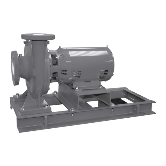
3 Product Description 3 Product Description 3.1 General description Description The pump is a centrifugal, close-coupled pump. The following pump features make it easy to install, operate, and service: • High efficiency • Rugged stainless steel-fitted construction • Footless e-530SC or Foot-mounted e-531SC volute Intended applications WARNING: This product can expose you to chemicals including lead, which is known to the state of... - Page 13 3 Product Description 1. An external flush is required on low pressure systems that contain a high concentration of abrasives. 2. Use packing on open or closed systems which require a large amount of makeup water, as well as systems that are subjected to a wide variety of chemical conditions and solids buildup.
-
Page 14: Installation
4 Installation 4 Installation 4.1 Preinstallation Precautions WARNING: • When installing in a potentially explosive environment, make sure that the motor is properly certified. • You must ground (earth) all electrical equipment. This applies to the pump equipment, the driver, and any monitoring equipment. Test the ground (earth) lead to verify that it is connected correctly. -
Page 15: Foundation Requirements
4 Installation 4.1.2 Foundation requirements Requirements • The foundation must be able to absorb any type of vibration and form a permanent, rigid support for the unit. • The foundation must weigh at least 2-1/2 times the weight of the pump unit. •... -
Page 16: Piping Checklist
4 Installation 4.1.3 Piping checklist WARNING: • The heating of water and other fluids causes volumetric expansion. The associated forces can cause the failure of system components and the release of high- temperature fluids. In order to prevent this, install properly sized and located compression tanks and pressure-relief valves. -
Page 17: Level The Base On A Concrete Foundation For Pump With Base (E-531Sc)
4 Installation go under the pump casing feet to make the volute level with the bottom of the motor support or motor feet. 2. Then add additional shims at each of the four volute hold down bolt locations, as required, until the volute feet are fully supported, the pump discharge flange is level, and there is a gap under the motor saddle or motor feet. -
Page 18: Install The Piping
4 Installation When you pour the grout, remove air bubbles from it by using one of these methods: – Puddle with a vibrator. – Pump the grout into place. 5. Allow the grout to set. It is recommended to remove shims, retighten anchor bolts, and fill shim gaps with grout. -
Page 19: Commissioning, Startup, Operation, And Shutdown
5 Commissioning, Startup, Operation, and Shutdown 5 Commissioning, Startup, Operation, and Shutdown 5.1 Preparation for startup WARNING: • Failure to follow these precautions before you start the unit will lead to serious personal injury and equipment failure. • Do not operate the pump below the minimum rated flows or with the suction or discharge valves closed. -
Page 20: Start The Pump
5 Commissioning, Startup, Operation, and Shutdown 5.3 Start the pump CAUTION: • Observe the pump for vibration levels, bearing temperature, and excessive noise. If normal levels are exceeded, shut down the pump and resolve the issue. Before you start the pump, you must perform these tasks: •... -
Page 21: Shut Down The Pump
5 Commissioning, Startup, Operation, and Shutdown CAUTION: Avoid excessive vibration levels. Excessive vibration levels can damage the bearings, stuffing box or seal chamber, and the mechanical seal, which can result in decreased performance. NOTICE: • Avoid increased radial load. Failure to do so can cause stress on the shaft and bearings. -
Page 22: Maintenance
6 Maintenance 6 Maintenance 6.1 Bearing maintenance Bearing lubrication schedule Type of bearing First lubrication Lubrication intervals Motor bearings No initial lubrication. The motor was Refer to the motor manufacturer's lubricated at the factory. recommendations for lubrication intervals. 6.2 Disassembly 6.2.1 Disassembly precautions This manual clearly identifies accepted methods for disassembling units. -
Page 23: Remove The Mechanical Seal (E-530Sc/E-531Sc And E-530Sc/E-531Sc-F)
6 Maintenance 3. Loosen the rotating assembly from the volute. WARNING: Make certain that the internal pressure of the pump is relieved before you continue. Failure to follow these instructions could result in serious personal injury or death, or property damage. 4. -
Page 24: Pre-Assembly Inspections
6 Maintenance ØA ØB Figure 4: 4–7D impeller trim — 0.125 in. (3.17 mm) increments Hydraulic diameter, nominal, as Diameter at impeller inlet side Trim angle shown on selection curves shroud From maximum diameter 7 in. Use diameter from selection curves 0 degrees, no angle (177.8 mm) to 6.125 in. -
Page 25: Reassembly
6 Maintenance 6.4 Reassembly 6.4.1 Seal assembly 6.4.1.1 Assemble the standard mechanical seal (e-530SC/e-531SC and e-530SC/e-531SC- 1. Lubricate the shaft sleeve and coverplate seal cavity with soapy water. Do not use a petroleum lubricant. 2. Install a new cup gasket and a new seal insert with the indentation side down into the cup. - Page 26 6 Maintenance 6. Tighten the capscrews according to the Capscrew torque table. 7. Attach the seal cap to the coverplate. 8. Tighten the hex nuts on the seal cap bolts according to the Capscrew torque table. 1. O-ring 2. Coverplate 3.
-
Page 27: Assemble The Packed Stuffing Box (E-530Sc.e-531Sc-Pf)
6 Maintenance 1. O-rings 2. Motor end Figure 6: Double mechanical seal (e-530SC/e-531SC-D) 3. Insert another stationary seal and O-ring into the coverplate. 4. Slide the seal cap onto the shaft. 5. Replace the seal cap gasket. 6. Slide the rotating portion of the seal assembly onto the shaft sleeve. 7. -
Page 28: Capscrew Torque Values
6 Maintenance 5. Install a seal flushing tube if it is used. 6. Install the drain plug and close the drain valve. 7. Open the isolation valves and inspect the pump for leaks. Return the pump to service if you do not detect any leaks. See the Note on the packed pump operation in the Commissioning, Startup, Operations, and Shutdown chapter. -
Page 29: Product Warranty
7 Product warranty 7 Product warranty Commercial warranty Warranty. For goods sold to commercial buyers, Seller warrants the goods sold to Buyer hereunder (with the exception of membranes, seals, gaskets, elastomer materials, coatings and other "wear parts" or consumables all of which are not warranted except as otherwise provided in the quotation or sales form) will be (i) be built in accordance with the specifications referred to in the quotation or sales form, if such specifications are expressly made a part of this Agreement, and (ii) free from defects in material and... - Page 30 7 Product warranty materials, coatings and other "wear parts" or consumables all of which are not warranted except as otherwise provided in the quotation or sales form) will be free from defects in material and workmanship for a period of one (1) year from the date of installation or eighteen (18) months from the product date code, whichever shall occur first, unless a longer period is provided by law or is specified in the product documentation (the “Warranty”).
- Page 32 The original instruction is in English. All non-English instructions are translations of the original instruction. Tel: (847) 966-3700 Fax: (847) 965-8379 © 2019 Xylem Inc www.goulds.com Goulds is a registered trademark of Goulds Pumps, Inc. and is used under license. P2002888_B_en-US_2019-02_Marlow Series e-530SC and e-531SC...
Need help?
Do you have a question about the e-530SC Marlow Series and is the answer not in the manual?
Questions and answers