Table of Contents
Advertisement
Advertisement
Table of Contents

Related Manuals for Goulds A-C 2000 Series


Summary of Contents for Goulds A-C 2000 Series
- Page 1 INSTRUCTION MANUAL P2002569 REVISION B Series A-C 2000 CLOSED-COUPLED PUMPS...
- Page 2 NOTE The information contained in this book is intended to assist operating personnel by providing information on the characteristics of the purchased equipment. It does not relieve the user of the responsibility of using accepted engineering practices in the installation, operation and maintenance of this equipment.
-
Page 3: Table Of Contents
TABLE OF CONTENTS Specific Series A-C 2000 Instruction for Close-Coupled Pumps Introduction and safety Introduction .................... 4 Requesting other information ............4 Safety ....................... 4 Safety terminology and symbols ............. 5 Safety instruction decals ..............6 User safety ..................6 Environmental safety ............... -
Page 4: Introduction And Safety Introduction
Introduction and safety Introduction Purpose of this manual The purpose of this manual is to provide necessary information for: • Installation • Operation • Maintenance CAUTION: Read this manual carefully before installing and using the product. Improper use of the product can cause personal injury and damage to property, and may void the warranty. -
Page 5: Safety Terminology And Symbols
Safety terminology and symbols About safety messages It is extremely important that you read, understand, and follow the safety messages and regulations carefully before handling the product. They are published to help prevent these hazards: • Personal accidents and health problems • Damage to the product • Product malfunction Hazard levels Hazard level Indication A hazardous situation which, if not avoided, will result in death or serious DANGER: injury. -
Page 6: Safety Instruction Decals
Safety instruction decals WARNING: The maximum working pressure of the pump is listed on the nameplate. Do not exceed this pressure. Failure to follow these instructions can result in serious personal injury, death, and/or property damage. Alert symbol This safety alert symbol is used in manuals and on the safety instruction decals on the pump to draw attention to safety-related instructions. When used, the safety alert symbol means that failure to follow the instructions may result in a safety hazard. -
Page 7: Environmental Safety
Electrical connections Electrical connections must be made by certified electricians in compliance with all international, national, state, and local regulations. For more information about requirements, see sections dealing specifically with electrical connections. Precautions before work Observe these safety precautions before you work with the product or are in connection with the product: • Provide a suitable barrier around the work area, for example, a guard rail. • Make sure that all safety guards are in place and secure. • Make sure that you have a clear path of retreat. •... -
Page 8: Product Warranty
Product warranty Coverage Xylem undertakes to remedy defects in products from Xylem under these conditions: • The faults are due to defects in design, materials, or workmanship. • The faults are reported to a local sales and service representative within the warranty period. •... -
Page 9: Transportation And Storage Inspect The Delivery
Transportation and storage Inspect the delivery Inspect the package 1. Inspect the package for damaged or missing items upon delivery. 2. Note any damaged or missing items on the receipt and freight bill. 3. File a claim with the shipping company if anything is out of order. If the product has been picked up at a distributor, make a claim directly to the distributor. -
Page 10: Product Description
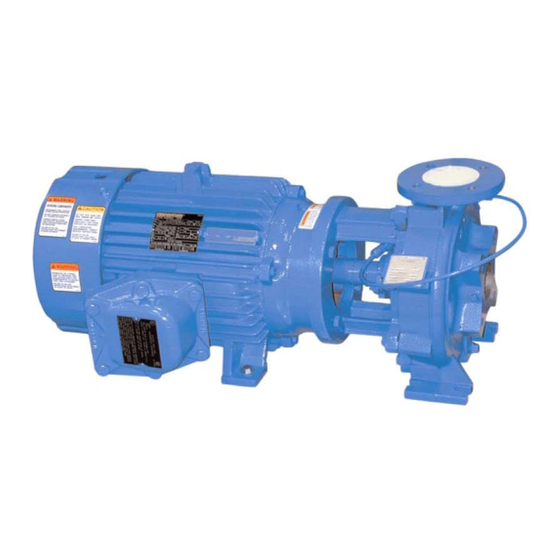
Product description General description The Series A-C 2000 pump is a centrifugal, close-coupled pump. These features make the pump easy to install, operate, and service: • High efficiency • Rugged bronze-fitted construction • Foot-mounted motor Intended applications WARNING: This product can expose you to chemicals including lead, which is known to the State of California to cause cancer or birth defects or other reproductive harm. -
Page 11: Pump Identification
Specific Series A-C 2000 close-coupled pumps instruction Pump identification There are two identification plates on each pump. The pump rating plate gives identification and rating information. Figure 3 shows an example of a typical Rating Plate. Permanent records for this pump are kept by the Serial Number and it must, therefore, be used with all correspondence and spare parts orders. -
Page 12: Disassembly And Reassembly Procedures
Disassembly and reassembly Dismantling the stuffing box A. Pumps with mechanical seals procedures 1. Remove spacer sleeve (1 -154-0). 2. Remove the two nuts holding the gland The procedures outlined in this section cover the (6-014-0) to the stuffing box (2-036-0). dismantling and reassembly of different types of 3. - Page 13 Suction and stuffing box wear ring removal (optional) The optional wear rings are removed from the casing and stuffing box cover by the following method: 1. Drill two axial holes in each wear ring approximately 180 degrees apart being careful not to drill into the casing or stuffing box cover.
- Page 14 4. Place the packing base ring (6-152-0) into the stuffing box. Slide the stuffing box cover over the pump shaft, and, if applicable, bolt the stuffing box to the motor adapter using capscrews (1-904-0). 5. Install the packing (6-924-0) and, if applicable, the seal cage ( 6-013-0) into the stuffing box being sure to stagger the joints as per the instructions found in the general pump...
-
Page 15: Sectional View Drawing
Sectional view drawing... -
Page 16: Ordering Parts
Ordering parts The pumps covered by this manual have been Parts should be ordered as far in advance of their use designed and built with certain replaceable wearing as possible since circumstances beyond the control parts. The recommended inventory of spare parts of the company may reduce existing stock. -
Page 17: General Pump Instructions
Refer to the following paragraphs on " Foundation'', "Baseplate Setting", Goulds Water Technology service organization and "Grouting Procedure''. Experienced, factory-trained servicemen offer prompt, Temporary storage efficient service at reasonable rates. -
Page 18: Foundation
2. Soak top of concrete foundation thoroughly, is to be field mounted, consult factory for then remove surface water. recommendations. Goulds Water Technology 3. Baseplate should be completely filled with grout cannot assume responsibility for final alignment. and if necessary, temporarily use air relief tubing or drill vent holes to remove trapped air. -
Page 19: Suction And Discharge Piping
Figure 9- Setting baseplate and grouting 5. Check the alignment after the foundation bolts the piping system they must be installed beyond the are tightened. piping supports closest to the pump. Tie bolts should 6. Approximately 14 days after the grout has been be used with expansion joints to prevent pipe strain. - Page 20 Suction piping When installing the suction piping, observe the following precautions (See Figure 10). The sizing and installation of the suction piping is extremely important. It must be selected and installed so that pressure losses are minimized and sufficient liquid will flow into the pump when started and operated.
-
Page 21: Stuffing Box
3. Where two or more pumps are connected to the same suction line, install gate valves so that any pump can be isolated from the line. Gate valves should be installed on the suction side of all pumps with a positive pressure for maintenance purposes. Install gate valves with stems horizontal to avoid air pockets. -
Page 22: Packing
Packing lubrication Internal liquid lubricant Pumped liquid may be used to lubricate the packing when the following conditions prevail: 1. Liquid is clean, free from sediment and chemical precipitation and is compatible with seal materials. 2. Temperature is above 32°F and below 160°F. 3. -
Page 23: Operation
Conversion kits may be ordered from your Before initial start of the pump, make the following Goulds Water Technology Sales Representative. inspections: 1. Check alignment between pump and motor Single mechanical seal 2. -
Page 24: Operating Checks
Operating checks This can be used in conjunction with a field test, if one is required. All Goulds Water Technology 1 . Check the pump and piping to assure that there pump tests and curves are based on the "Hydraulic are no leaks. -
Page 25: Vibration
2. The true motor brake horsepower, once the Total head efficiency is determined from dynamometer tests, Total head is the algebraic difference between the can also be calculated from the following formula: total suction and the total discharge heads. kW input x Eff. 1. -
Page 26: Troubleshooting
Motor controls - General External wiring Motor controls should conform to all the electrical Wiring to the motor should be installed in data stamped on the motor data plate. Complete conformance with the National Electrical Code instructions for installation, operation, and and any local codes. - Page 27 Not enough pressure CAUSES CURES 21. Speed too low. See item 5. 22. Air leaks in suction piping. See item 8. 23. Mechanical defects. See items 15, 16 and 17. Dismantle pump and inspect passages of impeller and casing. 24. Obstruction in liquid passages. Remove obstruction.
- Page 28 Pump takes too much power CAUSES CURES 32. Head lower than rating; thereby Machine impeller's OD to size advised by factory. pumping too much liquid. 33. Cavitation See item 14. 34. Mechanical defects See items 15, 16 and 17. 35. Suction inlet not immersed See item 18. enough.
-
Page 29: Maintenance General Maintenance
Maintenance exclude outside liquid. Therefore, it should not be necessary to go beyond the bearings, stuffing box, and coupling when servicing the pump. General maintenance Bearing lubrication - grease Operating conditions vary so widely that to recommend one schedule of preventative Grease lubricated ball bearings are packed with maintenance for all centrifugal pumps is not possible. -
Page 30: Stuffing Box
NOTE: A bearing frame which feels hot to the touch of Packing the hand is not necessarily running hot. Check All pumps are packed before shipment, unless with an accurate temperature measuring device otherwise requested. All packings used are the to be sure. -
Page 31: Mechanical Shaft Seals
Then remove and cut all other rings to the first or suction diffuser, bolted to the suction flange, be supplied by Goulds Water Technology. (If this is not sample. When the rings are placed around the shaft, done, a short section of pipe so designed that it can a tight joint should be formed. -
Page 32: Maintenance Time Table
A faulty foot or check valve will reflect also in poor performance of the pump while in operation. Xylem, Inc. 2881 East Bayard Street Ext., Suite A Seneca Falls, NY 13148 Phone: (800) 453-6777 Fax: (888) 322-5877 www.gouldswatertechnology.com Goulds is a registered trademark of Goulds Pumps, Inc. and is used under license. © 2019 Xylem, Inc. P2002569B February 2019...
Need help?
Do you have a question about the A-C 2000 Series and is the answer not in the manual?
Questions and answers