Table of Contents
Advertisement
Quick Links
850144-01
IM-P693-02
EMM Issue 2
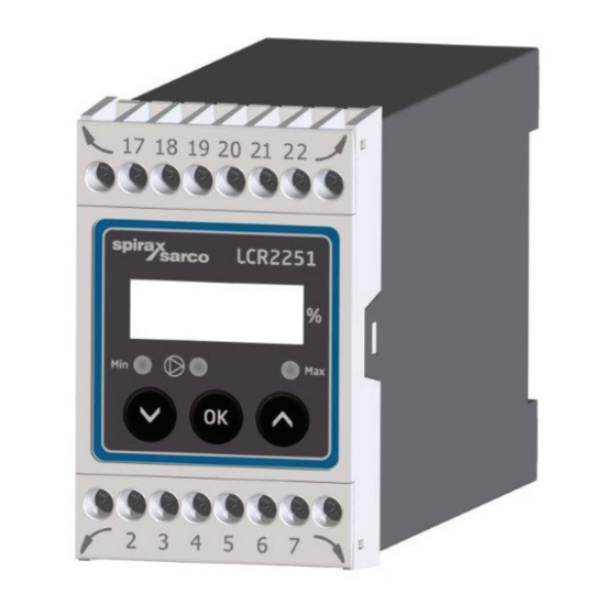
LCR2251
Level Controller
Installation and Maintenance Instructions
1. Safety information
2. General product information
3. Mechanical installation
4. Electrical installation
5. Commissioning
6. Fault finding
7. Technical information
8. Technical assistance
LCR2251 Level Controller
© Copyright 2020
1
IM-P693-02 EMM Issue 2
Printed in Germany
Advertisement
Table of Contents

Subscribe to Our Youtube Channel
Related Manuals for Spirax Sarco LCR2251


Summary of Contents for Spirax Sarco LCR2251
- Page 1 Installation and Maintenance Instructions 1. Safety information 2. General product information 3. Mechanical installation 4. Electrical installation 5. Commissioning 6. Fault finding 7. Technical information 8. Technical assistance LCR2251 Level Controller © Copyright 2020 IM-P693-02 EMM Issue 2 Printed in Germany...
-
Page 2: Safety Information
Directives and standards VdTÜV Bulletin "Wasserstand 100" (Water Level 100) The LCR2251 level controller, in combination with the LP20/LP21/PA420 level transmitter, is type approved to the VdTÜV Bulletin "Water Level 100". The VdTÜV "Wasserstand (=Water Level) 100" describes the requirements for water level control and limiting equipment for boilers. -
Page 3: General Product Information
Faults in the level transmitter, the electrical connection or the settings are indicated as error codes on the 7-segment LED display. In the event of a malfunction, the MIN and MAX alarm is triggered. If faults occur only in the LCR2251 level controller, the MIN and MAX alarm is triggered and the system is restarted. -
Page 4: Mechanical Installation
Support rail TH 35, EN 60715 Fig. 2 3.2 Installation in control cabinet The LCR2251 level controller is clipped onto a type TH 35, EN 60715 support rail in the control cabinet. Fig. 2, item 4 LCR2251 Level Controller IM-P693-02 EMM Issue 2... - Page 5 External fuse for output contacts Ambient temperature Output Bottom contacts Fuse, provided on site Actual value output/control signal for valve Connection Power consumption of level transmitter Supply voltage Approvals Disposal information Serial number Fig. 3 LCR2251 Level Controller IM-P693-02 EMM Issue 2...
-
Page 6: Electrical Installation
Output 4-20 mA, manipulated variable Y for continuous controller or actual value output for ON/ OFF controller (pump control). Level transmitter LP20/LP21/PA420, 4-20 mA. Earthing point at auxilliary equipment (e.g.PA420/LP20/LP21). Central earthing point (CEP) in control cabinet. Fig. 4 LCR2251 Level Controller IM-P693-02 EMM Issue 2... -
Page 7: Supply Voltage Connection
(SELV). Important Do not use unused terminals as support point terminals. 4.6 Tools Screwdriver size 3.5 x 100 mm, fully insulated to VDE 0680-1. LCR2251 Level Controller IM-P693-02 EMM Issue 2... - Page 8 4.7 Connection of level transmitter The LCR2251 level controller can be combined with the LP2, LP21 and PA420 level transmitter. For connecting the equipment, please use a screened, multi-core control cable with a minimum conductor size of 0.5 mm , e.g. LiYCY 2 x 0.5 mm , maximum length 100 m.
-
Page 9: Changing Factory Settings
The upper terminal strip of the equipment is live during operation. There is a risk of serious injury due to electric shock! Always cut off the power supply to the equipment before installing, removing or connecting the terminal strip! LCR2251 Level Controller IM-P693-02 EMM Issue 2... - Page 10 Release the terminal strip on the right and left sides, by turning the screwdriver in the direction of the arrow. Remove the terminal strip. Fig. 5 When your changes are complete: Refit the lower terminal strip. Switch the supply voltage back on. The equipment restarts LCR2251 Level Controller IM-P693-02 EMM Issue 2...
- Page 11 If you wish to change the input or the function, set code switch C S1 to S4 in accordance with Table 1 below. Table 1 Code switch C Toggle switch, white Level controller LCR2251 Not used Not used. Input for connection of level transmitter LP20/LP21/PA420 *...
-
Page 12: Meaning Of Codes On The 7-Segment Display
** Pump status with fill control selected (S2 = OFF). If discharge control is selected (S2=ON), pump switches on when the level reaches/exceeds SP.Hi and the switches off when the level falls below SP.Lo. LCR2251 Level Controller IM-P693-02 EMM Issue 2... - Page 13 Input is confirmed Indicated if malfunctions occur E.005 Error Faulty level transmitter, measuring current too low E.006 Error Faulty level transmitter, measuring current too high E.013 Error MIN switchpoint higher than MAX switchpoint LCR2251 Level Controller IM-P693-02 EMM Issue 2...
-
Page 14: Setting The Measuring Range
+/- 16% (+/- 32 mm) or in the range of 128 to 192 mm. Larger Slow correction of deviations Responds slowly Integral action time Fast correction of deviations, control Smaller Responds quickly loop may tend to overshoot LCR2251 Level Controller IM-P693-02 EMM Issue 2... -
Page 15: Setting Parameters
Press the up or down button until the next parameter is shown. Or press the up or down button until the actual value is displayed. Or after 30 s, the actual value is displayed automatically. LCR2251 Level Controller IM-P693-02 EMM Issue 2... -
Page 16: Setting Switchpoints And Control Parameters
Setting the filter time Select parameter FiLt, enter and save the desired time. Filter time. Select either 2, 4, 8 or 16 s. Note The actual value is shown on the 7-segment display. LCR2251 Level Controller IM-P693-02 EMM Issue 2... - Page 17 MAX alarm MAX LED flashes red De-energizing delay in progress. Switchpoint for MAX water level Delay time elapsed, MAX output reached or exceeded. MAX LED lights up red contacts 21/23 closed, 22/23 open. LCR2251 Level Controller IM-P693-02 EMM Issue 2...
-
Page 18: Check Function Of Min/Max Output Contacts
Press the up or down buttons until the actual value is displayed. Or after 30s, the actual value is displayed automatically. Note The actual value is shown on the 7-segment display. LCR2251 Level Controller IM-P693-02 EMM Issue 2... -
Page 19: Fault Finding
Note In the event of a level controller malfunction, the MIN or MAX alarm is triggered and the equipment restarts. If the process is continually repeated, the equipment must be replaced. LCR2251 Level Controller IM-P693-02 EMM Issue 2... -
Page 20: Action Against High-Frequency Interference
The equipment must be disposed of in accordance with statutory waste disposal provisions. In the event of faults that cannot be remedied with the aid of this manual, please contact our Technical Customer Service. LCR2251 Level Controller IM-P693-02 EMM Issue 2... -
Page 21: Technical Information
Requirements for water level control and limiting equipment. Approvals: Type approval no.: TÜV · WR · XX-XXX (see name plate) Contents of package 1 x Level controller LCR2251 1 x Installation and Maintenance Instructions LCR2251 Level Controller IM-P693-02 EMM Issue 2... -
Page 22: Technical Assistance
Returning faulty equipment Return all items to your local Spirax Sarco representative. Ensure all items are suitably packed for transit (preferably in the original cartons). Please provide the following information with any equipment being returned: Your name, company name, address and telephone number, order number and invoice and return delivery address. - Page 23 LCR2251 Level Controller IM-P693-02 EMM Issue 2...
- Page 24 Spirax Sarco Ltd Runnings Road Cheltenham GL51 9NQ United Kingdom www.spiraxsarco.com LCR2251 Level Controller IM-P693-02 EMM Issue 2...
Need help?
Do you have a question about the LCR2251 and is the answer not in the manual?
Questions and answers