Table of Contents
Advertisement
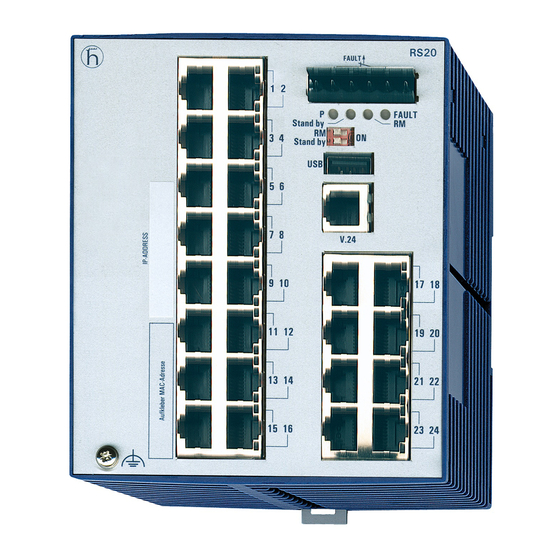
User Manual
Installation
Industrial Ethernet Rail Switch
RS20/RS30-...U Family (unmanaged)
+24V(P1)
3
4
P
LS
DA
5
6
LA learn
SW2
1
7
8
9
10
11
12
LS
DA
13
14
2
15
16
17
18
RS20
FAULT
+24V(P1)
0V 0V
+24V(P2)
LS
DA
P
FAULT
LA learn
ON
1
SW2
LS
DA
1
3
4
LS
DA
5
6
1
7
8
RS20/RS30...U
Release 01 06/2012
RS20
FAULT
0V 0V
+24V(P2)
LS
DA
FAULT
1
ON
LS
DA
1
LS
DA
1
19
20
LS
DA
21
22
1
23
24
+24V(P1)
3
4
LS
1
5
6
LA learn
DA
7
8
9
10
11
12
13
14
LS
2
15
16
DA
17
18
RS30
FAULT
+24V(P1)
0V 0V
+24V(P2)
P
FAULT
LA learn
ON
SW2
3
4
5
6
11
7
8
13
9
10
15
RS30
FAULT
0V 0V
+24V(P2)
P
FAULT
LS
DA
ON
SW2
1
19
20
21
22
LS
DA
23
24
2
25
26
12
14
16
RS30
FAULT
+24V(P1)
0V 0V
+24V(P2)
P
FAULT
LA learn
ON
SW2
3
4
5
6
7
8
9
10
Technical Support
https://hirschmann-support.belden.eu.com
Advertisement
Table of Contents


Need help?
Do you have a question about the RS30-...U Series and is the answer not in the manual?
Questions and answers